Virtual Evaluation of Static Structural Analysis of
Non- Manifold Assembly of Femur and Implant
Gabriel Oladeji Bolarinwa1, Sam Omenyi2 1
PhD Student, 2Professor, Mechanical Engineering Department, Nnamdi Azikiwe University, Awka, Anambra State, Nigeria
Abstract-Engineers apply classical mechanics (statics, dynamics, fluids, solids, thermodynamics, and continuum mechanics) to biological or medical problems. It includes the study of motion, material deformation, flow within the body and in devices, and transport of chemical constituents across biological and synthetic media and membranes. Progress in biomechanics has led to the development of the artificial heart and heart valves, artificial joint replacements, as well as a better understanding of the function of the heart and lung, blood vessels and capillaries, and bone, cartilage, inter-vertebral discs, ligaments and tendons of the musculoskeletal systems. The motivation is in being able to carry out this project to contribute into the orthopedic sector in the areas of pre-surgery, failure analysis, design of prosthesis and hips replacement with the use of finite element modeling. The problem with hip replacement technology is a challenging one and no addition to that effort is a wasted venture. The aim of this work is to carry out virtual Static Structural Analysis on Non Manifold Assembly of Femur and Implant at different body weights using MIMICS and ANSYS softwares for the analysis. Stainless Steel SS316L was used for the implant because of its biocompatibility and strength as stated in literatures. The weights were converted to pressures and were applied on the ball part of the prosthesis. The result obtained showed that the assembly has a good initial stability.
Keyword: Femur, Non-Manifold, Initial Stability, Implant, Static Structural Analysis.
I. INTRODUCTION
Complications do occur after surgical operation of implants because patient’s bones are of different properties depending on the state of the bone and the cause of the failure. The chance of dislocation increases after first dislocation, if revised. Recurrent dislocations are observed to be at higher occurrence rate than primary dislocations. The dislocation rate of 5.5% in revision surgeries stayed 3.8% higher than that of 1.8% in primary Total Hips Replacements (THRs). Besides, increasing probability of dislocation, it gives acute pain and abductor muscle damage distressing the confidence of patient as well as surgeon. Occurrence of dislocation lengthens hospital stay for patient and often requires revision surgery. Therefore, there is a need to address the above stated issues [16].The motivation is in being able to carry out this project to contribute into the orthopedic sector in the areas of pre-surgery, failure analysis, design of prosthesis and hips replacement with the use of finite element modeling. The problem with hip replacement technology is a challenging one and no addition to that effort is a wasted venture.
A. Aim and Objectives of this Study
The aim of this work considering stainless steel SS316L as the implant materials is to carry out Static Structural Analysis on Non Manifold Assembly of Femur-Implant .The objectives of this work are to:
1) Collect raw data that represent the desired anatomy of the bone, (CT scan or MRI of natural femoral joint).
2) Generate the solid model of the femur using Mimics software, 3-matics and others.
3) Model a standard stem to be used as implant using Creo Element Software.
4) Perform Virtual Pre-Surgical operation using the modeled implant as the prosthesis in the solid model of the femur generated from MIMICS to represent the artificial joint.
5) Assign a more realistic femoral material for finite element simulation.
6) Perform Static Structural Analysis using ANSYS Software and analyze of the results.
II. STRUCTURAL ANALYSIS
Technology (IJRASET)
ACQUISITION OF MEDICAL IMAGES
SEGMENTATION AND 3D RECONSTRUCTION OF FEMUR
BONE (MIMICS)
FE MESH GENERATION (SURFACE AND VOLUME) AND MATERIALS
ASSIGNMENT ON FEMUR (MIMICS)
SOLID MODELLING OF IMPLANT (CREO PARAMETRICS)
OSTEOTOMY OF FEMUR BONE AND PRE CLINICAL OPERATION
OFBONE-IMPLANT (MIMICS)
FE MESH GENERATION (SURFACE AND VOLUME) AND MATERIALS ASSIGNMENT ON
BONE-IMPLANT (MIMICS)
EXPORTATION OF THE BONE-IMPLANT TO ANSYS
(LOADS AND BOUNDARY CONDITIONS
POST PROCESSING AND RESULTS
ship hulls, aircraft bodies, and machine housings, as well as mechanical components such as pistons, machine parts, and tools.
III. METHODOLOGY
A. Finite Element (FE) Development
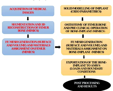
Finite Element Analysis of femur under physiologic conditions is essential for the understanding of failure mechanisms and providing guidance for the design and operation of femur replacement. Three dimensional FE models were created using CT images in Materialize Interactive Medical Image Control System (MIMICS) and various steps involved are described in Fig.1
B. Acquisition of Medical Images
Computed tomography (CT) uses x-rays to take pictures of sections of the body. A CT scan shows the body’s organs more clearly and in greater detail than regular x-rays. It helps find abnormalities in the body which may indicate disease, determine how far a disease has spread and show the effects of treatment and how your body is responding to it. CT scan images of 70 years old patient from abdomen downwards were acquired. The CT scans acquired were then imported into MIMICS software for segmentation and conversion to a format compatible with FE analytical software.
[image:3.612.131.505.394.697.2]1) Segmentation: The key to converting anatomical data from images to 3D models is a process called segmentation. During segmentation, the area of interest (the femur) was concentrated upon. Accurate segmentation is important in order to extract meaningful information from images. The medical images coming from CT or MRI scanners consist of grayscale information. MIMICS software was used to create models based on the grayvalues (Hounsfield units in CT images) within these images. A grayvalue is a number associated with an image pixel defining the shade (white, gray, or black) of the pixel (see figure 2) .There is a direct association between material density of the scanned object and the grayvalue assigned to each pixel in the image data. By grouping together similar grayvalues, the image data can be segmented, and models created. This type of segmentation is called thresholding and yields accurate models. The initial segmentation was then optimized in a 3D preview (Figure 3). After segmentation, the floating pixels were removed and it was the transformed into three dimension (3D). This makes editing very easy, since it allows true editing in 3D, which is easier to comprehend than 2D editing.
Figure 2: Femoral head masks
[image:4.612.130.503.110.669.2]Technology (IJRASET)
[image:5.612.72.540.151.366.2]Figure 3 was further cropped to the region of interest (femur) and further operations were carried out on the cropped part to acquire the desired solid model as shown in figure 4(a-c).
Figure 4: Transformation stages of CT scan to the refined femur model
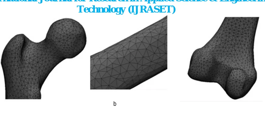
C. FE Mesh Generation
The bone was meshed in MIMICS environment and the materials were assigned and SOLID 185 Linear tetrahedron element based was adopted.
SOLID185 is used for 3-D modeling of solid structures. It is defined by eight nodes having three degrees of freedom at each node: translations in the nodal x, y, and z directions. The element has plasticity, hyperelasticity, stress stiffening, creep, large deflection, and large strain capabilities. It also has mixed formulation capability for simulating deformations of nearly incompressible elastoplastic materials, and fully incompressible hyperelastic materials.
SOLID185 Structural Solid is suitable for modeling general 3-D solid structures. It allows for prism, tetrahedral, and pyramid degenerations when used in irregular regions. Various element technologies such as B-bar, uniformly reduced integration, and enhanced strains are supported.
The total number of nodes in the model is 5441, total number of elements is 18532 and the total body elements is 18532. The meshing protocol that was used on the Femur model and the meshes were generated automatically, as follows: Reduce the amount of detail (Smoothing: Perform a Laplacian (1st order) )
Reduce the amount of triangles in the model Improve the quality of the triangles in the model
Reduce the amount of triangles while preserving the quality Remove extra shells.
Figure 5: A simple flow chart representing how the mesh works [10]
Technology (IJRASET)
Figure 6 (a&b): Surface Meshing of the femur model
Figures 6(a) shows irregular arrangement and quality of triangles after being transformed into CAD model. Following the remeshingprotocol highlighted above, the quality of the mesh was further refined to enhance the accuracy of the FEA results. Figure 6(b) shows the refined mesh, uniform triangles and perfect node arrangement.
IV. IMPLANT
An implant is an object made from non-living material that is deliberately inserted by a surgeon into the human body where it is intended to remain for a significant period of time in order to perform a specific function. Despite great number of metals and alloys known to man, remarkably few warrant preliminary consideration for use as implant materials. The relatively corrosive environment combined with the poor tolerance of the body to even minute concentrations of most metallic corrosion products eliminates from discussion most metallic materials [12].
A. Implant Materials
The possible metallic candidates, tantalum and the noble metals do not have suitable mechanical properties for the construction of most orthopedic tools and implants, while zirconium is in general too expensive today, titanium, cobalt chrome, zirconium and stainless steel 316 are the most frequently used biomaterials for internal fixation devices because of a favorable combination of mechanical properties corrosion resistance and cost effectiveness when Compared to other metallic implant materials. The biocompatibility of implant quality stainless steel has been proven by successful human implantation for decades.[13] Composition, microstructure and tensile properties of titanium, cobalt chrome, zirconium and stainless steel 316 used for internal fixation is standardized in International Standard (IS) and ASTM material specifications. Stainless steels also have superior mechanical properties and better corrosion resistance. The Ni-free compositions appear to possess an extraordinary combination of attributes for potential implant applications in the future [14].
B. Computer Aided Modeling of Implant and Preclinical Surgery
Figure7 shows an implant modeled with Creo Parametric software using the dimension of a standard implant. Implants are of different types and the factors that determine the selection are based on medical diagnosis. In this work, a long stem was be used.
[image:7.612.99.535.52.242.2]Figure 7: Modeled Implant from Creo Parametric software
C. Creation of Non-manifold assembly
[image:8.612.156.435.467.641.2]A non-manifold assembly is an object with more than one part, like the implant placed inside a cut femur bone in this case. When creating such an object, it is desired that the common surface is identical for both the parts. For this purpose, the Create non-manifold assembly operation was used. This operation will combine both meshes into one mesh, and maintain node continuity at the interface. The first process was to carry out Osteotomy on the femur bone. This is the process where the diseased femoral head is cut off and the implant is fixed. Femoral head angle is different for different individuals; there is a need to ascertain this angle before Osteotomy to prevent misalignment. This was achieved by exporting the femur model .After Osteotomy, the implant was fixed (see Figure 8 and 9).
The FE Model of the manifold comprises 6436 nodes and 12884 elements.
Technology (IJRASET)
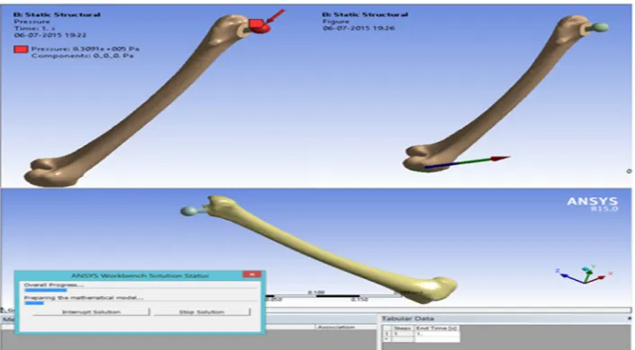
[image:9.612.179.411.312.456.2]Figure 9: Preclinical Operations and Non-Manifold Assembly
Figure 10: Volume Mesh of the Manifold Assembly representing the Artificial Joint
[image:9.612.169.437.507.642.2]V. SIMULATION AND ANALYSIS
A. Boundary Condition
The material of the bone is anisotropic and not homogeneous, in the modeling. The bone is made by two kinds of materials, compact and spongy, like a composite material. Therefore, for a realistic result, the bone was considered to be orthotropic.
For static analysis, these arbitrary loads 60kg, 70kg, 80kg, 90kg and 100kg were assumed. These are assumed to be the resultant loads acting on the femoral head of the patients while standing on one leg. These assumed loads will be converted into pressures and will be applied on the selected area of on the implant head. The constraint was placed at the distal end of the femur.
[image:10.612.62.535.224.344.2]VI. RESULTS
Table 1. Forces applied and their corresponding pressures on the areas of interest for bone-implant model S/N Assumed Patient Body Weight, W (kg) Corresponding Pressure (W/ Ai) (Pa) for
Bone-Implant
1 60 498545.90
2 70 581636.89
3 80 664727.88
4 90 747818.86
5 100 830909.84
6 120 997091.82
Ai (area highlighted with red colours) is the approximate area of the ball part of the implant as shown in figures 12 below. The area
was found to be 1.2035E-3 m2 respectively. These areas were used alongside with the assumed weights to calculate the pressures as shown in table 2.
[image:10.612.116.469.413.608.2]Technology (IJRASET)
For 60kg Force
13 (a) 13 (b) 13 (c)
For 70kg Force
13 (d) 13 (e) 13 (f)
For 80kg Force
For 90kg Force
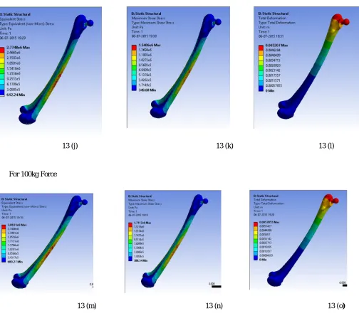
13 (j) 13 (k) 13 (l)
For 100kg Force
13 (m) 13 (n) 13 (o)
Figure 13(a-o): FE results obtained from Static Structural Analysis using ANSYS 15.0
[image:12.612.28.532.102.556.2]Technology (IJRASET)
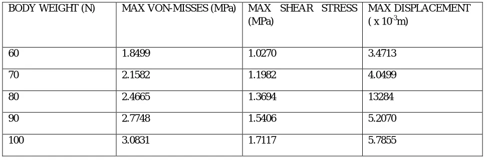
Table 2: Static analysis result obtained for Bone-Implant Model
VII. DISCUSSION
Rapid custom modeling of hard tissues (bones) using advanced computed tomography (CT) techniques is believed to be the most effective way of selection of the right implant design for surgery. Advanced computer aided engineering (CAE) techniques and FEA can also provide better examination and analysis of the designed implant before surgery operation to ensure high durability of the designed implant likewise the stability of the prosthetic joint.
After the analysis, it was observed from figures 13 (a-o) that the deformation increases with applied pressure. The von-mises stress, the shear stress and the deformation began to increase drastically from load 80kg through 100kg force. The pressures in table 1 were used in Finite element analysis using ANSYS 15.0 and the results obtained for the maximum values for Von-mises stress, shear stress and deformation are as shown in table 2. The stainless steel responded linearly to the pressure load applied that is, increase in load yields increase in deformation in a linear manner. Furthermore, compared to other metallic implant materials, the biocompatibility of implant quality stainless steel has been proven by successful human implantation for decades. Composition, microstructure and tensile properties of titanium, cobalt chrome, zirconium and stainless steel 316 used for internal fixation is standardized in International Standard (IS) and ASTM material specifications. Metallurgical requirements are stringent to ensure sufficient corrosion resistance, nonmagnetic response, and satisfactory mechanical properties. Torsional properties of stainless steel are different from titanium. Stainless steels are easier to handle because the surgeon can feel the onset of plastic deformation and this provides adequate pre-warning to avoid over-torque. SS316L is nickel-free and it was developed primarily to address the issue of nickel sensitivity. These stainless steels also have superior mechanical properties and better corrosion resistance. The Ni-free compositions appear to possess an extraordinary combination of attributes for potential implant applications in the future.. The results acquired from this study looks very realistic.
From the literatures, the ultimate tensile stress for SS316L to be 490MPa and 135-205 MPa for bone; the compressive strength of SS316L to be 570MPa and 70-80 Mpa for bone. From the analysis results, the maximum von-mises stress values obtained is 3.0831MPa for Bone-implant. The maximum stress values are far less than the compressive strength of the SS316L. Therefore, one can say that SS316L is a suitable material for the implant and the prosthetic joint (Non manifold assembly) considered in this work is safe under the assumed body weights.
REFERENCES
[1] Daniel J. Schneck, Joseph D.Bronzino: Biomechanics Principles and Applications pp 41-44.
[2] Eberhardt, A.W., Lewis, J.L., Keer, L.M., (1991). Contact of layered elastic spheres as a model of joint contact: effect of tangential load and friction. J. BiomechEng, 113, (107-108), ISSN 0148-0731.
[3] Lipshitz, H., Glimcher, M.J, (1979), In-vitro studies of the wear of articular cartilage. II Characteristics of the wear of articular cartilage when worn against stainless steel plates having characteristic surfaces. Wear, 52, (297-339), ISSN 0043-1648.
[4] McCutchen, C.W., (1962). The frictional properties of animal joints. Wear, 5, (1-17), ISSN 0043-1648.
[5] Brinckmann, P, Frobin, W., Hierholzer, E., (1981). Stress on the articular surface of the hip joint in healthy adults and persons with idiopathic osteo-arthrosis of the hip joint. J Biomech, 14, (149-156), ISSN 0044-3220
[6] G. Bergmann, G. Deuretzbacherb, et al. Hip contact forces and gait patterns from routine activities. Journal of Biomechanics, 34: 860, 2001.
[7] Amornsamankul, S.; Kaorapapong, K.et al ; Three-Dimensional Simulation of Femur Bone and Implant in Femoral Canal using Finite Element Method, International Journal of Mathematics and Computers in Simulation, volume 4, pp 171-178.
[8] A.E Yousif, M.Y Aziz, Biomechanical analysis of human femur during normal working and standing up IOSR Journal of Engineering, Volume 2, Issue 8 ,
BODY WEIGHT (N) MAX VON-MISSES (MPa) MAX SHEAR STRESS
(MPa)
MAX DISPLACEMENT ( x 10-3m)
60 1.8499 1.0270 3.4713
70 2.1582 1.1982 4.0499
80 2.4665 1.3694 13284
90 2.7748 1.5406 5.2070
Journal of Medical Engineering and Physics volume 30 (2008) pp 924–930.
[10] Mary Pham, Mesh Generation and its application to Finite Element Methods, Scientific and Industrial Computations (MOSAIC) August 24, 2009, pp 9. [11] VaclavBaca ,ZdenekHorak ,PetrMikulenka et al , Comparison of an inhomogeneous orthotropic and isotropic material models used for FE analyses. Elsevier
Journal of Medical Engineering and Physics volume 30 (2008) pp 924–930.
[12] Yegireddi Shireesha1, Dr S. V. Ramana, P.GovindaRao, Modelling and static analysis of femur bone by using different implant materials, IOSR Journal of Mechanical and Civil Engineering (IOSR-JMCE) e-ISSN: 2278-1684,p-ISSN: 2320-334X, Volume 7, Issue 4 (Jul. - Aug. 2013), PP 82-91
www.iosrjournals.org.
[13] Anna Nikodem, Correlations between structural and mechanical properties of human Trabercular femur bone, Acta of Bioengineering and Biomechanics,Vol. 14, No. 2, 2012.
[14] Matja` Godec, Material failure of an AISI 316l stainless steel hip prosthesis.
[15] Silke Renner, Determination of muscle forces acting on the femur and stress analysis, Chair of Structural Analysis, Technische Universität München, 2007, pp 77 .


![Figure 5: A simple flow chart representing how the mesh works [10]](https://thumb-us.123doks.com/thumbv2/123dok_us/8583058.861513/6.612.105.484.360.686/figure-simple-flow-chart-representing-mesh-works.webp)