ISSN: 1992-8645 www.jatit.org E-ISSN: 1817-3195
IDENTIFY AND CLASSIFY VIBRATION FAULT BASED ON
ARTIFICIAL INTELLIGENCE TECHNIQUES
1,2
MONEER ALI LILO *, 1L.A.LATIFF, 3AMINUDIN BIN HAJI ABU,
1
Razak School of Engineering and Advanced Technology, Universiti Teknologi Malaysia, Kuala Lumpur
Malaysia.
2
College of Science, department of physics, Al Muthana University, Iraq.
3
Malaysia - Japan International Institute of Technology, Universiti Teknologi Malaysia. Kuala Lumpur,
Malaysia.
E-mail: [email protected]
ABSTRACT
Steam turbines (ST) need to be protected from damaging faults in the event it ends up in a danger zone. Some examples of faults include vibration, thrust, and eccentricity. Vibration fault represents one of the challenges to designers, as it could cause massive damages and its fault signal is rather complex. Researches in the field intend to prevent or diagnose vibration faults early in order to reduce the cost of maintenance and improve the reliability of machine production. This work aims to diagnose and classify vibration faults by utilized many schemes of Artificial Intelligence (AI) technique and signal processing, such as Fuzzy logic-Sugeno FIS (FLS), Back Propagation Neural Network (BPNN) hybrid with FL-Sugeno (NFS), and BPNN hybrid with FL-Mamdani FIS (NFM). The signal of the fault and the design of the FL and NN were done using MATLB. The results will be compared based on its ability to feed the output signal to the control system without disturbing system behavior. The results showed that the NFS scheme is able to generate linear and stable signals that could be fed to modify the main demand of the ST protection system. This work concluded that the hybrid of more than one AI technique will improve the reliability of protection system and generate smooth signals that are proportional to the fault level, which can then be used to control the speed and generated power in order to prevent the increase of vibration faults.
Keywords: Artificial Intelligent Technique, Signals Processing, Fuzzy Logic, Neural Network, Fault
Identification.
1. INTRODUCTION
Vibration fault is a phenomenon that is mostly generated by rotating machines such as the induction motor, turbine, generator, and building. This fault will result in machine damage if it occurs frequently [1]. Turbine represents the core of a power plant. Vibration fault is generated on turbines due to factors such as elasticity, flexibility, and applied force [2]. Vibration fault signals
display non-linear characteristics [3].
A vibration fault signal in the time domain is unsuitable for analysis, monitoring, and diagnosing faults, thus, the signal needs to be transferred to the frequency domain by FFT [4]. Once in the frequency domain, it can be analyzed in computer applications, such as fuzzy logic (FL) and NN [5]. The NN can identify faults by learning NN with the health case. FL is a generation signal that is a
reflection of multi-input signals, which is representative of physical behaviors of system[6] [7]. The FL is made up of two types of FIS called the Sugeno and Mamdani FIS [8][9]. These techniques are related to AI, and can be used to identify, classify, and control the industrial environment for making decision [10]. researchers began to employ hybrid techniques for enhanced fault observation precision and augmenting the reliability of the controlling systems [11]–[13].
ISSN: 1992-8645 www.jatit.org E-ISSN: 1817-3195 began experimenting with hybrids of two intelligent
techniques, which leads to enhanced decision precision to detect faults. (Nguyen et al, 2015) proposed a new algorithm that can change the Membership Function (MF) setting value of the FL based on the error result from the training (ANFIS) ) [16]. (M. lilo et al, 2016) developed new algorithm to describe the number of the bearing and the level of the vibration fault on gas turbine by designed multi-stage of the NN[17]. (Panda & Patro, 2013) designed a new controller system that is related to the temperature of dry gas. However, work increases the efficiency operations for boilers. Eventually, the investigators installed a new controller system in the power plant [18].
On the other hand, AI utilized for fault detection based on hybrid tow technique enhances the decision precision and augmented the flexibility for fault identification and classification. (Rosa et al 2013) presented a hybrid neural with fuzzy model to predict and model fault signals in the time domain [19]. (Rang, 2012) utilized the fuzzy-neural technique to improve the system’s stability with robot application[20]. (Xie et al, 2010) developed a new scheme that is a combination of FL and NN. The new scheme is simpler than the conventional method in hardware implementation [21]. (Fei et al, 2014) designed a multi-stage of NN and other fault detection techniques that are used to diagnose the faults of the steam turbine. [22]. (McKee et al 2015) presented a procedure of detecting the vibration cavitation, which is based on the analysis vibration fault band and analysis statistical metrics. ISO 10816 is used with this work. to classify the fault [6]. Eventually, (Marichal g. et al, 2010) designed multi-stage AI technique to diagnose the Vibration faults on bearing, and the result showed that the FFT signal related to vibration fault improve the identification and classification[5]. (Huo-ching et al, 2013) was detected the vibration fault on steam turbine by utilized many algorithms, and compared between the neural and support vector classifier. The comparison was based on the training time and the algorithm accurate. The time of training of the radial basis function neural network (RBFNN), BPNN training by a steepest descent gradient algorithm (BPNN_GD), and
BPNN training by a Levenberg-Marquardt
algorithm (BPNN_LM) are 0.41s, 6.81s, and 0.72s, respectively [23].
This study goals to compare between three schemes were designed to identify and classify the
vibration fault on the steam turbine. The comparison was based on the linearity of the results to give the ability for effactting control signal with saving of system stablity. Morover, look for improvinge the precision of the identification and time training. The three schemes are related to utilize the Fuzzy logic and hybrid schemes which are contained fuzzy logic and neural network. The rest of this paper is structured as follows: Section 1 presents the basic information and related works. Section 2 explains the methodological design. Section 3 presents the design of signal processing, fuzzy logic, and the neural network. Meanwhile, Section 4 displays the hybrid schemes design. The analysis results of the three schemes are discussed in Section 5. Section 6 concludes this work.
2. METHODOLOGY DESIGN
ISSN: 1992-8645 www.jatit.org E-ISSN: 1817-3195
ISSN: 1992-8645 www.jatit.org E-ISSN: 1817-3195
3. STRUCTURE OF THE DESIGN
This section will discuss the generation of the vibration fault model, FLS design, and NN design where the error back propagation algorithm is used to implement NN.
3.1- Vibration fault signal model
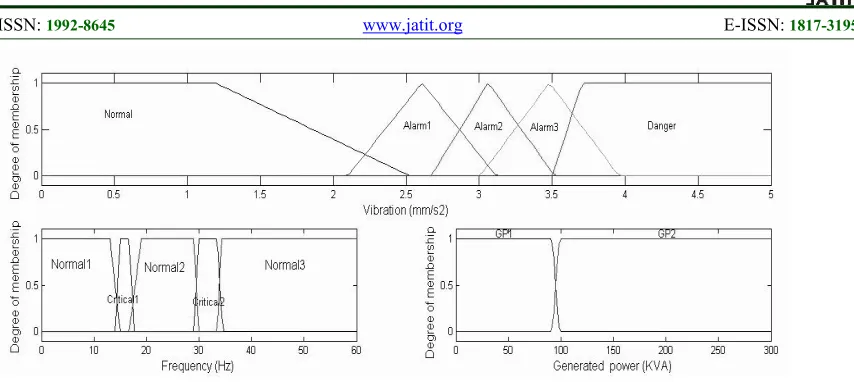
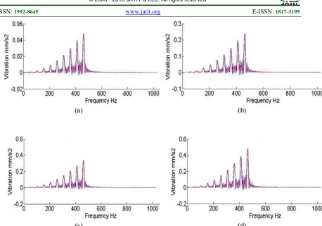
The vibration fault signal will be simulated as signals collected from the acceleration sensor. The signal will be in the time domain, while the corrupted error was added to the signal in order for it to be similar to the natural data, as shown in Figure 2(a). The vibration fault in time domain is unsuitable for the diagnosis or describing the situation of the fault, therefore, the signal will be transferred to the frequency domain by FFT after its noise is filtered. The resulted signal in the frequency domain is convenient to monitor the fault situation, but improper for controlling or protecting applications, as shown Figure 2(b). Thus, the proposed schemes will process, identify, and classify the fault signal using intelligent techniques to generate signal proportional to the fault level. The signal will be classified based on the ISO 18062-2, which is related to the description of the vibration fault of the ST, also, the frequency range of the signal is limited, depending on the speed of the turbine, where it is designed to travel between 0-50 Hz). The vibration fault signal is simulated based on the acceleration form, as shown in Equation 1.
A=v sin wt (Eq-1)
Where A is acceleration value in time
domain, v represents velocity amplitude in time
domain, ω=2πf, f is the machine frequency, t is the
time travel of the signal.
(a)
[image:4.612.312.517.77.290.2](b)
Figure 2: Vibration Fault Signal (a) Time Domain (b) Frequency Domain
3.2- Design Fuzzy System
FLS is utilized to enhance the control behavior or classification of the signal based on the inputs of the physical signals [24][25][26]. This technique can generate the linear signal represents the final decision which is reflected to the inputs signals. The inputs signals are collected from the industrial system or other applications to protect, control, or improve the system’s behavior based on the input datum. In this work, will use the Sugeno
FIS due to its output functionbeing able to generate
[image:4.612.95.306.530.674.2]ISSN: 1992-8645 www.jatit.org E-ISSN: 1817-3195
Figure 3: Sugeno input Member Ship function
3.3 Neural Network Design systems (Back propagation Algorithm)
NN is a technique utilized to distinguish between the healthy and faulty signal based on the heuristically analysis data which is saved during the learning the network. Generally, some kind of the NN algorithm need a teaching data called the supervisor type, while the second type is called the unsupervised NN, which does not need the learning data. In this work, the design of the NN was based on the Back Propagation Neural Network (BPNN) algorithm, which is one of the supervised NN algorithms. The fault signal generated in Section 3.1 will be used as the teaching to learn NN. The data was mapped for utilizing with NN applications, while the design of the NN in this work is mapped the input data separately, relying on a new technique that increases the identification precision of the NN. Also, the NN selects with 4 neurons for the input and output layers and 30 neurons for the hidden layer. The bipolar function was selected to calculate the final output value after multiplying the input data by the weights and adding it to the biases [28][10]. Thus, based on the mean square error of result which is produced from
ISSN: 1992-8645 www.jatit.org E-ISSN: 1817-3195
Figure 4: Different Level For Vibration Fault (a) First Level (b) Second Fault (c) Third Level (d) Fourth Lev El For Learning NN
Figure 5: MSE Values For (a) First Level (b) Second Level (c) Third Level (d) Fourth Level
4. IMPLEMENTATION OF NEURAL
-FUZZY SYSTEM
Recently, researchers have started
hybridizing techniques to create systems that can improve the precision of decisions for complex systems. This process will also enhance fault detection and system control [31][12][5][32]. This stage will involve the design of the NFS and NFM. NN was implemented and trained in Section 3.3 for utilization at this stage, while the FL parameters
design of the Sugeno and Mamdani FIS will be mention at this stage. The FLS was constructed based on three input MFs, the first will describe the vibration fault level, which sets based on the ISO 1806-2. The second classifies the frequency of the
machine (speed) into normal and critical
[image:6.612.97.528.425.562.2]ISSN: 1992-8645 www.jatit.org E-ISSN: 1817-3195 generated power conditions operation. Thus, the
output will be described the startup and generated power situations. The result will defuzzify the data using “wtaver”. These parameters and others that are used in the design of the FLS are shown in Table 1.
On the other hand, the Fuzzy logic-Mamdani (FLM) was designed with similar parameters of the FLS shown in table 1, but it only have two differences that are related to the type of output. The MFs in FLM scheme will be utilized instead of the constant function in FLS, due to the fundamental difference between FLS and FLM based on the method to create the output, where the defuzzification is utilized in the FLM, while the weight average is used with FLS.
[image:7.612.84.306.460.667.2]Finally, in this stage, two different algorithms will be designed. The first is the NFS, while the second is the NFM. These two models will be tested by applied on them similar fault signals to generate constant value that is proportional to the vibration fault. The comparison between these algorithms will be based on the stability and actuality to represent the vibration fault if it arises on the machine. Both schemes will apply the condition to put the neural network as functional part while, the FL will be in sleep mode until the occurrence of faults. This process will reduce the delay time process if applied on with experimental work.
Table 1 Fuzzy design parameters of Sugeno and Mamdani FIS
FIS Sugeno Mamdani
Number of rules 28 28
Number of input MFs 1 x 3 1x3
Vibration fault MF type trapmf trapmf
Frequency MF type trapmf trapmf
Generated power MF type
Zmf, smf Zmf, smf
Number of output MFs 1 x 2 1x2
Output during start up case
constant trapmf
Output during generated power case
constant trapmf
And method Prod Prod
Or method max Max
Implication Min Min
Defuzzifiction wtaver centroid
5. FAULT DIAGNOSIS RESULT BASED ON
MULTI-ALGORITHMS
The signals were generated in the section of the model the fault signal will be applied on three schemes to determine which scheme is better for identifying and classifying the vibration fault based on generated stable output that can be used with protection and control system. These three schemes are FLS, NFM, and NFS. Thus, the fault signal is applied into FL, which is designed with 3-input and 2-output, as mentioned in the previously Section 3.2. The result of fault identifying by the FLS showed that the scheme can classify the
vibration fault level and generated signal
ISSN: 1992-8645 www.jatit.org E-ISSN: 1817-3195
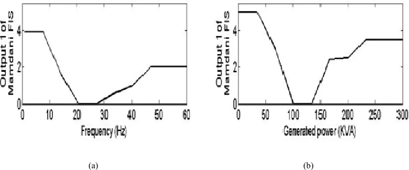
Figure 6: Showed Output of NSFS Related Different Situations at (a) Start up Case (b) Generating Power Case
The hybrid designs are related to mixing fuzzy with other techniques for the purpose of augmenting the precision of the protection system , depending on the environment of the applications [8][9][33]–[35]. The fault signal described in the modeling section was multiplied by four constant values to characterize the four situations of the vibration fault. These signals were used to train the NN in section of NN design. The results of NN training illustrated the successful learning based on the MSE result, as shown in Figure 5. Thus, the second scheme will consist of the NN and FLM, which will be utilized to discriminate and classify the fault during online cases based on the fault levels. The result proved that the fault was identified by the NN and classified by the FLM to
generate signals proportional to the fault level cases, as shown in Figure 7. The outputs of
the scheme were designed to take into account the effect of the speed and generated power, due to the fact that the vibration fault is affected by these values, as shown in Figure 7(a) and Figure 7(b), respectively. The result of this scheme is more linear compared to the results of the first scheme, but these data also needs to be processed to provide it with the ability to merge with control signals, which is the main goal of this work. The result showed when the fault situations were changed the output signal is transferred linearly to describe the new level of the fault, while in this work aspire to get sharp transaction of the fault situation, to improve the signal stability with time. Because the sharp transaction with time mean the precision of decision is enhanced. Thus, the disadvantage of this scheme is output not described the fault instantaneously if the input level was changed.
(a) (b)
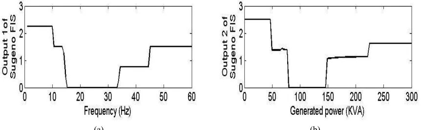
[image:8.612.99.520.515.690.2]ISSN: 1992-8645 www.jatit.org E-ISSN: 1817-3195 The last schemes that will be tested
contain the NN hybrid with FLS. The NFS scheme used the NN to identify the fault and FLS to classify the fault’s level while simultaneously confirm or dismiss the decision of the NN based on situation of the speed of the ST. The first state is related to the plotted output of the fault, taking into account the effect of the speed situation of the machine, as shown in Figure 8(a), while the second state describes the output, taking into account the generated power value, as shown in Figure 8(b). The schemes designed the output based on the speed and generated power value due to these parameters affecting the vibration fault levels [30].The result of this scheme showed that it is superior to the first and second scheme, as shown in Figure 8, where the NFM output describe the fault level with constant value to many training of same fault level, while the NFM gave linear signal arises to represented one level of the fault during multi-training. The result of the NFS is convenient for displaying the fault level while simultaneously utilizing to influence the main demand of the control system without disturbing the system’s
control stability. This process will protect the system from vibration fault if it occurs on the machine due to it described the level fault immediately if the fault is changed. Therefore this scheme has these advantages. firstly the NFS output is not needed to modify for influencing control signals or protection system, while the other schemes need more steps to processing the output to enhance the linearity of the result. Secondly, the training time of the neural network based on the back propagation error is less than time training of
the RBFNN, BPNN_GD, and BPNN_LM.
Therefore, the NFS is superior for identification, classification, and influencing the main demand to enhance the protection system’s properties. Eventually, all these schemes are needed training NN and reconstruct the membership functions of FL based on the machine parameters if applied on the others machine to diagnose the vibration fault only. While, the result will be changed if used with another fault type, which is represented weak points of these schemes.
[image:9.612.94.525.396.529.2](a) (b)
Figure 8: Showed Output of NFS Related to Four Different Situations during cases of (a) start up (b) Generating Power e
6. CONCLUSION
-The NFS and NFM scheme will confirm the decision twice; first by the NN, which declares the occurrence of vibration faults on the machine, followed by the NN waking up the FL to confirm or dismiss the decision based on the speed situations. If the FL confirmed the faults, it will lead to the classification of the fault level and generated signal that is proportional to the fault situation, which can be used to protect the machine from damages
- The result of the NFS scheme is superior to the NFM and FL, based on the smoothness
stability of the generated signal. NFS produce linear and stable data based on the duration time of the same fault level, which can be utilized to influence the main demand of the ST control system. This process will reduce faults based on the reduction of speed and generated power of the ST.
ISSN: 1992-8645 www.jatit.org E-ISSN: 1817-3195
REFERENCES:
[1] A. Broy and C. Sourkounis, “Torque control methods for active damping of vibrations in
drive systems of wind turbines,” 2014 Ninth
Int. Conf. Ecol. Veh. Renew. Energies, pp. 1– 7, Mar. 2014.
[2] K. H. Chan, E. J. Dozal-Mejorada, X. Cheng, R. Kephart, and B. E. Ydstie, “Predictive control with adaptive model maintenance:
Application to power plants,” Comput. Chem.
Eng., vol. 70, pp. 91–103, Nov. 2014.
[3] Z. Yanbing, L. Yibing, A. Hongwen, and Y. Keguo, “Fault recognition of large steam turbine based on higher order spectral features
of vibration signals,” 2011 IEEE Int. Conf.
Mechatronics Autom., pp. 1572–1577, Aug. 2011.
[4] H. Wentao, Y. Jun, Z. Xuezeng, and L. Xiaojun, “Fault Diagnosis for Steam Turbine Based on Flow Graphs and Naïve Bayesian Classifier,” pp. 396–401, 2014.
[5] G. Marichal, M. Artes, and J. Garcia-Prada, “An intelligent system for faulty-bearing
detection based on vibration spectra,” J. Vib.
Control, vol. 17, no. 6, pp. 931–942, Oct. 2010.
[6] K. K. McKee, G. L. Forbes, I. Mazhar, R. Entwistle, M. Hodkiewicz, and I. Howard, “A vibration cavitation sensitivity parameter based on spectral and statistical methods,”
Expert Syst. Appl., vol. 42, no. 1, pp. 67–78, Jan. 2015.
[7] I. McKee, K. K., Forbes, G., Mazhar, I., Entwistle, R., & Howard, “A review of major
centrifugal pump failure modes with
application to the water supply and sewerage
industries.,” ICOMS asset Manag. Conf. (p.
32). Gold Coast, QLD., 2011.
[8] C. A. Gama, A. G. Evsukoff, P. Weber, N. F. F. Ebecken, and S. Member, “Parameter Identification of Recurrent Fuzzy Systems
With Fuzzy Finite-State Automata
Representation,” vol. 16, no. 1, pp. 213–224, 2008.
[9] A. K. Pani and H. K. Mohanta, “Soft sensing of particle size in a grinding process: Application of support vector regression, fuzzy inference and adaptive neuro fuzzy inference techniques for online monitoring of
cement fineness,” Powder Technol., vol. 264,
pp. 484–497, Sep. 2014.
[10] M. KangaraniFarahani and S. Mehralian,
“Comparison between Artificial Neural
Network and neuro-fuzzy for gold price
prediction,” 2013 13th Iran. Conf. Fuzzy Syst.,
pp. 1–5, Aug. 2013.
[11] Z. M. Nopiah, A. K. Junoh, and A. K. Ariffin, “Vehicle interior noise and vibration level assessment through the data clustering and
hybrid classification model,” Appl. Acoust.,
vol. 87, pp. 9–22, Jan. 2015.
[12] H. Xiao, J. Zhou, J. Xiao, W. Fu, X. Xia, and W. Zhang, “Identification of vibration-speed curve for hydroelectric generator unit using statistical fuzzy vector chain code and support
vector machine,” Proc. Inst. Mech. Eng. Part
O J. Risk Reliab., vol. 228, no. 3, pp. 291– 300, Dec. 2013.
[13] P. S. Londhe, B. M. Patre, and A. P. Tiwari,
“Design of Single-Input Fuzzy Logic
Controller for Spatial Control of Advanced
Heavy Water Reactor,” Trans. Nucl. Scince
,IEEE, vol. 61, no. 2, pp. 901–911, 2014. [14] Y. Zhang, S. Huang, W. Gao, and T. Shen,
“Vibration Fault Diagnosis of Steam Turbine
Shafting Based on Probability Neural
Networks,” 2008 Congr. Image Signal
Process., pp. 582–585, 2008.
[15] M. A. Lilo, L. A. Latiff, A. Bin, H. Abu, and Y. I. Al Mashhadany, “VIBRATION FAULT
DETECTION AND CLASSIFACTION
BASED ON THE FFT AND FUZZY
LOGIC,” ARPN J. Eng. Appl. Sci., vol. 11, no.
7, pp. 4633–4637, 2016.
[16] S. D. Nguyen, Q. H. Nguyen, and S.-B. Choi, “Hybrid clustering based fuzzy structure for vibration control – Part 1: A novel algorithm
for building neuro-fuzzy system,” Mech. Syst.
Signal Process., vol. 50–51, pp. 510–525, Jan. 2015.
[17] M. A. Lilo, L. A. Latiff, A. Bin Haji Abu, Y. I. Al Mashhadany, and A. K. Ilijan, “Gas Turbine Bearing and Vibration Classification
of Using Multi-layer Neural Network,” IEEE
Conf. ICSSA2015, pp. 3–6, 2015.
[18] S. Panda and A. K. Patro, “ADAPTIVE
NEURO-FUZZY CONTROLLER FOR
THERMAL POWER PLANT CONTROL METHOD OF,” vol. 2, no. 6, pp. 99–102, 2013.
[19] R. Rosa, F. Gomide, and R. Ballini, “Evolving Hybrid Neural Fuzzy Network for System
Modeling and Time Series Forecasting,” 2013
ISSN: 1992-8645 www.jatit.org E-ISSN: 1817-3195 [20] H.-J. Rong, “Indirect Adaptive Fuzzy-Neural
Control of Robot Manipulator,” 2012 IEEE
14th Int. Conf. High Perform. Comput. Commun. 2012 IEEE 9th Int. Conf. Embed. Softw. Syst., pp. 1776–1781, Jun. 2012. [21] T. Xie, H. Yu, and B. Wilamowski,
“Replacing fuzzy systems with neural
networks,” 3rd Int. Conf. Hum. Syst. Interact.,
vol. 2, no. 1, pp. 189–193, May 2010.
[22] X. Fei1, Z. Hao, and P. Daogang, “Fault Diagnosis in Power Plant Based on
Multi-Neural Network,” IEEE Int. Conf. Syst. Sci.
ang Eng., 2014.
[23] H.-C. Sun, C.-M. Huang, and Y.-C. Huang, “Fault Diagnosis of Steam Turbine-Generator Sets Using an EPSO-Based Support Vector
Classifier,” IEEE Trans. Energy Convers.,
vol. 28, no. 1, pp. 164–171, Mar. 2013. [24] C. V. Isaza, H. O. Sarmiento, T.
Kempowsky-Hamon, and M.-V. LeLann, “Situation prediction based on fuzzy clustering for
industrial complex processes,” Inf. Sci. (Ny).,
vol. 279, no. 7, pp. 785–804, Sep. 2014. [25] W. Yue, Y. Cai, Q. Rong, C. Li, and L. Ren,
“A hybrid life-cycle and fuzzy-set-pair
analyses approach for comprehensively
evaluating impacts of industrial wastewater
under uncertainty,” J. Clean. Prod., vol. 80,
pp. 57–68, Oct. 2014.
[26] B. Wen and H. Li, “A PLMF-Based Decomposition–Coordination Algorithm for Fuzzy Linear Programming in Industrial
Applications,” Arab. J. Sci. Eng., vol. 39, no.
10, pp. 7467–7474, Aug. 2014.
[27] K. K. McKee, G. L. Forbes, I. Mazhar, R. Entwistle, I. Howard, and T. Mapeza, “Modification of the ISO-10816 centrifugal pump vibration severity charts for use with Octave band spectral measurements,” in
Advances in Applied Mechanics Research, Conference Proceedings - 7th Australasian Congress on Applied Mechanics, ACAM 2012, 2012, pp. 276–283.
[28] JACEK M. ZURADA, Introduction to
Artificial Neural System. New York -United States of America: west publishing company, 1992.
[29] M. Elhefnawi and M. Mysara, RECURRENT
NEURAL NETWORKS ANDSOFT
COMPUTING. Croatia: Janeza Trdine 9, 51000 Rijeka, Croatia, 2012.
[30] M. Lilo, L.A.Latiff, A. Abu, and Y. Al
Mashhadany, “WIRELESS FAULT
TOLERANCES DECISION USING
ARTIFICIAL INTELLIGENCE
TECHNIQUE,” J. Theor. Appl. Inf. Technol.,
vol. 87, no. 2, pp. 324–335, 2016.
[31] A. S. Raj and N. Murali, “Early Classification of Bearing Faults Using Morphological
Operators and Fuzzy Inference,” IEEE Trans.
Ind. Electron., vol. 60, no. 2, pp. 567–574, Feb. 2013.
[32] V. Muralidharan and V. Sugumaran, “Rough set based rule learning and fuzzy classification of wavelet features for fault diagnosis of
monoblock centrifugal pump,” Measurement,
vol. 46, no. 9, pp. 3057–3063, Nov. 2013.
[33] C.-W. Chen, “Applications of linear
differential inclusion-based criterion to a
nonlinear chaotic system: a critical review,” J.
Vib. Control, vol. 18, no. 12, pp. 1886–1899, Dec. 2011.
[34] H. Du, J. Lam, K. C. Cheung, W. Li, and N.
Zhang, “Direct voltage control of
magnetorheological damper for vehicle
suspensions,” IOP Sci. Smart Mater. Struct.,
vol. 22, no. 10, p. 105016, Oct. 2013.
[35] A. Boukabou and N. Mansouri, “T-S fuzzy
control of uncertain chaotic vibration,” Shock
Vib., vol. 19, pp. 379–389, 2012.