Multiband Shared Aperture Adaptive Array
Using the Rear Defogger
Yoshihiko Kuwahara
Graduate School of Science and Engineering Shizuoka University
Hamamatsu, Japan [email protected]
Noorsaliza Abdullah
Department of Communication Engineering Universiti Tun Hussein Onn Malaysia
Batu Pahat, Johor, Malaysia [email protected]
Abstract— Conventional adaptive array consists of several antennas. However, for vehicular industrial design, it is preferable not to use additional antenna elements. Therefore, we propose a multiband shared aperture adaptive array antenna using a rear defogger. In addition, RSAA (reactive steered adaptive array) concept is applied for simplification and low power consumption. From simulation and experiments results, it shows that the proposed adaptive antenna can operate at 100 MHz (ISDB-TSB) and 210 MHz (ISDB-TMM) band and that it also
has the phase diversity capabilities in the Rayleigh fading environment.
Keywords-component; rear defogger, reactive steered adaptive array; phase diversity; symplex method
I. INTRODUCTION
A reactively steered adaptive array (RSAA) is known as an adaptive array with a single receiver and several radiating elements such as a dipole or patch [1]. Though the configuration is simple, the structure is bulky because of the use of mutual coupling between elements in the array antenna. This restricts its implementation. Also, it is impossible to form an adaptive pattern in mobile communication environments because of a large amount of calculation that results from the use of a blind algorithm. Moreover, the bandwidth has not been examined in detail.
We examine an adaptive array for the future digital radio, ISDB-Tsb (Integrated Services Digital Broadcasting -
Terrestrial for Sound Broadcasting : 90-108MHz), ISDB-Tmm
(Integrated Services Digital Broadcasting Terrestrial for mobile multimedia : 207.5-222MHz) [2], installed on a vehicle. Ordinary RSAA cannot be installed on a vehicle because of their large size. By the way, the use of a rear defogger for the FM and AM antenna has been examined [3]. We proposed using a defogger as the RSAA by placing several ports on it [4]. We used the simplex method to achieve robust beamforming with rapid convergence [5]. In addition, we confirmed that the proposed antenna was able to operate in multiband [6].
In this paper, we present the shared-aperture smart antenna using a defogger by numerical simulation and experiments. The proposed antenna can operate at 100 MHz and 210 MHz band. Also, it has the phase diversity capability in the Rayleigh fading environment, while it has the null steering capability.
II. ADAPTIVE ARRAY USING THE REAR DEFOGGER
A. Shared Aperture Based on a Rear Defogger
We use a 1:5 scale model for both the experiments and numerical simulation. Therefore, the frequency of ISDB-Tsb
and that of ISDB-Tmm for the scale model is set to 450540
MHz and 1037.5-1110MHz, respectively. We examine the model by installing it on a vehicle. Figure 1 shows the defogger aperture installed on a vehicle. To increase the coupling between ports (CBP) and to decrease the spatial cross-correlation (SCC) for each band, four vertical wires are added. We place four ports on the outer heating wire and operate it as an array antenna with four elements.
Mounting it on a metal body as shown in Fig. 1 (b), we evaluate the performance on the basis of the voltage standing
(a) Detail Dimensions of the Rear Defogger
wave ratio (VSWR), CBP, and SCC. For an array that operates in a mobile communication environment, VSWR and SCC should be low over the bandwidth [7], while CBP should be large for an RSAA. We evaluated the parameters VSWR, CBP, and SCC by using an IE3D electromagnetic simulator. We examined more than 100 possible port positions to decide the port positions.
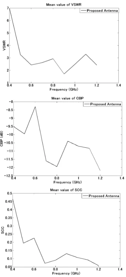
[image:2.595.307.558.55.209.2]Figure 2 shows frequency characteristics of VSWR, CBP, and SCC in case of the proposed antenna scheme. Here, the output port is port 1, and the others are connected with the short. For CBP and SCC, the curves are average of all combinations of the paired ports for. The VSWR is less than 4. the CBP is larger than -11dB, and the SCC is less than 0.25 over the specified bandwidths.
Figure 2 Frequency characteristics of VSWR, CBP, and SCC
B. Adaptive Beamforming
[image:2.595.61.268.215.668.2]Figure 3: Implementation of RSAA to a rear defogger.
Figure 4 Reception of the delayed signal
[image:2.595.319.555.240.387.2]III. SIMULATION
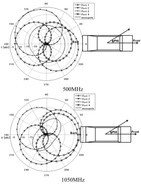
We calculate radiation patterns to confirm that they cover the whole horizontal plane. Figure 5 shows the horizontal patterns for 2 bands. Coverage over 360º in the horizontal plane is achieved by 4 patterns corresponding with 4 ports.
In the next, we evaluate improvement of SINR where the environment includes the interference. We assume two incoming waves; namely as desired signal and delayed signal (interference). Both signals have the same amplitude. The DOAs in horizontal plane is randomly determined in the range of 0°-360°, while DOAs in vertical plane is set to 0.48° based
500MHz
[image:3.595.35.282.190.511.2]1050MHz
Figure 5 Horizontal patterns of 4 ports
Figure 6 CDF of the SINR
on measurement field. We calculated complementary cumulative distribution function (CCDF) of SINR for 100 combinations of incident waves. From the statistical analysis, we can see that for two frequency bands more than 80% of the signals have SINR greater than 20 dB.
IV. EXPERIMENTS
A. Setup
We manufactured the proposed antenna on a 1:5 scale and installed it on a vehicular model(Fig.7). We then evaluated the antenna in the anechoic chamber. Table 1 shows the experiment conditions.The transmitting frequency is 473MHz and 900MHz, because of the experimental equipment especially the existed fading simulator. Figure 2 show that the proposed antenna has good performance at 900MHz.
[image:3.595.50.394.195.714.2]Figure 7 1/5 Scale Model
Table 1 Experiment Conditions
[image:3.595.321.545.364.699.2]Figure 9 BER characteristics
B. Operation in the Rayleigh Fading
The scale model is installed in the center of the fading simulater as shown in Fig.8. The bit error rate (BER) has been measured while the Doppler frequency, transmitting power, and the polarization is changed. Figure9 shows the results. BERs of the operating conditions are improved compared with those of no operation.
C. Adaptive Beamforming
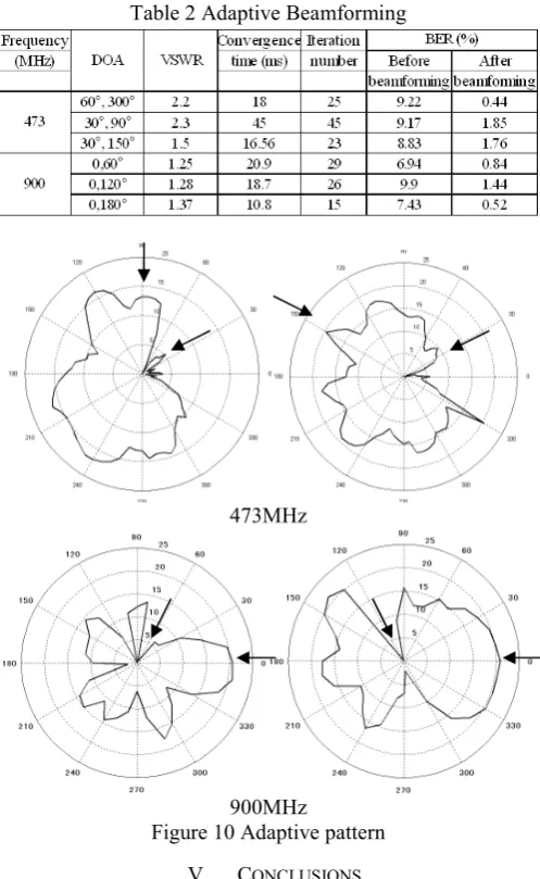
[image:4.595.309.558.241.646.2]2 signals with the same amplitude are incident from a variety of DOAs. Under the situation, adaptive beamforming is carried out. VSWR of output after the adaptive beamforming, convergent time, and BER were measured. The examples are shown in Table 2 and Figure10. Adaptive beam patterns are successfully formed in the dual band.
Table 2 Adaptive Beamforming
473MHz
900MHz
Figure 10 Adaptive pattern
V. CONCLUSIONS
MHz (ISDB-TMM) band and that it also has the diversity
capabilities in the Rayleigh fading environment.
References
[1] R. F. Harrington, “Reactively controlled directive arrays,” IEEE Trans. Antennas and Propagat., Vol. AP-26, No. 3, May 1978, pp. 390-395. [2] ARIB STD-B31.
[3] V. Ravinovich, N. Alexandrov, and B. Alkhateev, Automotive Antenna
Design and Application, CRC Press, 2010.
[4] N. Abdullah and Y. Kuwahara, “VHF Adaptive antenna Using the Rear Defogger” IEEE Trans. on Antennas and Propagation, Vol.60 No.3,2012 (in press).
[5] N. Abdullah, and Y. Kuwahara,Steerable antenna using algorithm based on downhill simplex method, Progress in Electromagnetics Research C, Vol.22, pp.23-34, 2011.
[6] N. Abdullah, and Y. Kuwahara, “ Multiband Shared Aperture Adaptive Array using the Rear Defogger,” Proceedings of ISAP2011, A06_1012. [7] T. Taga, “Analysis for mean effective gain of mobile antennas in land