Second Order Sliding Mode Controller for
Longitudinal Wheel Slip Control
Norhazimi Hamzah
Faculty of Electrical Engineering Universiti Teknologi MARA
Pulau Pinang, Malaysia [email protected]
Yahaya Md Sam, Hazlina Selamat
Faculty of Electrical Engineering Universiti Teknologi Malaysia
Johor, Malaysia
[email protected], [email protected]
M Khairi Aripin
Control, Instrumentation & Automation Department. Faculty of Electrical Engineering, UTeM
Melaka, Malaysia [email protected]
Rozaimi Ghazali
Faculty of Electrical and Electronic Engineering Universiti Tun Hussein Onn Malaysia
Johor, Malaysia [email protected]
Abstract— This paper investigates the longitudinal wheel slip tracking control approach for ground vehicle. A mathematical model of a quarter vehicle undergoing a straight-line braking maneuver is used as the control model. Second order sliding mode (SOSM) control approach using super-twisting technique is proposed to manipulate the braking torque to control the wheel slip. The effectiveness of the SOSM is compared to the conventional sliding mode in the simulations of emergency straight line braking in Simulink. With the SOSM, the chattering phenomenon is eliminated, giving a smooth tracking trajectory and lower slip error and control effort.
Keywords—Sliding Mode Control, Wheel slip, super-twisting
I. INTRODUCTION
Vehicle active control system such as antilock braking system (ABS), traction control system (TCS) and electronics stability program (ESP) have been developed and researches on them are still actively conducted in order to enhance the active driving safety feature of ground vehicle.
In the above mentioned active control system, tire longitudinal slip ratio or so called wheel slip has greatly influences the performance of braking, traction and stability control. The longitudinal slip ratio is defined as the difference between the vehicle speed and the wheel speed normalized by the vehicle speed (for braking).As this wheel slip ratio has significant role in affecting the quality of vehicle control, it has become an active research area in the automotive field. For ABS, the wheel slip ratio is control to prevent wheel lock up and to maintain the friction coefficient within maximum range to ensure minimum stopping distance [1, 2]. As for the ESP, the wheel slip ratio is controlled such that the resultant forces required to control the vehicle states can obtained [3]. Accordingly, by controlling the wheel slip
ratio of each tire to run at its corresponding desired slip value, the desired control objective can be obtained.
However, the wheel slip dynamics control is a challenging problem due to the highly nonlinear and complex structure of the tire. In addition, the system is also suffered with parametric uncertainties and subjected to external disturbance from the environment. Thus, it is required to design a robust control to overcome these ambiguities. Sliding mode control (SMC) is a well known robust control technique to overcome problems such as external disturbance, parameters uncertainties and unmodeled dynamics. The application of SMC in wheel slip control has been broadly addressed in the literatures [1-8].
Various techniques of the sliding mode controller were implemented in these previous researches. In [8], second order sliding mode (SOSM) is proposed for active braking system to control the wheel slip of two wheeled vehicle. Studies in [4] also proposed a second order sliding mode traction controller that designed for traction control by maintaining the wheel slip at desired value and road-tire adhesion coefficient is estimated using sliding mode based observer. With this control scheme, traction force control is enable to avoid skidding and spinning during braking and acceleration respectively. In [5], SMC is utilized to control the wheel slip where the driving/braking torque of each wheel is manipulated to track the desired wheel slip. Studies in [6] design a stable sliding surface based on linear matrix inequalities (LMI) while [7] integrate the SMC with integral switching surface to attenuate the chattering effects where the control performance is better as compared to fuzzy controller, neural network hybrid and self-learning fuzzy-sliding mode.
-20 -15 -10 -5 0 5 10 15 20 -4000
-3000 -2000 -1000 0 1000 2000 3000 4000
slip(%)
Fx
(N
) at
Fz
=
4
00
0N
mu=0.9 mu=0.7 mu=0.5 mu=0.3 mu=0.1 (SOSM) that has higher accuracy and able to generate
continuous control action is enhanced for wheel slip control. In this paper, super twisting based sliding mode control based is proposed to control the wheel slip of traction/braking control. Dynamic model for controller design is brief in Section II. Section III presented a robust control design using super-twisting second order sliding mode approach, results of the control performance is discussed in Section IV and conclusion is provided in Section V.
II. SYSTEM MODELING A. Vehicle and Wheel Dynamics
In this section, a simplified model of the quarter vehicle undergoing braking maneuver is developed. The controlled vehicle is assumed to be in straight line braking on a flat road surface. Thus, the lateral tire force and yaw do not exist. By applying Newton’s Law; the dynamic equation of vehicle motion for linear acceleration and the dynamic equation of the angular motion of the wheel are as follow
m F
V=− x (1)
w w x b
I
R
F
T
−
=
ω
(2)where V indicates the longitudinal speed of vehicle center of mass vehicle velocity, Fxthe tire longitudinal force, mthe total mass of quarter vehicle, ωthe angular speed of the wheel, Tbthe braking torque, Rwthe wheel
[image:2.595.313.516.303.518.2]radius, and Iwthe moment of inertia of the wheel.
Figure 1. The quarter car vehicle model.
B. Tire model
The tire longitudinal force ( Fx ) is a nonlinear function of the normal load, the road friction coefficient and the longitudinal slip and slip angle of the tire as described by the well known Magic Formula [9].
vx x x x
x
x D C B S
F = sin( tan−1( ϕ ))+ (3)
where
)) (
( tan )
)( 1
( 1 x hx
x x hx x
x B B S
E S
E + + +
−
= λ − λ
ϕ
The parameters B*,C*,D*andE*are obtained by fitting to experiment data for a specific tire and specific road condition. Sample plot of the longitudinal force versus the longitudinal slip and is shown in figure 2. Thus, this force can be controlled by varying the longitudinal slip by manipulating the wheel braking torque [3].
The longitudinal force produced by the wheel is bounded, i.e.,
Ψ ≤ x
F (4)
For the transient tire behavior, the traction force Fx has a bounded first time derivative
Γ ≤ x
[image:2.595.88.267.470.623.2]F (5)
Figure 2. The tire longitudinal force at tire pure braking/driving
C. Wheel longitudinal slip dynamics
The longitudinal slip during braking is given by:
V V Rw− = ω
λ (6)
Taking derivative of the longitudinal slip with respect to time is
V V
Rw
ω (1 λ)
λ= − + (7)
V V V V V I TbR V I R F w w w w x λ
λ= 2 − − − (8)
III. SLIPCONTROLLERDESIGN
In general, the design procedure of sliding mode control technique can be divided into two steps. The first step is to design the sliding surface such that the system response in the sliding mode has the desired properties. The second step is to design the control law to bring the trajectory of the system onto the surface for a sliding mode to be realized in finite time.
The controller design is based solely on the slip dynamics by disregarding the actuator dynamics [8]. The control objective is to drive the longitudinal slip to the desired slip in finite time. And in order to have the system track the desired slip(λd), the sliding variable is defined as the error between the desired slip and the actual slip
d
e λ λ
σ = = − (9)
Thus, if σ can be forced to zero, then the error can converged to zero so that the desired dynamic can be attained. The chosen sliding surface is defined as
0
=
σ (10)
The first derivatives of the sliding variable are
d w w b w w x d V V V V V I R T V I R F λ λ λ λ σ − − − − = − =
2 (11)
u
γ φ
σ= + (12)
where u,γand φare defined as
b
T
u= (13)
V I R w w =
γ (14)
d w w x V V V V V I R F λ λ
φ = 2 − − − (15)
From (1) and (4),
1 f m
V ≤Ψ = (16)
And from (2) and (4),
2 f I R T w w b − Ψ = ≤
ω (17)
Based on (16) and (17), the parameter φ is bounded. This means that when a constant braking torque Tbis applied, the derivative of the wheel slip ratio is bounded [4, 8].
The relative degree of the sliding variable to the control input is one, thus the control law is developed based on the super-twisting control algorithm to avoid chattering. Consider again (12),
) ( ) , ( ) , ( )
(t φ t x γ t xut
σ = +
where )φ(t,x and )γ(t,x are smooth uncertain functions with φ ≤Φ>0, 0<Γm≤γ ≤ΓM.
The super- twisting algorithm is converged to the 2-sliding set (σ =σ =0) in finite time [10]. The trajectories of the super- twisting are characterized by twisting around the origin of the phase portrait of the sliding variable. The control law u(t)is defined as a combination of two terms. The first term is defined as its discontinuous time derivative whereas the second term is the continuous function of the sliding variable which is present during the reaching phase only [11].
) ( ) ( )
(t u1 t u2 t
u = + (18)
⎪⎩ ⎪ ⎨ ⎧ ≤ − > −
= ( ) 11
) (
1 Wsign u
u u t u σ (19) ⎪⎩ ⎪ ⎨ ⎧ ≤ − > − = 0 0 0 2 ) ( ) ( ) ( σ σ σ σ β σ σ σ σ β ρ ρ sign sign t
u (20)
whereW , β and ρ are the design parameters. The
sufficient condition for finite time convergence to the sliding surface are
5 . 0 0 ) ( ) ( 4 2 2 ≤ < Φ − Γ Γ Φ + ΦΓ ≥ Γ Φ > ρ β W W W M m M m (21)
The choice of ρ=0.5assures that sliding order 2 is
achieved [11].
IV. RESULT AND DISCUSSION
Simulations are carried out in Matlab Simulink by assuming a straight line braking scenario, thus the steering angle input is zero. The simulations were performed on two types of sliding mode controller, first with conventional sliding mode controller (SMC) and second with second order sliding mode controller (SOSM) with super-twisting control algorithm.
in Figure 3-7. Both type of controller are able to track the desired slip trajectory precisely, which is the advantage of sliding mode controller. However, the result using conventional sliding mode controller shows some chattering in all the response. This phenomenon is highly undesirable as it may lead to damage on the physical actuator. In addition, the conventional sliding mode
controller (SMC) also illustrates higher control effort compare to the second order sliding mode (SOSM). With the SOSM, the chattering phenomenon is eliminated, giving a smooth tracking trajectory and lower slip error and control effort.
0 0.2 0.4 0.6 0.8 1 1.2 1.4 0
5 10 15 20 25
30 With SMC
t(sec)
sp
e
e
d
(m
/s
)
[image:4.595.320.523.188.340.2]Vehicle speed Wheel speed
Figure 3. The vehicle and wheel speed with conventional sliding mode controller
0 0.2 0.4 0.6 0.8 1 1.2 1.4 0
5 10 15 20 25 30
With SOSM
t(sec)
s
p
ee
d(
m/
s
)
[image:4.595.72.277.191.341.2]Vehicle speed Wheel speed
Figure 4. The vehicle and wheel speed with second order sliding mode controller
0.1 0.15 0.2 0.25 0.3 0.35 0.4 0.45 0.5
-0.4 -0.3 -0.2 -0.1 0
Longitudinal slip
t(sec)
s
lip
(%
)
Desired SOSM SMC
Figure 5. The longitudinal wheel slip chattering
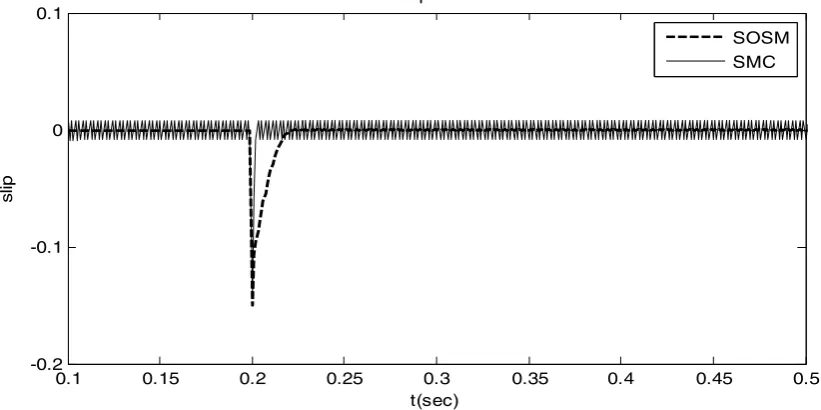
[image:4.595.95.503.452.669.2]0.1 0.15 0.2 0.25 0.3 0.35 0.4 0.45 0.5 -0.2
-0.1 0 0.1
slip error
t(sec)
slip
[image:5.595.95.506.80.285.2]SOSM SMC
Figure 6. The longitudinal wheel slip error
0 0.05 0.1 0.15 0.2 0.25 0.3 0.35 0.4 0.45 0.5
-1 -0.5 0 0.5 1 1.5
2x 10 4
t(sec)
Tb
(
N
m)
Braking torque
[image:5.595.91.509.81.595.2]SOSM SMC
Figure 7. The braking torque
CONCLUSION
A robust controller, based on sliding mode approach to control the wheel slip is presented in this paper. The strategy using super-twisting control algorithm able to eliminate the chattering problem, thus improving the performance of the wheel slip control.
ACKNOWLEDGMENT
REFERENCES
[1] H. Daegun, H. Inyong, Y. Paljoo, and K. Huh, "Development of a vehicle stability control system using brake-by-wire actuators," Journal of Dynamic Systems, Measurement and Control, Transactions of the ASME, vol. 130, pp. 0110081-0110089, 2008. [2] N. Hamzah, Y. M. Sam, and A. A. Basari, "Enhancement of
Driving Safety Feature via Sliding Mode Control Approach," in Fourth International Conference on Computational Intelligence, Robotics and Autonomous Systems Palmerston North, New Zealand, 2007, pp. 116-120.
[3] J. Wang and R. G. Longoria, "Coordinated and reconfigurable vehicle dynamics control," IEEE Transactions on Control Systems Technology, vol. 17, pp. 723-732, 2009.
[4] M. Amodeo, A. Ferrara, R. Terzaghi, and C. Vecchio, "Wheel slip control via second-order sliding-mode generation," IEEE Transactions on Intelligent Transportation Systems, vol. 11, pp. 122-131, 2010.
[5] N. Hamzah, Sam, Y.M. and Shuib, N.M., "Longitudinal Tire Slip Control Utilizing Sliding Mode Control," in The Second International Conference on Control, Instrumentation and Mechatronic Engineering (CIM09), Malacca, Malaysia, 2009, pp. 62-65.
[6] Y. E. Mao, Y. Zheng, Y. Jing, G. M. Dimirovski, and S. Zang, "An LMI approach to slip ratio control of vehicle antilock braking systems," in Proceedings of the American Control Conference, 2009, pp. 3350-3354.
[7] A. Harifi, A. Aghagolzadeh, G. Alizadeh, and M. Sadeghi, "Designing a sliding mode controller for slip control of antilock brake systems," Transportation Research Part C: Emerging Technologies, vol. 16, pp. 731-741, 2008.
[8] M. Tanelli and A. Ferrara, "Active braking control for two-wheeled vehicles via switched second order sliding modes," in Proceedings of the American Control Conference, 2011, pp. 3930-3935.
[9] H. B. Pacejka and E. Bakker, "Magic formula tyre model," Vehicle System Dynamics, vol. 21, pp. 1-18, 1993.
[10] K. B. Goh, S. K. Spurgeon, and N. B. Jones, "The application of sliding mode control algorithms to a diesel generator set," in Variable Structure Systems from principles to implementation, A. Sabanovic, L. M. Fridman, and S. Spurgeon, Eds. London: The Institution of Engineering and Technology, 2004.