SAE TECHNICAL
PAPER SERIES
2004-01-0843
Development of Surrogate Child Restraints
for Testing Occupant Sensing and
Classification Systems
Matthew P. Reed and Sheila M. Ebert
University of Michigan Transportation Research Institute
Michael E. Carlson
First Technology Safety Systems
Reprinted From: Air Bags and Belt Restraints
(SP-1876)
All rights reserved. No part of this publication may be reproduced, stored in a retrieval system, or transmitted, in any form or by any means, electronic, mechanical, photocopying, recording, or otherwise, without the prior written permission of SAE.
For permission and licensing requests contact:
SAE Permissions
400 Commonwealth Drive
Warrendale, PA 15096-0001-USA Email: [email protected] Fax: 724-772-4891
Tel: 724-772-4028
For multiple print copies contact:
SAE Customer Service
Tel: 877-606-7323 (inside USA and Canada) Tel: 724-776-4970 (outside USA)
Fax: 724-776-1615
Email: [email protected]
ISBN 0-7680-1319-4
Copyright © 2004 SAE International
Positions and opinions advanced in this paper are those of the author(s) and not necessarily those of SAE. The author is solely responsible for the content of the paper. A process is available by which discussions will be printed with the paper if it is published in SAE Transactions.
Persons wishing to submit papers to be considered for presentation or publication by SAE should send the manuscript or a 300 word abstract of a proposed manuscript to: Secretary, Engineering Meetings Board, SAE.
ABSTRACT
This paper describes the design and development of a family of surrogate child restraints that are intended for use in developing and testing occupant sensing and classification systems. Detailed measurements were made of the geometry and mass distribution characteristics of 34 commercial child restraints, including infant restraints, convertibles, combination restraints, and boosters. The restraints were installed in three test seats with appropriately sized crash dummies to obtain data on seat-surface pressure patterns and the position and orientation of the restraint with belt loading. The data were used to construct two surrogates with removable components. The convertible surrogate can be used to represent a rear-facing infant restraint with or without a base, a rear-facing convertible, or a forward-facing convertible. The booster surrogate can represent a high-back belt-positioning booster, a backless booster, or a forward-facing-only restraint with a five-point harness. The surrogates were designed to meet geometric and mass targets obtained by taking the mean values for analogous dimensions in each of the restraint categories. Data analyses showed that the dimensions and performance of the surrogates are quantitatively representative of the commercial restraints.
INTRODUCTION
The revision of the U.S. Federal Motor Vehicle Safety Standard (FMVSS) 208 adopted in May 2000 mandated changes in airbag systems that are intended to protect vehicle occupants from airbag-induced injury. For the front passenger position, manufacturers must certify that the frontal airbag system complies with the requirements of one of two options. Under the suppression option, the airbag deployment must be automatically suppressed under specified test conditions. Under the low-risk-deployment option, crash dummy performance measures must not exceed specified values during testing with dummies in a variety of positions. The manufacturer must select a certification option for each of the twelve-month-old, three-year-old, and six-year-old anthropomorphic test device (ATD) categories. A
dynamic suppression option is also available for the three-year-old and six-year-old categories, in which the suppression, if needed, is performed dynamically immediately prior to and during the crash event.
One of the requirements of the suppression option is that the airbag must be deactivated when any of a list of child restraints is placed in the passenger seat in a variety of configurations. The test configurations include a range of seat positions and belt tensions. When the suppression test procedures using child restraints were first proposed, the Alliance of Automobile Manufacturers raised a number of issues, including the following:
Availability – The child restraints selected for the list might not be continuously available during the development of a vehicle.
Consistency – Because child restraint manufacturers can vary the specifications of their products without notice, a nominally identical restraint that NHTSA used for compliance testing might be substantially different from one used by a manufacturer in vehicle development.
Durability – Commercial child restraints are not designed as robust testing tools. The properties of a restraint might change during repeated use in ways that cause it to differ from the restraints that NHTSA might use in testing.
Number of Test Conditions – Because the rule specifies testing with several parameters (seat position, seat belt tension, etc.) varying over a wide range, hundreds of trials would be required to test all of the restraints on the list in all of the applicable conditions.
Moving Target – In the May 2000 final rule, NHTSA indicated that the list of child restraints would be updated periodically, and did so in December 2001. In response to comments following that change, NHTSA agreed to revise the list no more than annually and to specify an effective date one year after the publication of the modified list.
2004-01-0843
Development of Surrogate Child Restraints for Testing
Occupant Sensing and Classification Systems
Matthew P. Reed and Sheila M. Ebert
University of Michigan Transportation Research Institute
Michael E. Carlson
First Technology Safety Systems
In response to these concerns, the Alliance initiated and sponsored the current project to develop a set of surrogate child restraints (SCRs) for use in testing of occupant sensing and classification systems in non-crash scenarios. A Joint Working Group that included representatives from auto manufacturers and suppliers was formed to provide input to the work. The intent of the program was to develop tools that could be proposed as an alternative to certification testing with commercial child restraints. Although the original goal was to produce tools for use in the testing required under the suppression option of FMVSS 208, the scope expanded to include a range of occupant sensing and classification applications for which standardized representations of child restraints would be valuable. The SCRs are intended to be quantitatively representative of commercial child restraints, constructed to published and verifiable specifications, durable, and continuously available, thus addressing the primary concerns regarding certification testing with commercial restraints.
This paper describes the development of the SCRs, which proceeded in four major phases. First, a sample of commercial child restraints, including those on the NHTSA list, were obtained. Detailed measurements of the child restraint geometry and mass were taken to create a database from which the SCR specifications could be derived. Second, the child restraints were installed in a wide range of test conditions spanning those specified in FMVSS 208 for suppression compliance testing. The position and orientation of the child restraints, as well as the seat surface pressure distributions, were recorded. Third, the data from the commercial child restraints were used to develop geometric, mass, and performance specifications for the surrogates. First Technology Safety Systems (FTSS) developed the surrogate hardware through several prototype iterations in collaboration with the University of Michigan team. Finally, the SCRs were measured in the conditions previously used with the commercial child restraints to quantify the representativeness of the surrogates.
METHODS
Measurement of Commercial Child Restraints
Thirty-four commercial child restraints were obtained through retail stores, manufacturers, and Alliance members. Table 1 lists the child restraints that were used in testing. The list includes all of those on the May 2000 and December 2001 lists in FMVSS 208, except for one restraint (Century Avante SE) that was discontinued by the manufacturer and could not be located. Several other restraints had been discontinued by the manufacturer at the time of testing but were obtained for testing. The December 2001 additions to
the list are identified in the table. Three of the restraints on the new list were identical to two of the restraints on the original list except for cosmetic changes. In addition to those on the FMVSS list, three convertibles and three boosters were added to represent current trends in child restraint design, including LATCH.
The selected restraints are believed to span a broad range of the geometry and design characteristics of production restraints, but no effort was made to obtain a quantitatively representative sample. During the preliminary phases of the program, consideration was given to selecting restraints for testing based on, for example, physical characteristics or market share. However, the data that would be required to conduct such sampling, such as sales figures and dimensional data for various models, were not available. Because the design approach for the surrogates did not require accurate characterization of the extremes of child restraint characteristics, a fairly large albeit somewhat arbitrary sample based on the NHTSA list was judged to be sufficient. (See below for a detailed discussion of the surrogate design approach.)
Table 1
Child Restraints Used in Program*
Car Bed (1)
Cosco Dream Ride 02–719
Rear Facing Infant Restraints (12)
Kolcraft Secura 43924 Graco Infant 8457
Britax Handle with Care 191 Evenflo Discovery 209 Evenflo First Choice 204 Evenflo On My Way 207 Evenflo Position Right 200*** Cosco Turnabout 02–772 Century Smart Fit 4541** Cosco Arriva 02-270
Century 560 Institutional 4590 Cosco Opus 35 02603†
Rearward/Forward Facing Convertible Restraints (13)
Britax Roundabout 161 Century Encore 4612 Cosco Touriva 02–584 Evenflo Champion 249 Evenflo Medallion 254 Fisher Price Safe-Embrace
79701
Kohlcraft Performa 23308 Evenflo Horizon V 425† Cosco Olympian 2803† Century STE1000 4416† Safeline Sit n' Stroll* Fisher Price Safe Embrace
II w/ Latch Evenflo Triumph
Booster Restraints (8)
Century Next Step 4920 Cosco High Back Booster
02–442
Evenflo Right Fit 245 Britax Cruiser 121 Britax Roadster 9004 Fisher Price Futura Britax Star Riser Comfy Evenflo Apollo
* Restraints in italics were not in listed FMVSS 208 but were added to represent current trends in child restraints.
† Added to FMVSS 208 in December 2001. ** Equivalent to Century Smart Fit 4543 and Century
Assura 4553 without base from December 2001 list. *** Equivalent to Evenflo On My Way Position Right V
Measurement of Child Restraint Geometry and Mass
The geometry of each child restraint was measured in each potential usage configuration. For example, rear-facing infant seats with detachable bases were measured both with and without the base, and forward/rearward-facing convertible seats were measured in both configurations. A total of 52 configurations were measured.
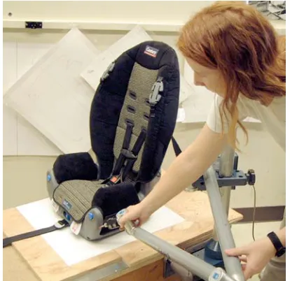
[image:5.612.59.266.326.527.2]The size and shape of each child restraint was recorded using a FARO Arm portable coordinate measurement machine. Figure 1 shows a child restraint being digitized and Figure 2 shows the resulting data. The data document the overall dimensions as well as the prominent contours, belt routing locations, harness slots, and other details relevant to the construction of the surrogates. A set of four permanent reference points was created on each restraint to facilitate data collection in the vehicle mockup. As part of the process of developing design specifications for the surrogates, these data were analyzed to determine restraint dimensions programmatically.
[image:5.612.126.199.573.687.2]Figure 1. Digitizing child restraint geometry.
Figure 2. Data point cloud for one child restraint.
The mass and center-of-mass location were determined for each restraint configuration using a scale and a balance table. Table 2 shows the means and standard deviations of masses for each of the four restraint types applicable to the surrogate development. The convertible restraints were heaviest, on average, and also showed the largest variance in mass. The rear-facing infant seats without bases were the lightest, on average, but the backless booster was lighter than the lightest infant seats.
Table 2
Child Restraint Mass Distributions by Configuration (kg)
Configuration Mean SD Min Max
Rear-facing Infant,
No Base 3.0 0.7 2.4 4.9
Rear-facing Infant,
With Base 4.9 1.1 3.9 7.2
Convertible 5.7 1.4 3.6 8.8
Backless Booster
(n=1) 1.6 -- --
--Booster/forward-facing
only 4.3 0.8 3.4 5.2
The center-of-mass (CM) measurements showed that the CMs were located fairly consistently near the geometric center of the restraints. Examination of the CM locations with the child ATDs installed in the restraints showed that the mass and mass distribution of the ATDs dominated the CM location of the ATD-plus-restraint system.
In-Seat Measurement of Child Restraints
Figure 3. Vehicle mockup for testing with seat 1 (left) and seat 2 (right).
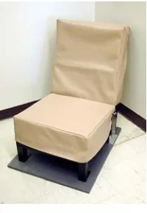
Figure 4. Standard seat.
The vehicle mockup was equipped with a standard three-point seat belt equipped with a retractor. The buckle, mounted to the seat frame with a stalk, was located in the same position with respect to H-point as the buckle in the 2000 Ford Taurus. The lower belt anchorage and D-ring were mounted on adjustable fixtures.
Test conditions were selected to span a wide range of those possible under the suppression option in FMVSS 208. The rule specifies that static evaluation of airbag suppression systems with child restraints may be conducted at full-rear, middle, and full-forward seat positions, and that testing at these seat positions (effectively, belt angles) is to be conducted with belt tensions between zero and 134 N (30 lb). Booster restraints are to be installed and the belts tensioned to between 9 and 18 N (2 to 4 lb).
Based on these requirements, the following independent variables and conditions were selected:
• child restraint and configuration (e.g., Evenflo Discovery 209 without base)
• seat type (seat 1, seat 2, or standard),
• lap-belt angle (15 or 75 degrees with respect to vertical, obtained by varying seat position and belt anchorage location), and
• belt tension (no belt, 15 lb, or 30 lb).
The child restraints were installed in the vehicle mockup using a 6YO Hybrid II, 3YO Hybrid II, or 12-month-old CRABI dummy (the 9-month TNO P3/4 was used for some preliminary testing). Table 3 lists the test matrix. Figures 5 and 6 show several installations.
In each trial, the position and orientation of the child restraint and ATD were recorded by digitizing points on the restraint and ATD with the FARO Arm. Recording the reference points on the restraint allowed the detailed geometric data previously recorded for the restraint to be aligned with the in-seat position of the restraint.
TEST RESULTS
In-Seat Measurements
The data gathered in the mockup were analyzed to determine the effects of the independent variables on the position and orientation of the child restraints. Belt angle was not found to have a consistent effect on child restraint position and attitude in the seat. On some restraints, changing the belt angle affected the orientation of the restraint, but other restraints with different belt paths and different base designs showed minimal or even opposite effects. Applying the belt with 15-lb tension moved the restraints rearward on the seat by 20 mm, on average, but increasing the belt tension to 30 lb did not have significant effects.
Back angles for both forward- and rear-facing convertibles and rear-facing infant seats were significantly different across vehicle seats due to different seat cushion angles, but did not differ with belt angles or loads.
Pressure Distribution
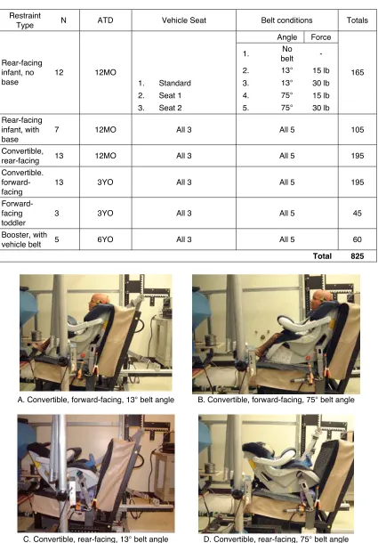
[image:6.612.110.215.225.377.2]Table 3 Test Matrix
Restraint
Type N ATD Vehicle Seat Belt conditions Totals
Angle Force
1. No
belt -2. 13° 15 lb
1. Standard 3. 13° 30 lb
2. Seat 1 4. 75° 15 lb
Rear-facing infant, no base
12 12MO
3. Seat 2 5. 75° 30 lb
165
Rear-facing infant, with base
7 12MO All 3 All 5 105
Convertible,
rear-facing 13 12MO All 3 All 5 195
Convertible. forward-facing
13 3YO All 3 All 5 195
Forward-facing toddler
3 3YO All 3 All 5 45
Booster, with
vehicle belt 5 6YO All 3 All 5 60
Total 825
A. Convertible, forward-facing, 13° belt angle B. Convertible, forward-facing, 75° belt angle
C. Convertible, rear-facing, 13° belt angle D. Convertible, rear-facing, 75° belt angle
A. Rear-facing infant seat, 13° belt angle B. Rear-facing infant seat, 75° belt angle
Figure 6. Rear-facing infant seat with detachable base shown with vehicle belt at two different lap belt angles (angle is measured on the far side).
[image:8.612.104.510.238.664.2]SURROGATE DEVELOPMENT
Concept Development
The program began without a clear indication of the number of surrogates that would be required. Initial discussions with the Joint Working Group indicated that a surrogate was believed to be unnecessary for the car bed because only one was on the NHTSA list. With the car bed excluded, surrogates were needed to represent seven distinct child-restraint configurations:
1. rear-facing infant restraints without removable bases,
2. rear-facing infant restraints with removable bases, 3. rear-facing convertible restraints,
4. forward-facing convertible restraints,
5. forward-facing-only restraints (toddler restraints with harnesses),
6. backless boosters, and 7. high-back boosters.
Representing these categories with a set of commercial restraints would require a minimum of four restraints: a rear-facing infant restraint with a base, (configurations 1 and 2) a convertible (configurations 3 and 4), a backless booster (configuration 7), and a forward-facing-only restraint that can also be used as a belt-positioning booster (configurations 5 and 8).
Although this initial categorization suggested a need for four distinct surrogates, analysis of the geometric data from commercial restraints suggested that it would be feasible to create two surrogate systems with removable components that could represent all seven categories. The convertible surrogate, consisting of a cradle component with base that can be removed and mounted at two different locations, could represent all infant and convertible configurations. A booster surrogate, with a removable back could represent the booster, forward-facing-only, and combination configurations.
Initial design assessments suggested that it might not be feasible to construct durable surrogates that also met the surrogate mass targets. Because application of the molding technology typically used to manufacture commercial restraints was not feasible for constructing surrogates, the initial surrogate concepts targeted the combined mass of the ATD-plus-restraint system. Representing the occupant shape using lightweight inserts would allow the surrogate restraint hardware to be substantially heavier and more robust than would be the case if the hardware had to meet mass targets developed from unoccupied commercial restraints.
After two generations of surrogate prototypes, the engineers at FTSS who were overseeing the hardware development identified materials and construction
methods for both the convertible and booster surrogates that would allow them to meet the unoccupied mass targets. The final prototypes are therefore intended for use with ATDs rather than special-purpose inserts.
Representing Commercial Child Restraints
The surrogates developed in this program are designed to be quantitatively representative of typical child restraints in each of the categories of interest. The target specifications for the surrogates were developed from the mean physical characteristics and performance features of the commercial restraints in each category. The rationale for using average dimensions has three major components:
1. The characteristics of a child restraint that make it “extreme” to an occupant classification system differ from system to system. The focus is therefore on the characteristics of the child restraint that are most important to the occupant classification process. In extensive discussions during Joint Working Group meetings, the industry representatives indicated that the child restraints that are problematic for classification systems vary from system to system and even across seats that are equipped with similar occupant classification systems. For one system, a narrow child restraint base might create a pressure distribution more like an adult occupant, while another system might have a problem with wide bases. Because the characteristics of a child restraint that make it “extreme” or “difficult to classify correctly” varies with the measurement technology, it is not possible to make a small set of surrogates that are quantitatively extreme for any occupant sensing and classification technology.
2. The mean value for a category (e.g., mean width for convertible restraints) is a more stable target than an extreme value (say, 95th percentile). The introduction of new commercial child restraints could change extreme percentiles much more rapidly than the mean. For the same reason, the mean values for a category are much more reliably estimated from the current sample of child restraints than are extreme percentiles.
Dimensional Specifications
The convertible surrogate was designed to the mean values of the dimensions listed in Table 4. Because the convertible is intended to represent four different restraint categories (see above), some compromises were necessary. In particular, the back length and overall height of the surrogate are the averages of the values for the infant and convertible categories. The average back length differed by about 50 mm between the two categories. The cradle component, to which the ATD is harnessed, has a back length that is midway between the values for the two categories. The cradle is then mounted on the base such that the overall height and length of the cradle+base+ATD system meets the mean targets for both the forward-facing convertible and rear-facing infant (with base) configurations. As constructed, the surrogate meets the geometric targets within a few millimeters, except that the inside width was expanded to 285 mm to allow the 3YO Hybrid-III ATD to fit easily.
Because there were fewer restraints in the categories to be represented by the booster surrogate, a greater emphasis was placed on functional equivalence than on quantitative representativeness. This direction was chosen in part because the small number of restraints that were tested included substantially different design approaches that could not be readily averaged to obtain a mean design. The booster surrogate incorporates a base designed to be typical of backless boosters and a back component that provides a frontal profile typical of forward-facing-only restraints, some of which can also be used as belt-positioning boosters. The back component does not represent the thinner, less obtrusive high-back boosters as well, but the appearance of these restraints to occupant classification systems may be similar to that presented by backless boosters, since in both cases the size and shape of the occupant dominates the geometry of the system above the base.
Specifications for Mass and Pressure Distribution
[image:10.612.318.583.95.644.2]Mass specifications for each configuration were determined by the mean masses obtained for the commercial restraints in each category. Table 2 lists the target values. As noted above, testing in vehicle seats indicated that it was not possible to create a surrogate that produced a quantitatively representative pressure distribution because the pressure distributions produced by the commercial restraints were so variable. The surrogates have square bases with length and width dimensions that are mean values for the categories and hence produce pressure distributions that are representative in terms of these basic “footprint” dimensions.
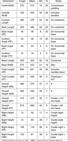
Table 4
Convertible Surrogate Specifications Based on Measurements from Facing Infant Restraints and Forward- and
Rear-Facing Convertibles
Dimension* Target Mean SD N Notes
Inside Width 270 272 16 20 Compressed padding
Outside Width
430 429 29 20 Includes handles
Cushion Length
280 276 24 20 On centerline
Back Length 490 486 56 20 On centerline
Back Angle (RF)
45 48 6 20 On horizontal base
Cushion Angle (RF)
35 38 10 20 On horizontal base
Back Angle (FF)
25 23 5 9 On horizontal base
Cushion Angle (FF)
15 16 5 9 On horizontal base
Base Length 330 329 62 16 Centerline
Base Width 275 272 51 16 Max
Total Length (RF)
650 647 46 20 Includes handles down
Total Length (FF)
550 546 39 9 Prototype = 537
Overall Height (NB)
360 276 47 11 #
Overall Height (WB)
360 348 48 7 #
Overall Height (RF)
475 473 35 7 Cradle +115 mm base
Overall Height (FF)
610 608 45 9 Cradle + 90 mm base
Bight Height (NB)
13 46 17 11 Cradle bight height
Bight Height (WB)
13 69 38 7 Cradle bight height
Bight Height (RF)
128 118 36 9 Cradle bight + base
Bight Height (WB)
103 87 36 9 Cradle bight + base
* Dimensions in mm or deg. WB = rear-facing infant without base, WB = rear-facing infant with base, RF = rear-facing convertible, FF = forward-facing convertible.
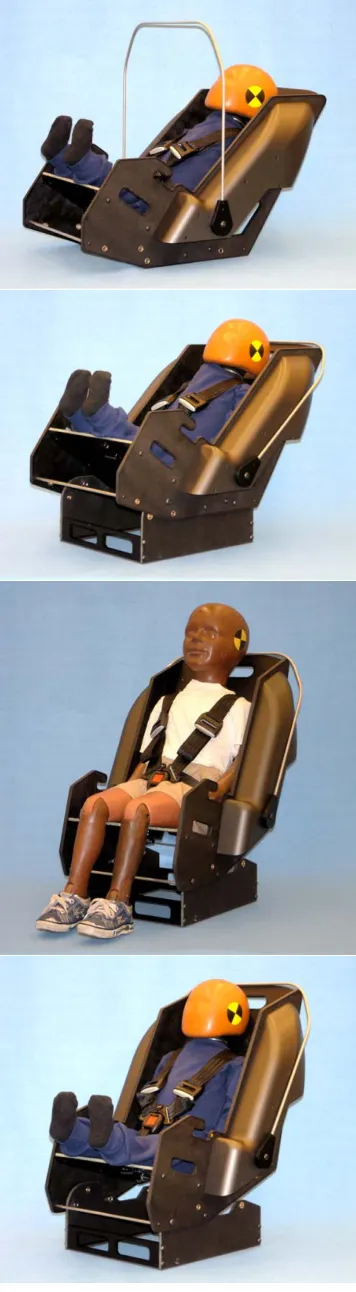
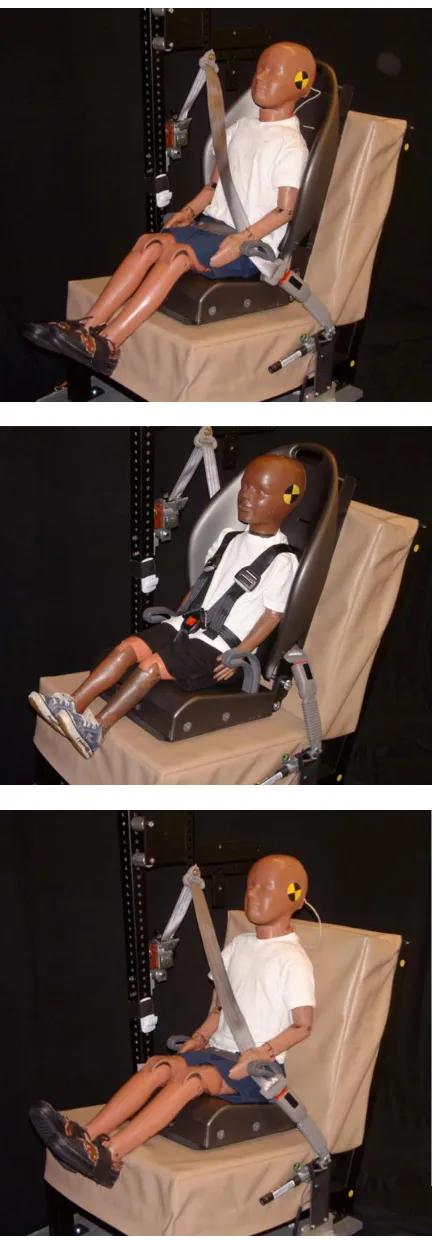
Surrogate Child Restraint Prototypes
Figures 8 and 9 show the final prototype child restraints in each of their configurations. The eight configurations identified above were represented, except that the rear-facing infant and rear-rear-facing convertible configurations are represented by a single surrogate configuration. The convertible surrogate is constructed using a foam-core carbon-fiber laminate that is light yet strong. The laminate is reinforced with plastic brackets and some metal hardware at key locations. Edges and belt paths are protected by moldings. A harness provides stability and consistent positioning for the ATD. (Note that the chest clip that would be used on a real child restraint is not included on the surrogate to facilitate ATD installation and removal.) The convertible surrogate has a base that can be removed for simulating a rear-facing infant seat without a base, or attached at two different angles to simulate a forward-facing convertible or a rear-facing restraint (convertible or infant restraint) with a base. The convertible surrogate can be used with ATDs up through the 3YO.
The convertible surrogate has three paths for the vehicle belt. For rear-facing applications, the belt can be routed under or over the thighs of the ATD, simulating typical convertible and rear-facing infant belt paths, respectively. For forward-facing applications, the vehicle belt routes behind the backrest of the restraint like many convertibles. A handle is included to allow handle-up testing with a blanket as required under FMVSS 208.
The primary components of the booster surrogate were molded using acrylonitrile-butadiene-styrene (ABS). Metal and plastic fittings are used to attach the base to the removable back component. Using the base alone simulates a backless booster. The back can be locked at a fixed angle to represent a forward-facing-only harness restraint or allowed to pivot to represent a high-back belt-positioning booster. For the forward-facing-only configuration, the ATD is secured by a harness and the vehicle belt passes through routing holes behind the backrest surface.
Figure 9. Final booster surrogate, from top to bottom, as a high-back booster, and forward-facing-only restraint, and backless booster
.
Surrogate Testing
The surrogates were evaluated for their conformance to the geometric and mass targets. As noted above, the geometric targets were met within a few millimeters. The major challenge was meeting the mass targets. Table 5 shows the final mass values for the prototype surrogates. The most meaningful way to assess the mass of each surrogate is to consider the mass of the surrogate-plus-ATD system. Table 6 lists the target values from the measurements of commercial restraints along with the prototype and associated ATD masses. Cases in which the system mass is less than the target values are not considered to be problems, because the system can be easily ballasted up to any desired weight. Of more concern is the booster and forward-facing-only configurations, which exceed the mass target. However, the target values were established from only a few commercial restraints, and the ATD-plus-surrogate system exceeds the targets by only two percent.
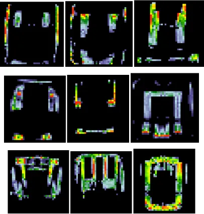
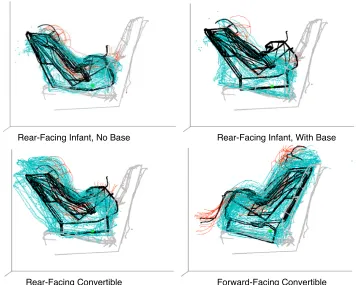
[image:12.612.318.583.454.581.2]The surrogates were also installed in each of the mockup test conditions to evaluate their performance and ease of installation. The primary consideration was the extent to which the position and orientation of the surrogate and ATD matched the data obtained with commercial restraints. Figure 10 shows the convertible surrogate geometry overlaid with the data obtained from testing with commercial child restraints in each of the four categories represented by the convertible surrogate.
Table 5
Commercial Restraint and Prototype Surrogate Masses (kg)
Category N* Min Max Mean (Target)
Prototype
RI No Base 8 2.4 4.9 3.0 3.0
RI With Base 12 3.9 7.2 4.9 3.7
Convertible 13 3.6 8.8 5.7 3.7
Backless Booster
2 1.4 1.6 1.5 2.0
Table 6
Surrogate and ATD Masses† Relative to Targets (kg)
Category Restraint ATD Total (Target)
Prototype ±%
RI No Base 3.0 10.0 13.0 13.3
--RI With Base
4.9 10.0 14.9 13.7 - 8%
Convertible 5.7 15.5 21.2 19.2 - 9%
FFO 4.3 21.4 25.7 26.4 +2%
Booster 1.5 21.4 22.9 23.4 +2% † ATD masses are 10 kg for the CRABI 12MO, 15.5 kg for the 3YO P3, and 21.4 kg for the 6YO Part 572.
When placed rear-facing without the base, the surrogate matches the size, shape, position, and orientation of the rear-facing infant restraints well. As noted above, the backrest length of the surrogate is about 25 mm greater than the average for rear-facing infant restraints, but Figure 10 shows that the surrogate represents the typical forward-most and highest points on these restraints well. The sideview profile of the surrogate, when tested rear-facing with the base, differs in the area below the backrest from most of the commercial rear-facing infant seats with bases. However, the overall height of the restraint and its forward-most protrusion match the commercial restraints well. The surrogate, as
well as some of the commercial restraints, was tested with a foam noodle placed under the rear edge of the restraint base to achieve a 45-degree backrest angle, in keeping with recommended practices for installing infant restraints (NHTSA 2001).
Some of the commercial convertibles were taller and some extended more forward than the surrogate when installed rear-facing. However, the figure illustrates a large amount of variability in these dimensions for the commercial restraints and shows that the top-of-backrest point on the surrogate lies near the center of the distribution of the same point on the surrogates. When tested forward-facing, the uppermost point on the surrogate was lower than the uppermost point on most of the convertibles, but the ATD head height in the surrogate and commercial restraints matched well. The difference in backrest height is due to the compromise described earlier that was required to obtain good fit to both the infant and convertible restraint geometry. Overall, Figure 10 shows that the size, shape, position, and orientation of the convertible surrogate lie within the range of the commercial restraints. A similar qualitative and quantitative analysis was performed with the booster surrogate. However, because of the small number and diversity of commercial restraints in the represented categories, the analyses are less meaningful and are not presented here.
Rear-Facing Infant, No Base Rear-Facing Infant, With Base
[image:13.612.124.480.412.697.2]Rear-Facing Convertible Forward-Facing Convertible
DISCUSSION
The prototype surrogate child restraints described in this paper are quantitatively representative of a wide range of child restraints with respect to geometry and in-seat performance. The surrogates were designed to mean values of a large number of geometric parameters and are subjectively and objectively typical of commercial restraints on many parameters that are likely to be important for occupant classification systems. However, the data gathered in this study illustrate clearly that any individual model of child restraint can deviate markedly from the average values in each category. The importance of this variance for occupant classification must be assessed with respect to a particular implementation of an occupant classification system. Even the same sensing technology, when applied in different vehicles, will be challenged by different restraint characteristics. The approach in the development of the surrogate child restraints, as in the development of crash dummies, has been to produce a small set of surrogates that span an important range of different characteristics (size and mass, for example), while recognizing that the true population varies much more widely.
The surrogates are intended only for non-deployment testing. They are not appropriate for testing that involves significant loading, although the surrogates are robust enough to be used in non-crash dynamic environments, such as testing the rough-road performance of a weight-based occupant sensing system.
The surrogates can be used in LATCH-equipped seating positions by use of a LATCH retrofit kit. However, the primary application of the surrogates is for testing in front seating positions that are not equipped with LATCH.
One central issue that has not been addressed in this work is whether airbag systems that would be developed and certified using the surrogates would provide performance advantages or disadvantages relative to systems developed and certified under the current FMVSS requirements. That is, if manufacturers were allowed to choose to certify their suppression systems using the surrogates, rather than the restraints listed in FMVSS 208, would the field performance of the airbag systems differ? Since no systems have yet been developed using the surrogates, no comparison data are available or can be gathered. Further study will be necessary to determine how systems designed with these surrogates perform in testing with a wide range of commercial restraints.
ACKNOWLEDGEMENTS
This research was sponsored by the Alliance of Automobile Manufacturers. The authors acknowledge the support of the Joint Working Group on Surrogate Child Restraints with representation from the Alliance and suppliers.
REFERENCES
Code of Federal Regulations (2002). Federal Motor Vehicle Safety Standard 208: Occupant Crash Protection. 49 CFR 571.208.