14th International Conference on Wireless Communications, Networking and Mobile Computing (WiCOM 2018) ISBN: 978-1-60595-578-0
Performance Analysis of Mimo-Scma Systems for 5G Communications
Hui Zhang, Yuanmei Liu, Jiawen Gu and Bin Sheng
ABSTRACT
Recently, sparse code multiple access (SCMA) is proposed as one of the important candidacies for the fifth generation (5G) radio access technique. SCMA is a non-orthogonal multiple access (NOMA) technique which allows multiple users share the same radio resource and thus increase spectral efficiency largely. In SCMA, a set of binary coded bits is mapped directly into a complex vector by use of a predefined multi-dimensional codebook. The sparsity of the codewords makes the near-optimal detection feasible through iterative message passing algorithm (MPA). The pursuit of higher spectral efficiency motivates us to study the performance of multiple-input-multiple-output (MIMO) SCMA system in this paper. Simulation results show that compared with the conventional MIMO-OFDM system, MIMO-SCMA can provide a gain up to 50% in data throughput with the aid of MPA technique.
KEYWORDS
:
Codebook, MIMO, MPA, SCMA, 5G1 INTRODUCTION
The exponential growth of wireless data services driven by mobile Internet and smart devices has raised new challenges to the current established fourth generation (4G) wireless communication systems. In order to provide greatly enhanced capacity, energy efficiency, spectral efficiency, cost efficiency, mobility, connection density, etc., with much reduced end-to-end latency, the investigation of the fifth generation (5G) wireless communication networks has been triggered. Around 2020, the new 5G mobile networks are expected to be deployed. In 5G, a lot of new network architectures and technologies, such as heterogeneous ultra-dense networks, massive multiple-input-multiple-output (MIMO), millimeter wave communications, full duplex, etc., will be investigated and applied [1]-[3].
non-orthogonal multiple access (NOMA) [5] [6]. In NOMA, more advanced receiver technique should be employed to mitigate the interferences generated by the co-existing users. Recently, sparse code multiple access (SCMA) is proposed as one of the candidacies for 5G radio access technique [7]-[10]. SCMA is a multi-dimensional codebook-based NOMA technique. It is developed based on low density signature (LDS) which is a special approach of CDMA sequence design with a few numbers of nonzero elements within a large signature[11][12]. In [8], the systematic approach to design SCMA codebooks is proposed. The multi-user SCMA technique is introduced in [9] for downlink wireless access. In [10], the energy efficiency is analyzed and the low complexity receiver design is proposed. Through the computer simulation and the measurement from prototyping system, SCMA is regarded as an energy-efficient approach for 5G wireless communication systems. On the other hand, MIMO is considered as one of the most promising breakthrough technology in wireless communications for its capability of providing high data rates (spatial multiplexing) and/or enhanced reliability (diversity) [13][14]. So, it is reasonable to use the combination of MIMO and SCMA to further increase spectral efficiency. In this paper, we introduce the MIMO-SCMA system and analyze its performance through computer simulations.
The rest of the paper is organized as follows. Section II introduces the basic idea of the SCMA technique and describes the sparse structure of the codewords and codebooks in SCMA. In Section III, we propose the signal model of MIMO-SCMA system and introduce the most used ZF/MMSE equalization technique. The sparsity of the codewords makes the near-optimal detection feasible through iterative message passing algorithm (MPA) which is described in Section IV. Numerical results are reported in Section V. The paper finally concludes in Section VI.
2 SCMA ENCODER
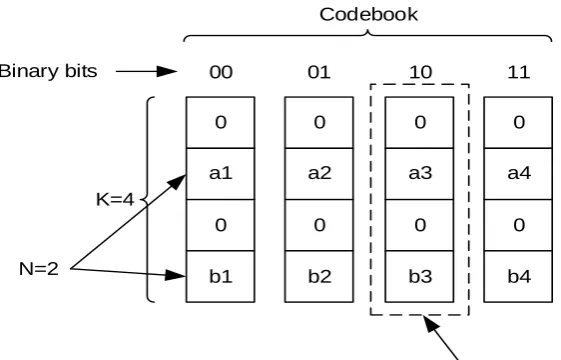
Generally, an SCMA encoder can be viewed as an extended modulator, since it maps a set of binary coded bits directly into a complex vector [10]. This complex vector is a codeword selected from a codebook and transmitted directly on the orthogonal resources. Thus, in order to transmit log2
M coded bits on Korthogonal resources, a K-dimensional complex codebook of size M needs to be predefined. In SCMA, the K-dimensional complex codewords of the codebook are all sparse vectors, since each one of them only has N < K non-zero entries and the other entries are all zeros. Compared with the conventional modulation procedure, the codebook size M can be viewed as the number of alphabets and each codeword corresponds to a K-dimensional constellation points.
to different users according to the system deployment. On the j-th layer where 0 j J 1, a K-dimensional complex codebook of size Mj is defined to transmit log2
Mj coded bits on K orthogonal resources. The K-dimensionalcomplex codewords are sparse vectors withNjK non-zero entries. All the codewords in the codebook contain 0 in the same KNjdimensions. If we assume that all layers have the same codebook size and non-zero entries, i.e.
j
M M,Nj N,for 0 j J 1, the transmitted symbols in SCMA systems can be expressed by
1
0 J
j j j
P
X x (1)
where Pj is the power allocated to the j-th layer and
0 , 1 , ,
1
TX X X K
X . xj[xj
0 ,xj 1 , ,xj
K1 ]
Tis the codeword on the j-th layer with xj 2K. xj is selected from the j-th codebook according to the input information bits on the j-th layer. Note that due to the sparsity property of SCMA encoder, some entries in xjare 0.The whole structure of SCMA symbol can be illustrated by an indicator matrix F
f f0, ,1 ,fJ1
, where fj is a K × 1 indicator vector. The k -th element of fjis denoted by fk j, and is given by [11]
,
0, then 0
; 0,1, , 1. 1, then 0
j k j
j x k
f k K
x k
(2)
the position of 1’s in fj denotes the position of non-zero entries in the codeword
of layer k. Let k and k be the set of 1’s position in the k-th row and in the j-th column in F, respectively, then we can modify (1) as
[ ]k
k j j
j
X k P x k
x (3)where x k denotes the vector stacking the signals transmitted by every layer participating in orthogonal resourcek.
the J codewords are added and the output signal vector Xis transmitted directly on K orthogonal resources. Since there are J layers transmtted on K resources, the overloading factor of SCMA system isJ K/ .
0
a1
0
b1
0
a2
0
b2
0
a3
0
b3
0
a4
0
b4
00 01 10 11
Codeword or Constellation point Binary bits
N=2
Codebook
[image:4.612.142.423.198.378.2]K=4
Figure 1. Codebook in SCMA.
3 MIMO-SCMA SYSTEM MODEL
We consider a MIMO system with M transmit antennas and M receive antennas. On the m-th antenna, a signal vector Xm Xm
0 ,Xm
1 , ,Xm
K1
is transmitted. Xmis the output of SCMA encoder and contains the codewords from J layers with the same codebook size and non-zero entries. In this paper, we assume that all the J layers and the M signal vectors are employed by one user which corresponds to a signal user MIMO-SCMA case. If the subcarrier of OFDM is used as the orthogonal resource, the channel matrix can be written as
1,1 1,2 1,
2,1 2,2 2,
,1 ,2 ,
M
M
M M M M
H k H k H k
H k H k H k
k
H k H k H k
where Hl m,
k denotes the channel frequency response (CFR) on the k -thsubcarrier between the m-th transmit antenna and the l-th receive antenna. Under the assumption that the synchronization is perfect and the channel is constant during the transmission of one OFDM symbol, the received signal on the
k-th subcarrier can be expressed by
k Es
k k
kM
Y H X V (5)
where Es is the total transmit power, X
k X0
k ,X k1
, ,XM1
k Tdenotes the transmit signal and V
k V k V k0
, 1 , ,VM1
k Tis the additive white Gaussian noise (AWGN) with zero mean and covariance of 2n
I, where I indicates the identity matrix. In this paper, we assume that the complex-valued channel matrix H
k has i.i.d. Gaussian entries with zero mean and unit variance and all the channel matrices on the K subcarriers are identical, i.e.
0
1
KH H H . For the sake of notation simplification, we drop the
index k from H
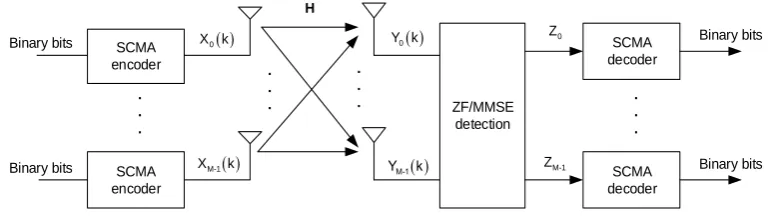
k in the following analysis. Figure 2 shows the blockdiagram of the described MIMO-SCMA system.
Assume the channel is unknown to the transmitter but perfectly known to the receiver. In this case, uniform power allocation at transmitter is preferred. If we set all the powers of different layers on the different antennas to be identical, i.e.
0 1 J 1
P P P P, the transmit power of each antenna is equal to JP and the total power is thusEs MJP.
SCMA encoder
SCMA encoder
. . .
Binary bits
Binary bits
0
X k
M-1
X k
H
. . . .
. .
0
Y k
M-1
Y k
ZF/MMSE detection
SCMA decoder SCMA decoder
. . .
0
Z
M-1
[image:5.612.104.491.459.568.2]Z Binary bits Binary bits
Figure 2. MIMO-SCMA system.
3.1 ZF Equalization
complexity. Besides the ML criterion, the zeroforcing (ZF) and minimum mean square error (MMSE) detections are linear equalization-based methods. They are low-complexity and simple to implement with degraded performances. In ZF detection, the received signal is multiplied by an equalization matrixGZF, which is the Moore-Penrose pseudo-inverse of H,
1
ZF ( )
H H
G H H H (6)
where (·)−1 and (·)H denote inverse matrix and hermitian transpose, respectively. After ZF equalization, we obtain
1
ZF
H H
k k k
Z G Y H H H Y (7)
where Z k Z0 K ,Z K1 , ZM1 K Tis the estimate of the transmitted symbol
vector. According to [15] [16], the signal-to-noise ratio (SNR) of the k-th transmitted signal can be expressed by
2
2 1
2
2 2
,
m k s s
m H
n m m j s n m m
j m
E E
M E M
g h SNR
g g h H H
(8)
where gm denotes the m -th row of the equalization matrix GZF and hk represents the m-th column vector of the channel matrixH.
3.2 MMSE Equalization
The concept that MMSE detection uses is to minimize the mean square error
2
E GY k X k , where G denotes the equalization matrix. The MMSE detection considers the noise variance and reduces the noise enhancement by using the minimum mean square error equalization matrix obtained from
1 2
MMSE
H n H
s M
E
G H H I H (9)
The transmitted symbol vector estimate of the MMSE detection is written as
MMSE
2 1
.H n H
s M
k k k
E
After MMSE equalization, the received signal is decoupled into M substreams with output SNR
2
1 2
1, 0 1
s n m H n s mm E M m M M E SNR
H H I
(11)
4 MPA DECODER
From K transmitted symbol vector estimates, we obtain M SCMA symbol estimates. They are Zm Zm
0 ,Zm
1 , ,Zm
K1
, 0 m M1 . These SCMA symbol estimates are then fed into the following independent MPA decoder to retrieve the input binary bits. Without loss of generality and for natation brevity, we drop the index mfrom Zm in the following analysis.Given theZm, the joint maximum-a-posteriori (MAP) detection of Xmcan be written by [10] [11]
0 1 , , 1
ˆ arg max
J p
X
X X Z (12)
where j
represents the codebook of the j-th layer. MAP detection requires a globe search over the joint codebook space of J layers 0 1 J 1
m m m
to minimize the probability that all layers are detected correctly. Due to the sparsity property of SCMA codewords, the MAP detector problem can be translated into marginalize product of functions (MPF) problem much more efficienctly. According to [11], the codeword xjcan be estimated by
0 1 1
[ ]
ˆ arg max j J j j k j k
P p Z k
w X x wx X x (13)
where wis the selected codeword and
1
0 J
j j
P X
P x .The MPF problem can be solved by message passing algorithm (MPA) proposed in [11] onto the underlying factor-graph
U C,
. Factor-graph is the bipartite graph representation of the factorization defined in (13). In this factor graph, the transmitted symbolsxj, j0,1, ,J1 and the observationZ k
,0,1, , 1
respectively. At the function nodeck, the local observation Z k
is made andgiven by
[ ]
[ ] 22 2
1 1
exp 2 2
k k
n n
p Z k Z k
x x (14)
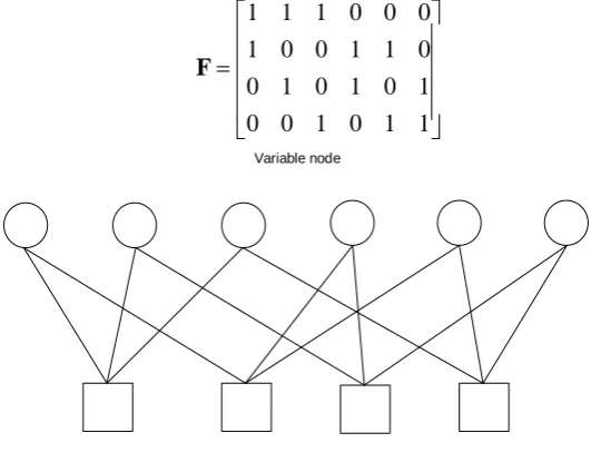
Figure 3 shows an example of factor-graph representation for a SCMA encoder with K = 4, N = 2 and J = 6. The indicator matrix is assumed to
1 1 1 0 0 0 1 0 0 1 1 0 0 1 0 1 0 1 0 0 1 0 1 1
F (15)
Variable node
Function node
Figure 3. Factor-graph representation.
5 SIMULATION AND RESULTS
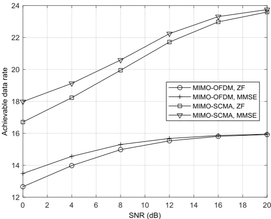
[image:8.612.164.430.227.439.2]0.1759j 0.4873 −0.6156j − 0.4873 + 0.6156j − 0.1392 + 0.1759j; 0 0 0 0; 0 0 0 0]; [0 0 0 0; 0 0 0 0; 0.7851 − 0.2243 0.2243 − 0.7851; −0.0055 − 0.2242j − 0.0193 − 0.7848j 0.0193 + 0.7848j 0.0055 + 0.2242j]; [−0.0055 − 0.2242j − 0.0193 − 0.7848j 0.0193 + 0.7848j 0.0055 + 0.2242j; 0 0 0 0; 0 0 0 0; −0.6351 +0.4615j 0.1815 − 0.1318j − 0.1815 + 0.1318j 0.6351 − 0.4615j]; [0 0 0 0; 0.7851 − 0.2243 0.2243 − 0.7851; 0.1392 − 0.1759j 0.4873 − 0.6156j − 0.4873 + 0.6156j − 0.1392 + 0.1759j; 0 0 0 0]. For the purpose of comparison with the OMA systems, a 2 2 MIMO-OFDM with QPSK modulation is also simulated. In simulation, ideal channel estimation is assumed and no channel coding is considered. The number of iteration cycles in MPA is set to 5.
Figure 4 shows the performance comparisons as a function of SNR in term of achievable data rate. Achievable data rate is defined as the averaged successfully received bits on every four subcarriers. From Figure 4, we can see that up to 50% gain in data throughput can be achieved by the MIMO-SCMA system with the aid of MPA technique, when compared with MIMO-OFDM system.
Figure 4. Achievable data rate.
6 CONCLUSIONS
near-optimal detection feasible through iterative MPA. In this paper, the basic principle of the SCMA encoder and decoder are introduced and the performance of MIMO-SCMA system is analyzed through computer simulations. Compared with MIMO-OFDM system, MIMO-SCMA can provide a gain up to 50% in data throughput with the aid of MPA technique which demonstrates that MIMO-SCMA is a promising radio access technique for the upcoming 5G communication networks.
ACKNOWLEDGEMENTS
This work is supported by the Hong Kong, Macao and Taiwan Science & Technology Cooperation Program of China (2014DFT10290 and 2016YFE0123100).
REFERENCES
1. X. H. You, Z W Pan, X Q Gao, S M Cao, and H Q Wu. 2014. “The 5G mobile communication: the development trends and its emerging key techniques,” Science China: Information Sciences, 2014, 44: 551–563
2. T. Wen, P. Y. Zhu. 2013. “5G: A technology vision,” Huawei, 2013. http://www.huawei.com /en/ about-huawei/publications/winwin-magazine/ hw-329304.htm
3. C. X. Wang, F. Haider, and X. Q. Gao, et al. 2014. “Cellular architecture and key technologies for 5G wireless communication networks,” IEEE Commun Mag, 2014, 52: 122–130.
4. E. Dahlman, S. Parkvall, J. Skold. 2014. 4G: LTE/LTE-advanced for mobile broadband. 2nd ed. Waltham, MA, USA: Elsevier.
5. J. Choi. 2014. “Non-orthogonal multiple access in downlink coordinated two-point systems,”
IEEE Commun. Letters, 2014, 18(2): 313–316.
6. Z. G. Ding, M. G. Feng, and H. V. Poor. 2014. “On the performance of nonorthogonal multiple access in 5G systems with randomly deployed users,” IEEE Signal Process. Letters, 2014, 21(12): 1501–1505.
7. H. Nikopour, H. Baligh. 2013. “Sparse code multiple access,” IEEE 24th PIMRC, 2013, 332–336.
8. M. Taherzadeh, H. Nikopour, A. Bayesteh, and H. Baligh. 2014. “SCMA codebook design,” IEEE 80th VTC, 2014, 1–5.
9. H. Nikopour, E. Yi, A. Bayesteh, K. Au, M. Hawryluck, H. Baligh, and J. L. Ma. 2014. “SCMA for downlink multiple access of 5G wireless networks,” IEEE Globecom, 2014, 3940–3945.
10. S. Q. Zhang, X. Q. Xu, L. Lu, Y. Q. Wu, G. N. He, and Y. Chen. 2014. “Sparse code multiple access: an energy efficient uplink approach for 5G wireless systems,” IEEE Globecom, 2014, 4782–4787.
11. R. Hoshyar, F. Wathan, and R. Tafazolli. 2008. “Novel low-density signature for synchronous CDMA systems over AWGN channel,” IEEE Trans Signal Process, 2008, 56: 1616–1626. 12. R. Hoshyar, R. Razavi, and M. AL-Imari. 2010. “LDS-OFDM an efficient multiple access
technique,” IEEE 71th VTC, 2010, 1–5.
14. A. Osseiran, F. Boccardi, V. Braun, et al. 2014. “Scenarios for 5G mobile and wireless communications: the vision of the METIS project,” IEEE Commun. Mag., 2014, 52(5): 26–35.
15. S. Kay. 1993. Fundamentals of Statistical Signal Processing: Estimation Theory. Englewood Cliffs: NJ: Prentice-Hall.