http://dx.doi.org/10.4236/epe.2013.510069
Optimum Distribution of Two Different Phase Change
Materials between Various Components of Roof
Air-Conditioned Room, Suitable to Reduce
Annual Energy Consumption
Bouchra Abouelkhayrat*, Hamid Hamza, Jawad Lahjomri, Abdelaziz Oubarra Laboratory of Mechanics, Faculty of Sciences Ain Chock, Hassan II University,
Casablanca, Morocco
Email: *[email protected]
Received November 6, 2013; revised December 6, 2013; accepted December 13, 2013
Copyright © 2013 Bouchra Abouelkhayrat et al. This is an open access article distributed under the Creative Commons Attribution License, which permits unrestricted use, distribution, and reproduction in any medium, provided the original work is properly cited. In accordance of the Creative Commons Attribution License all Copyrights © 2013 are reserved for SCIRP and the owner of the intellectual property Bouchra Abouelkhayrat et al. All Copyright © 2013 are guarded by law and by SCIRP as a guardian.
ABSTRACT
Obviously, the outside annual climate change caused either by a major solar input during the hottest period or by a temperature drop during the coldest period leads to discomfort inside buildings. This effect can be reduced by storing heat transmitted in phase change materials (PCM) as latent heat, in order to ensure a good situation of thermal comfort during all months of the year. In this work, thermal behavior of two roofing systems is studied. One roof is constituted only by usual materials in building. In the other, two phase change materials (PCM) are introduced according to three configurations. Study is interested to assess incorporation effect of two PCMs within the roof and to evaluate the opti-mum locations to reduce the energy consumption of air-conditioned room. Mono-dimensional numerical model vali-dated analytically and experimentally, is used to carry out a parametric analyzes to determine characteristics of the lay-ers in which the roofs are formed regardless of external climate effect. Numerical calculations are performed for three configurations of roof. Results show that insertion of phase change materials in roof provides best energy consumption saving regardless annual climate change. Generally, the three configurations lead to different results, depending on the combination of PCMs. This difference becomes less important when selection of PCMs takes account the thermal com-fort level and temperatures of hottest and coldest periods.
Keywords: Phase Change Material (PCM); Thermal Comfort; Multilayer Roof; Energy Consumption
1. Introduction
Recently, modern lifestyle leads to a huge problem of energy consumption worldwide. Especially, the exce- ssive climatic conditions produce discomfort situation, which requires frequently using air conditioning systems, subsequently results in increasing of domestic energy con- sumption. Hence, this involves an increasing interest in thermal correction of building designs to create comfort situations. In order to save this energy exhaustion, among best known solutions proposed are: Use insulated walls/ roofs in building [1], use of reflective color outdoor sur- faces [2] and use of energy storage devices in the build- ing structure [3]. As it is predicted in the literature, the
mismatch that is often found between the supply and demand of energy can be corrected by these systems which provide a valuable solution. This is concerned against waste energy by storing and to restore it after, which are as important as developing new sources of energy. Hence the thermal energy storage systems such as phase change materials (PCMs) provide the potential to attain energy savings, which in turn reduce the envi- ronment problems due to conventional energy use.
Currently, the research about use of the phase change material (PCM) was increasingly under consideration especially for latent heat accumulator [4,5], solar heating system [6], building energy conservation and waste heat recovery [3,7,8]. The phase change material use, aims to reduce waste of energy by storing and restoring it after,
when it is needed to consumption. Due to its important thermal energy storage as latent heat of fusion, that is advantageous over sensible heat because of its high stor- age density and the isothermal characteristics of charging and discharging process. Moreover, latent heat storage has the capacity to store heat of fusion at a constant or near temperature which corresponds to the phase change material (PCM). In fact, there are large numbers of PCMs [9,10] that melt and solidify at a wide range of temperatures, making them attractive in a number of building applications [10].
Generally building thermal performance evaluation of roof envelope with or without PCM has focused to opti- mize a suitable roof for air-conditioned rooms. Scientist research about this problem is carried out in the periodic external climatic conditions, depending on the building material choice, and also the internal level of comfort re- quired [11-15]. The procedure applied by many authors is numerical study of one dimensional heat transfer through a wall/roof under convection boundary condi- tions, for air-conditioned rooms [5,7,16,17]. For roof with PCM, the works carried out a parametric study us- ing enthalpy formulation taking into account heat latent of phase change material. Among technical procedure to operate the PCM in building there are two principal ways. Whatever, composites such as the PCM mixture with other construction compound called shape-stabilized PCM (SSPCM) [18] or well PCM coated in a thin metal con- tainer [19].
The main reason of using PCM in building [8,20,21] as energy storage devices in multilayer wall/roofs is to de- crease the external climate effect on the inner surface of roof including PCM. Thus the heat energy will be absor- bed both latent and sensible heat. But, this is not checked during all months of the year because the melting tem- perature of one PCM is not suitable for annual variations outside temperature. Hence, providing constant tempera- ture in air-conditioned room without spending a large energy amount throughout the year requires to investi- gate the effect of two different PCMs in roof/walls building. This trend is expected narrowing of the heat transferred to local for all seasons. This technique was investigated by Pasupathy and Velraj [15]. The authors studied, firstly one layer of PCM kept in a residential building roof, after that, two PCMs with different melt- ing points are incorporated in the roof. This solution leads to roof with two PCMs thicker than one without PCM; however, the effect of PCMs location is not stud- ied.
Hence, this work studies the improvement of classical roof taken as reference, constituted by usual building ma- terials. Two different phase change materials are intro- duced as several combinations of PCMs between refer- ential roof layers in different positions. Thus, energy consumption to maintain the constant indoor air tem-
perature is used as evaluation parameter. This parameter has also been used as criterion for insulation efficiency studied by G. Barrios et al. [1,22], and the effect of PCM ceiling panels investigated by N.A. Yahaya et al. [23]. Then, the energy consumption will assess for roofs kept in same total thickness with and without PCMs. The nu- merical simulation of roof thermal behavior over all year allows the achievement of annual energy consumption amount of air-conditioning room. Further, in order to determine optimal position of PCMs, this work is per- formed for three different configurations composites. The results obtained are taken for selecting the suitable combi- nation of PCMs and also the optimal configuration. This is allows determining the criteria for selecting the PCMs likely to ensure the energy economy specified before.
2. Illustration of the Problem Studied
2.1. Statement of Roofs
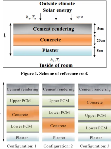
The roof geometry used as reference is shown schema- tically in Figure 1. It is multilayer structure of thickness
L = 30 cm, consisting of Plaster eP = 5 cm, Cement Ren-
dering eCR = 5 cm and Concrete of thickness eC = 20 cm.
The roof is studied under external climatic conditions (convection, solar radiation) while its internal surface is in contact with a local temperature conditioned. Latitude and longitude coordinates used to identify roof site de- signed to be in Casablanca city are respectively: Latitude 33˚32'N and Longitude 7˚41'W.
The improvement of reference roof undergoes this conditions during all year, requires to incorporate two phase change materials (PCM1 and PCM2) of thicknesses
em1 = em2 = 3 cm. The integration of these materials is
achieved without changing the basic structure. For this, the thickness of the concrete is maintained constant eC =
20 cm, but the layers of Plaster and Cement Rendering are reduced from 5 cm to 2 cm. When PCMs are inserted, the thickness of Plaster and Cement Rendering becomes respectively eP = 2 cm and eCR = 2 cm.
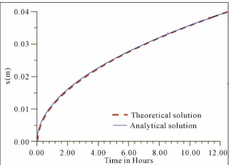
Hence three configurations schematized in Figure 2
are considered according to location of phase change ma- terials integrated in reference roof. In configuration 1 the both PCMs are separated by concrete, while configura- tions 2 and 3 are respectively for the cases where the PCMs are above and below concrete.Each PCMs pair, leads to two ways of insertion for each configuration by inverting the PCMs which result six combinations. These different combinations are considered and studied in or- der to ensure minimum energy consumption provided by the air conditioner, knowing that this investigation occurs during 12 months. Thus, it is expected that the effect of the external environment will be less noticeable on the roof due to the presence of PCM.
Figure 1. Scheme of reference roof.
Figure 2. Positions of PCMs integration in referential roof.
lead to development of the following assumptions to de- fine the numerical model:
In your paper title, if the words “that uses” can ac- curately replace the word “using”, capitalize the “u”; if not, keep using lower-cased.
The heat conduction in the composite wall is one di- mensional and the end effects are neglected.
The PCM is homogeneous and isotropic.
The interfacial resistances are negligible.
All physical properties of both liquid and solid mate- rial are constant.
The volume expansion is neglected during melting of the PCM.
The effects of natural convection in the liquid phase of the PCM are negligible. This hypothesis is admi- tted for thin PCM thickness [5,24]. In this study, the aspect ratio is ~0.01.
2.2. Mathematical Model
Solving the equation of problem for different roof ma- terials and PCM is given by Equation (1). Hence the di- mensional equation of energy in different parts of system is written as:
2
2
T f
t t
is the thermal diffusivity of i-th material layer, T
the temperature, t the time, and x the position which varies inside the layer.
The term f C is present only for phase change material PCM during melting at T m, characterized by melting ratio
T
0,1f , such f is the latent heat of PCM and C is the specific heat.
The melting thermal diffusivity of PCM during melting is calculated using the following equations:
1
T x
(1)
s f lf
.
Such as the indices s, and indicate respectively solid and liquid phase.
l
Continuity of temperature and flux are applied in all unions between i-th and (i+1)-th layers according Equa- tions (2) and (3) respectively.
Ti i i1
Ti1 i i1 (2)1 1
1 1
i i
i i
i i i i
T T
K K
x x
(3)
where: Ti, Ki and Ti1, Ki1 are respectively tem-
peratures and thermal conductivities of the i-th and (i+1)-th layers respectively. i i1 denotes that the calculation is evaluated in the interface between the i-th
and (i+1)-thlayers.
The boundary conditions on both sides of the roof are respectively:
Indoor boundary condition :
1 0
0
int int x x
T
K h T T
x
(4)
where K1 is the thermal conductivity of the indoor lay-
er and hint is the indoor heat transfer coefficient, Tint is the indoor air temperature and Tx0 is the temperature on the indoor surface.
Outdoor boundary condition:
out out x L S ES x L
T h T T I R
x
KN (5)
where KN is the thermal conductivity of the outdoor layer and hout is the outdoor convection coefficient,
x L
T is the temperature on the outdoor surface, Tout is the outdoor air temperature. is the solar absorptivity of the outside surface, IS is the solar radiation and
ES is the radiation exchange with the sky. These last
R
parameters affecting outdoor boundary condition are calculated for horizontal roofs in Casablanca by using the ASHRAE model [25,26].
2.3. Validation of Numerical Solution
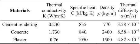
The Before presenting the numerical results for the phase change system, the numerical code must be validated by comparison with analytical solution available in the lite- rature.
First, the phase-change model was checked against the classical Newman problem. The PCM is initially at melt- ing temperature i m in semi-infinite long rectangu- lar with a uniform cross section. At , the surface is kept at a temperature e m and liquefaction of PCM takes place. Position of solid-liquid interface versus time is calculated by numerical code and compared to its ana- lytical values given by the function [17]:
T T
T
0
t
T
2y
where is an unknown to be determined by solving the following Equation (6) [17]:
2
expπ
l
e m
C
erf T T
(6)Result of comparison between numerical and analy- tical solutions is reported in Figure 3. It can be seen that
the present model agrees well with the results of this study.
The second validation reported in Figure 4 is a com-
parison of the numerical code with the numerical and experimental results obtained by the study carried out by Amir et al. [3] using the paraffin n-octadecane such as phase change material of melting temperature Tm = 28˚C. The operation of storing electrical energy during about four hours is followed by a release of energy during six- teen hours. The end of the process of storage and the beginning of energy releasing appear in the Figure 4 by
a peak representing the maximum value of the PCM tem- perature. The numerical code is suitable to the same op- erating conditions carried on a building configuration used in thermal analysis electric heating floor panels with daily heat storage [3]. The results of the comparison be- tween the experimental and numerical temperatures pro- files within the PCM show good agreement between the results of this study and the current numerical model. The results depicted in Figure 4 prove that their reliabil-
ity and accuracy are assured; furthermore this numerical model can give the results to a multilayer roof/wall.
3. Parametric Study and Discussion
Simulation results of the developed numerical code are relating to all months of year. The various configurations shown schematically above (Figure 2) as well as refer-
ence roof (Figure 1) have been treated for similar ther-
mal conditions imposed.
The internal temperature is expected to be maintained at a constant temperature whereas the ex- ternal temperature follows a sinusoidal temporal evolu- tion which profile is given for extreme period as follows:
20 C
int
[image:4.595.308.540.83.250.2]T
[image:4.595.309.538.279.438.2]Figure 3. Evolving of melting front position with time.
Figure 4. Temperature profile during a cycle of storage- release.
In summer (hottest period):
27 13 sin 4
ext
T t
(7)In winter (coldest period):
13.5 8.5 sin 4
ext
T t
(8)With: , are respectively daily period and pul- sation.
In addition to the effect of the variation of the outdoor temperature, the terrace is subjected to the action of solar radiation, approached by the Mediterranean ASHRAE model [25,26].
The effect of these outside conditions at inside roof surface appeared as a heat flow fluctuations. The fluctua- tions transfer leads to important energy consumption of air conditioner able to ensure an inside constant tem- perature. This energy consumption is calculated as an average daily at inside roof surface by Equation (9) and also its annual accumulation defined by Equation (10).
Daily Daytime
0
int int
h T x T t
x = 0 corresponds to the inner section of the roof
12
Annual Daily 1
m
i i
(10)Such, that i means the month that varies from January until December.
3.1. Study of Reference Roof
[image:5.595.308.539.112.185.2] [image:5.595.309.539.224.295.2]The referential roof is constituted by three different building materials of physical properties summarized in
Table 1. This system of roof without PCM undergoes
outdoor periodic climate conditions which affects interior comfort. Therefore the annual energy consumption, de- fined by Equation (10), needed to keep the indoor air temperature constant 20˚C, reached 3.686 kWh/m2.
Hence it is interesting to check whether the inclusion of PCMs layers at the interfaces of the roof schematized above in Figure 1 can reduce this energy consumption.
In order to determine phase changes materials most sui- table to reduce the consumption of energy, it requires carrying out a thermal behavior analysis of the referential roof. Temperature evolution studied for two extreme periods; one is hottest, while other is coldest, allows de- termination of temperature range applicable in all months of year. Levels to take the temperature are chosen ac- cording for location designed to insertion of phase chan- ge materials that are localized between the concrete and cement rendering, and also between the concrete and plaster. The results summarized in the following Table 2
show that the choice of the most suitable PCM for the warm period is that which at a melting temperature be- tween 24˚C and 34˚C, while the coldest period requires a choice between 17˚C and 23˚C. Hence, it is provided that choice of two PCMs having melting temperature between 17˚C and 34˚C, can achieve most suitable result during all the year. Finally, PCMs added are then a combination of PCMs of melting temperature in range of hottest pe- riod with other corresponds coldest period.
Although the literature [9,10] presents a variety of phase change materials, an unavailability of certain phy- sical properties necessary for the numerical study limits the choice of operating PCMs. The phase change materi- als selected are given in Table 3. There are two kinds of
PCMs: one suitable for space cooling and other suitable for space heating. Therefore, it is convenient to modify the design of the referential roof, by inserting two layers of materials as the phase change material (PCM) can store the both hot and cold energy in order to restore it later for minimizing the transmission of outside climate energy in indoor.
Indeed for a conventional roof without PCM, the amount of consumption energy is obviously influenced by the evolving external thermal conditions but also there is physical properties effect of roof components. Cer-
Table 1. Physical properties of different building materials used in the study.
Materials
Thermal conductivity
K (W/m·K)
Specific heat C (kJ/kg·K)
Density
(kg/m3)
Thermal diffusivity
α (m2/s)
Cement rendering 0.230 835 770 3.58 × 10⁻⁷
Concrete 1.730 840 2400 8.58 × 10⁻⁷
Plaster 0.76 1050 1500 4.82 × 10⁻⁷
Table 2. Temperature evolution for two extreme periods; one is hottest, while other is coldest.
Temperature in hottest
period (˚C) coldest period (Temperature in ˚C) Location designed to
insertion of PCM
Min Max Min Max Concrete/Plaster 24.24 27.06 18.89 21.18 Concrete/Cement
rendering 25.04 33.84 17.42 22.57
tainly, the thermal inertia of traditional building com- pounds used in this study, cheek an important role in delaying the transition of heat flow fluctuations. From
Table 1, it is found that the values of thermal diffusivity
and thermal conductivity of concrete which possesses thicker part of the roof are higher compared to same physical properties of cement rendering and plaster. Hence lower thermal conductivities and diffusivities of plaster and cement rendering lead to protection around concrete layer against outside climate conditions. This protection can be improved by replacing part of the Ce- ment Rendering and Plaster by a same size of PCMs lay- ers with requirement to keep the same total thickness of the roof. According to Table 3, the thermo physical pro-
perties of PCMs provide generally a low thermal conduc- tivity and a less thermal diffusivity which allows to im- provement prediction of the thermal behavior roof.
3.2. Comparative Study of the Annual Internal Flux of Different Combinations of Phase Change Materials (PCM)
Numerical study focuses on roof thermal behavior simu- lation for each combination of selected PCMs. The aim is to determine that which be able to reduce the effect of outside climate energy fluctuations during all year on the air-conditioning energy consumption. The configurations schematized in Figure 2 are carried out in periodic re-
Table 3. Physical properties of selected PCMs.
PCMs temperatureMelting T
m(˚C)
Latent heat λf(kJ/kg)
Thermal Conductivity
K(W/m·K) Specific heat C(kJ/kg·K)
Density
(kg/m3) Diffusivity Thermal α (m2/s)
PCM for Coldest Period
S19 [10] 19 160 0.430 1.90 1520 1.49 × 10⁻⁷
Clim Sel C21 [10] 21 144 0.7(liquid) 0.5(solid) 3.6 1380 1.41 × 101.01 × 10−−77 (liquid) (solid)
S23 [10] 23 175 0.540 2.2 1530 1.60 × 10⁻⁷
PCM for Hottest Period
Clim Sel C24 [10] 24 126 0.7 (liquid) 0.5 (solid) 3.6 1380 1.41 × 101.01 × 10−−77 (liquid) (solid)
RT25-RT30 [9] 26.6 232 0.18 (liquid) 0.19 (solid) 1.41 (solid) 1.8 (liquid) 749 (liquid) 785 (solid) 1.34 × 101.72 × 10−−77 (liquid) (solid)
Polyethelene
glycol 900 [9] 34 150.5
0.19 (liquid) 0.19 (solid)
2.26 (liquid) 2.26 (solid)
1100 (liquid) 1200 (solid)
0.76 × 10⁻⁷ (liquid)
0.69 × 10⁻⁸ (solid)
swapping of PCM selected, such as:
Configuration 1: Both PCMs are separated by concrete layer.
Configuration 2: Both PCMs are above concrete layer. Configuration 3: Both PCMs are below concrete layer. Further, these last configurations are compared with referential roof without PCM under the same external conditions and for the same thickness of concrete layer.
The annual energy consumption, defined by equation 10, is calculated for all PCMs combination formed in each configuration and also for roof without PCM. The annual accumulation of the monthly average of daily heat flow is given in (kWh/m2), at the inner face of the roof
that is mean in contact with the room at x = 0, where the temperature is kept at 20˚C. Hence its data summarizes
Annual as total of daily energy Daily calculated for
each months by Equation (9), at the inner surface for different cases.
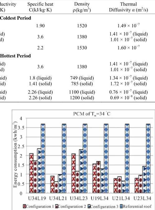
Figure 5. Combinaisons of PCM of Tcoldest period. m = 34˚C with PCMs of
The first observation is that the combination of the same PCM with other PCMs gives different results in terms of energy consumption, to ensure internal tem- perature fixed at 20˚C. This is also remarkable when go- ing from one configuration to another for the same com- bination. Generally the annual energy consumption is often shows that the integration of PCMs, improves the residential buildings roof by reducing the energy con- sumption. This decrease can reach until 0.61 kWh/m2,
when PCM of melting temperature 34˚C is up and PCM of melting temperature 21˚C is lower in configuration 2 such as the both PCMs are over concrete, while the ref- erential roof without PCM uses about 3.686 kWh/m2, i.e.
reduction of 83%. The importance of studying these combinations in details is summarized in the next section.
Figure 6. Combinaisons of PCM of Tm = 26.6˚C with PCMs of coldest period.
Annual
development for the three configurations and for referential roof.
3.3. Combination Analysis
Generally, the obviously observation as shown in Fig- ures 5-10 is that for roof without PCM, energy amount is
greater than roof with two layer of different PCMs. The In order to assess the study mentioned previously, the
results achieved are presented in Figures 5-10. These
[image:6.595.308.539.479.638.2]Figure 7. Combinaisons of PCM of Tm = 24˚C with PCMs of coldest period.
Figure 8. Combinaisons of PCM of Tm = 23˚C with PCMs of hottest period.
Figure 9. Combinaisons of PCM of Tm = 21˚C with PCMs of hottest period.
integration of PCMs in the roof is always suitable and may even decrease the energy necessary to maintain constant local temperature.
The facts are confirmed for combination of PCMs with
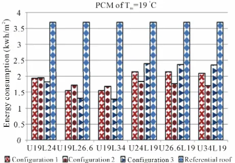
Figure 10. Combinaisons of PCM of Tm = 19˚C with PCMs of hottest period.
significant advantage compared with the roof without PCM regarding the annual energy consumption Annual.
Even that is true, but it is not always possible to have a significant reduction as shown results obtained when the PCM of melting temperature 19˚C is combined with the selected PCM for the hottest period. Whereas the inser- tion of two PCMs with different melting temperature is very important, it is necessary to realize a study corre- sponding to thermal behavior of roof undergoes incorpo- ration of PCMs. This thermal behavior evolution is in- fluenced by other physical properties besides the melting temperature as latent heat and thermal diffusivity.
Because PCMs are selected according extreme periods, results will be discussed as two sub-paragraphs: one for the hottest period and other for the coldest period. Such a similar notation as U34L19 is used in abscissa axis, means: Upper PCM of melting temperature 34˚C and Lo- wer PCM of melting temperature 19˚C.
3.3.1. Combinations of PCMs Selected for Hottest Period
Figures 5-7 illustrated annual consumption energy ac-
cording to different combinations of PCMs selected for hottest period with the other PCMs, allow to comparison of three studied configurations.
This shows that location of PCMs having a higher melting temperature (Tm= 34˚C, Tm = 26.6˚C, Tm = 24˚C) , above PCMs with lower melting temperature (Tm = 23˚C,
Tm = 21˚C, Tm = 19˚C) is preferred for configuration 2 followed by the configuration 1, while configuration 3 is placed thirdly.
[image:7.595.58.288.485.648.2]uration 3, which behaves differently, it is obvious that the combination of PCMs selected for hottest period with PCMs of Tm = 19˚C and Tm = 21˚C, leads a saving of energy better than configuration 1 and 2. For PCM of Tm = 23˚C results by these PCMs mentioned previously show that configuration 3 is third in front of config- urations 1 and 2.
Generally, for the three configurations, when PCMs selected for hottest period are above of all PCMs of cold- est period, the energy consumption is rising compared to the inverse permutation. So the location of PCMs of the upper melting temperature, below to PCMs of lower melting temperature, leads to save the energy designed to provide thermal comfort in room interior.
3.3.2. Combinations of PCMs Selected for Coldest Period
Evolution of the annual energy consumption of air con- ditioners providing Tint = 20˚C, is evaluated by testing the PCMs selected to reduce this energy in the coldest period. Firstly the Figures 8-10 show that location of
PCMs having a higher melting temperature, above PCMs with lower melting temperature is preferred for config- uration 2 followed by the configuration 1, whose config- uration 3 is placed thirdly. Accordance this order, due to melting temperature decrease of PCMs hottest period. The results of configurations 1 and 2 begin to approach until to have almost a same value, specially for the PCM
Tm = 23˚C.
Secondly, the location of PCMs having a higher melt- ing temperature below PCMs with lower melting tem- perature (Tm = 21˚C and Tm = 19˚C) is preferred for configuration 3 followed by the configuration 1, whose configuration 2 is placed thirdly. Regarding PCM of melting temperature Tm = 23˚C, the classification of con- figurations is respectively 1, 2 and 3. Accordance this classification, due to melting temperature decrease of PCMs of hottest period, the results of configurations 1 and 2 start approximated until to have almost a same va- lue, exept for the PCM of Tm= 34˚C.
The results mentioned in Figures 8-10 have confirmed
for PCMs selected for coldest period the same remark previously concluded, but with one exeption. The loca- tion of PCMs having low melting temperature above to PCMs with high melting temperature is relevant, except PCM of melting temperature 21˚C which has evolved inversely, but only for configuration 2. The location be- low of concerning PCM, relative to other PCMs for the hottest period is slightly important.
3.4. Criteria to Choose the Most Suitable PCMs
To determine the criteria for selecting the most suitable combination of PCMs reducing annual energy consump- tion through the roof of an air-conditioned room, the re-
sults obtained previously should be recapitulated. From the above Figures 5-10, it is obvious that the PCM with
melting temperature Tm = 21˚C is most able for reducing energy consumption, whatever configuration of PCMs insertion. This PCM combined with any PCM selected for hottest period, allows save up around three quarters 3/4 of the annual energy consumed by the roof without PCM.
Thus, it appears that the comfort temperature affects the choice of coldest PCMs period whose melting tem- perature should be close to the desired temperature in the room. This is also true for the PCM with fusion tem- perature Tm = 19˚C, but its contribution with hottest PCMs period lead to energy supplied greater compared to all other coldest PCMs.
So when the comfort temperature is fixed at specific value, it seems that the most suitable coldest PCM to be combined with the PCMs of the hottest period is the one whose melting temperature is slightly greater, about 1˚C, than the comfort temperature.
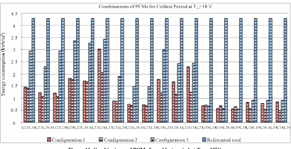
The checking of this summary needs to repeat the same study carried out for the comfort temperature at Tint = 20˚C with another comfort temperatures such for example Tint = 18˚C. Knowing that operating intervals for the hot and cold periods of the air-conditioned room at the new comfort temperature Tint= 18˚C lead to the same selection of PCMs listed above in Table 3, the results of
this further study summarized in Figure 11 shows a
minimum energy consumption for all combinations made by the PCM of Tm = 19˚C whatever the integration con-figuration in the roof.
Regarding the selected of hottest period PCM, the choice should be based on the offset of excess heat caused by the increase in temperature up to a maximum value. In this effect PCM of temperature Tm = 34˚C is most likely to be convenient for both comfort tempera- tures Tint = 18˚C and 20˚C. For other comfort tempera- tures tested, the results obtained confirm the same criteria previously mentioned.
Hence according to this remark, must be selected the most appropriate configuration for combinations con- taining suitable PCMs. Moreover the most favorable combinations of phase change materials for each config- uration will be selected according to the top yields achie- ved regardless combinations of PCMs, such as the results will be discussed in the next section.
3.5. The Most Suitable of Phase Change Materials Combinations for Each Configuration
Figure 11. Combinaisons of PCMs for coldest period at Tint = 18˚C.
Table 4. Top yields for three configurations for comfort temperatures Tint = 20˚C.
sumed is conducted for each combination relative to the referential roof calculated as:
UXLY without PCM
without PCM Annual Annual Annual 100 (11) Configuration (1) Configuration (2) Configuration (3)
Combination H21B34 H34B21 H21B34 Performance (%) −79.30 −83.44 −82.78
where:
UXLY is such X and Y are two different melting tem-peratures PCMs, while U and L means that PCMs X
and Y are respectively Upper and Lower. Table 5. Top yields for three configurations for comfort
temperatures Tint = 18˚C.
without PCM Annual
is the annual energy consumption at the
inner surface of roof without PCM. Configuration (1)
Configuration (2)
Configuration (3) Combinations H19B34 H34B19 H19B34 Performance (%) −86.82 −88.48 −87.28
UXLY
Annual
is the annual energy consumption at the inner surface of roof with PCMs of any combination of PCM X and Y.
Numerical values of this parameter, defined by Equa- tion (11), are reported respectively below in Tables 4
and 5 for comfort temperatures Tint = 20˚C and 18˚C, according to top yields for the three configurations of PCMs.
According to Tables 4 and 5, performances can reach
respectively over than (79% and 86%) in the energy economy compared to roof without PCM for three con- figurations 1, 2 and 3, respectively for comfort tempera- tures Tint=20˚C and 18˚C. For the three configurations (1, 2 and 3), the best performance is associated to the pres- ence of PCMs of Tm = 21˚C and Tm = 34˚C for comfort temperatures Tint = 20˚C, while for comfort temperatures
Tint = 18˚C the best performance is associated to the pres- ence of PCMs of Tm = 19˚C and Tm = 34˚C.
Since in configuration 1 the both PCMs are separated by concrete, always a part of energy is absorbed by con- crete layer. Then, it appears that the latent heat storage in configuration 2 and configuration 3 is more important
compared to configuration 1; therefore its performance is lower compared with other configurations. While for configurations 2 and 3, these yields can reach maximum values shown in Tables 4 and 5. In configuration 2, the
both PCMs are above of concrete; this means that the highest level of heat transfer is received by PCMs. Therefore, when the melting temperature of the upper PCM is higher than the lower PCM, the performance of the energy consumed is important
However, third configuration where both PCM are be- low of concrete, this means that the highest level of heat transfer is received by concrete layer. Thus melting tem- perature of the upper PCM is lower than the below PCM and provide the important performance of the energy consumed.
4. Conclusions
[image:9.595.307.537.459.505.2]der climate conditions of Casablanca city during all year. One roof is constituted just by conventional building materials. In the other hand, two phase change materials (PCM) are introduced in different locations within tradi- tional roof.
The parametric study produces the roof thermal be- havior was carried out using a numerical program devel- oped and successfully validated. Three multilayer roofing configurations provided with two phase change materials have been treated at different comfort temperatures; such results of two comfort temperatures 18˚C and 20˚C are detailed.
In general, combining two PCMs leads to lower annual energy consumption, when the PCM for coldest period is placed above, that is to say, close to the external envi- ronment. This is due to the fact that when it is moved down, it contributes less by a phase change as it does not undergo to external excitation.
Even the integration of PCMs in the roof is suitable, it is not always possible to have a significant reduction. Hence it is necessary to realize a study of thermal be- havior under internal and external conditions imposed.
In addition, the criteria for choosing the most suitable PCMs, according to the results obtained show that each PCM must correspond to one temperature interval (hott- est or coldest) with a choice of a PCM able to compen- sate the maximum consumption of energy imposed by the highest temperature of the hottest period, however, the other PCM suitable for the cold period should be that its melting temperature is slightly above that of comfort around +1˚C. Eventually it seems that the thermal com- fort level dictates the choice of PCM for cold period while the PCM selected for hot period should be able to compensate the highest temperature transferred to roof studied.
Finally, the three configurations lead to different re- sults, depending on the combination of PCMs. This dif- ference becomes less important when the criteria to se- lect the PCMs are respected.
REFERENCES
[1] G. Barrios, G. Huelsz and J. Rojas, “Thermal Perform- ance of Envelope Wall/Roofs of Intermittent Air-Condi- tioned Rooms,” Applied Thermal Engineering, Vol. 40, 2012, pp. 1-7.
http://dx.doi.org/10.1016/j.applthermaleng.2012.01.051 [2] A. D. Granja and L. C. Labakiny, “Influence of External
Surface Color on the Periodic Heat flow through a Flat Solid Roof with Variable Thermal Resistance,” Interna- tional Journal of Energy Research,Vol. 27, No. 8, 2003, pp. 771-779. http://dx.doi.org/10.1002/er.915
[3] M. Amir, M. Lacroix and N. Galanis, “Comportement Thermique de Dalles Chauffantes Electriques pour le Stockage Quotidien,” International Journal of Thermal Sciences,Vol. 38, No. 2, 1999, pp. 121-131.
http://dx.doi.org/10.1016/S1290-0729(99)80049-0 [4] B. Abouelkhayrat, J. Lahjomri and A. Oubarra, “Study of
Latent Accumulator Storage by Heat Transfer Fluid (HTF) and External Heat Source (EHS),” Physical and Chemical News, Vol. 66, 2012, pp. 56-68.
[5] E. M. Alawadhi, “Temperature Regulator Unit for Fluid Flow in a Channel Using Phase Change Material,” Ap- plied Thermal Engineering, Vol. 25, No. 2-3, 2005, pp. 435-449.
http://dx.doi.org/10.1016/j.applthermaleng.2004.05.018 [6] J. Kośny, K. Biswas, W. Miller and S. Kriner, “Field
Thermal Performance of Naturally Ventilated Solar Roof with PCM Heat Sink,” Solar Energy, Vol. 86, No. 9, 2012, pp. 2504-2514.
http://dx.doi.org/10.1016/j.solener.2012.05.020
[7] A. Pasupathy, L. Athanasius, R. Velraj and R. V. Seeniraj, “Experimental Investigation and Numerical Simulation Analysis on the Thermal Performance of a Building Roof Incorporating Phase Change Material (PCM) for Thermal Management,” Applied Thermal Engineering, Vol. 28, No. 5-6, 2008, pp. 556-565.
http://dx.doi.org/10.1016/j.applthermaleng.2007.04.016 [8] P. Brousseau and M. Lacroix, “Study of the Thermal
Performance of a Multi-Layer PCM Storage Unit,” En- ergy Conversion Management, Vol. 37, No. 5, 1996, pp. 599-609.http://dx.doi.org/10.1016/0196-8904(95)00207-3 [9] F. Agyenim, N. Hewitt, P. Eames and M. Smyth, “A Re-
view of Materials, Heat Transfer and Phase Change Prob- lem Formulation for Latent Heat Thermal Energy Storage Systems (LHTESS),” Renewable and SustainableEnergy Reviews,Vol. 14, No. 2, 2010, pp. 615-628.
http://dx.doi.org/10.1016/j.rser.2009.10.015
[10] P. Tatsidjodoung, N. L. Pierres and L. Luo, “A Review of Potential Materials for Thermal Energy Storage in Build- ing Applications,” Renewable and Sustainable Energy Re- views, Vol. 18, 2013, pp. 327-349.
http://dx.doi.org/10.1016/j.rser.2012.10.025
[11] A. P. Simard and M. Lacroix, “Study of the Thermal Be- havior of a Latent Heat Cold Storage Unit Operating un- der Frosting Conditions,” Energy Conversion and Man- agement, Vol. 44, No. 10, 2003, pp. 1605-1624.
http://dx.doi.org/10.1016/S0196-8904(02)00183-8 [12] K. Ouyang and F. Haghighat, “A Procedure for Calculat-
ing Thermal Response Factors of Multi-Layered Walls- State Space Method,” Building and Environment, Vol. 26, No. 2, 1991, pp. 173-177.
http://dx.doi.org/10.1016/0360-1323(91)90024-6
[13] A. K. Athienitis, “Thermal Analysis of Buildings in a Mathematical Programming Environment and Applica- tions,” Building and Environment, Vol. 34, No.4, 1999, pp. 401-415.
http://dx.doi.org/10.1016/S0360-1323(98)00031-6 [14] R. Yumrutas, M. Nsal and M. Kanoglu, “Periodic Solu-
tion of Transient Heat Flow through Multilayer Walls and Flat Roofs by Complex Finite Fourier Transform Tech- nique,” Building and Environment, Vol. 40, No. 8, 2005, pp. 1117-1125.
http://dx.doi.org/10.1016/j.buildenv.2004.09.005
Phase Change Material in Building Roof for Year Round Thermal Management,” Energy and Buildings, Vol. 40, No. 3, 2008, pp. 193-203.
http://dx.doi.org/10.1016/j.enbuild.2007.02.016
[16] F. Kuznik and J. Virgone, “Experimental Investigation of Wallboard Containing Phase Change Material: Data for Validation of Numerical Modeling,” Energy and Build- ings, Vol. 41, No. 5, 2009, pp. 561-570.
http://dx.doi.org/10.1016/j.enbuild.2008.11.022
[17] V. Alexiades and A. D. Solomon, “Mathematical Model- ing of Melting and Freezing Processes,” Hemisphere Pub- lishing Corporation, Washington DC, 1993, p. 305. [18] G. Zhou, Y. Yang and H. Xu, “Performance of Shape-
Stabilized Phase Change Material Wallboard with Peri- odical outside Heat Flux Waves,” Applied Energy, Vol. 88, No. 6, 2011, pp. 2113-2121.
http://dx.doi.org/10.1016/j.apenergy.2011.01.016
[19] Z. A. Hammou and M. Lacroix, “Anew PCM Storage System for Managing Simultaneously Solar and Electric Energy,” Energy and Building, Vol. 38, No. 3, 2006, pp. 258-265. http://dx.doi.org/10.1016/j.enbuild.2005.06.008 [20] R. Velraj, K. Anbudurai, N. Nallusamy and M. Chera-
lathan, “PCM Based Thermal Storage System for Build- ing Air Conditioning at Tidel Park, Chennai,” Proceed- ing of WREC Cologne, Germany, 2002.
[21] C. Stetiu and H. E. Feustel, “Phase Change Wallboard and Mechanical Night Ventilation in Commercial Bui- ldings,” Lawrence Berkeley National Laboratory, 1998. [22] G. Barrios and G. Huelsz, R. Rechtman and J. Rojas,
“Wall/Roof Thermal Performance Differences between Air-Conditioned and Non Air-Conditioned Rooms,” En- ergy and Building, Vol. 43, No.1, 2011, pp. 219-223. http://dx.doi.org/10.1016/j.enbuild.2010.09.015
[23] N. A. Yahaya and H. Ahmed, “Numerical Investigation of Indoor Air Temperature with the Application of PCM Gypsum Board as Ceiling Panels in Buildings,” Procedia Engineering,Vol. 20, 2011, pp. 238-248.
http://dx.doi.org/10.1016/j.proeng.2011.11.161
[24] D. Pal and Y. K. Joshi, “Thermal Management of an Avi- onics Module Using Solid-Liquid Phase-Change Materi- als,” Thermophysics and Heat Transfer, Vol. 12, No. 2, 1998, pp. 256-262.
[25] “ASHRAE Handbook of FundamentalsChapter 26,” Ame- rican Society of Heating, Refrigerating and Air-Condi- tioning Engineers (ASHRAE), New York, 1997.
[26] S. Barbaro, G. cannistraro, C. Giaconia and A. Orioli, “The Ashrae Clean Sky Model, an Evaluation in the Mediterranean Zone,” Solar and Wind Technology,Vol. 1, No. 1, 1988, pp. 111-116.