© 2016, IRJET | Impact Factor value: 4.45 | ISO 9001:2008 Certified Journal | Page 1320
MICROGRID PROTECTION USING SUPERCONDUCTING
FAULT CURRENT LIMITER
Aswathi A Nair
1, Krishna Kumari T
21
M Tech student, Dept of EEE, Adi Shankara Institute Of Engineering And Technology,Kerala,India
2
Head Of Department, Dept of EEE, Adi Shankara Institute Of Engineering And Technology,Kerala,India
---***---Abstract-
the demand for electricity is increasing rapidly and demand for power is running ahead of supply. The short-circuit capacity increases with the growth of interconnections in electrical systems . .The system parameters such as voltage and current are analysed during normal operating conditions and also during various fault conditions. The fault current limiter can be effectively used to limit the increase in over current during the fault condition. A Fault Current Limiter (FCL) is a revolutionary power grid device that limits the problems due to increase in fault current levels. It reduces prospective fault currents to a lower manageable level. The Super conducting Fault Current Limiter (SFCL) is one of the promising technologies to unravel fault current problem, because of its effective fault current limiting and quick recovery characteristic. The microgrid system with distributed generation during a three phase fault condition were simulated with and without SFCL in MATLAB/SIMULINK environment.Key Words: Fault current limiter; Over current; Microgrid ; Quick recovery; Fault ; Short-circuit capacity
1.INTRODUCTION
The Micro Grids are composed of interconnected distributed energy resources which provide continuous energy capable of supplying the internal load demand. A micro-grid is self-controlled and capable of working in grid connected mode and possesses independent control capable of controlling the micro grid on islanding mode when a grid service interruption takes place. These systems can maximize the use of renewable energy, increase the power quality and reliability level for local customers loads.[1]
The micro-grid can be classified as AC micro-grid and DC micro grid, depending upon distributed sources and loads that are connected on the basis of AC or DC power transmission. AC micro-grid has the advantage to utilize existing AC grid technologies, protections and standards, but also needs synchronization and stability for reactive power.
On the other hand, DC micro-grid has an easier control management and could eliminate DC-AC or AC-DC power electronics converters required in AC micro grid for the sources and DC loads, providing more efficiency , lower cost and system size. When there is a fault or an interruption on the AC-grid system, the DC system is disconnected from the grid, and then it is switched to the islanded operation in which the generated power is supplying the loads connected to the DC distribution system, even if one load is disconnected, it doesn't act to the stability of the micro-grid. There is only a single AC grid-side inverter needed, therefore the unit system cost and the power losses can be reduced. [9][13]
The generation sources of microgrid can include fuel cells, wind, solar, or other energy sources. The multiple dispersed generation sources and the ability to isolate the microgrid from a larger network would provide highly reliable electric power. The heat produced from these sources such as micro-turbines could be used for local process heating or space heating, allowing flexible trade of between the needs for heat and electric power.[3]
Micro grid will also be increasingly used to meet electricity needs in rural communities .The micro grid will operate in grid connected mode and also in islanded mode of operation. So the independence of operation i.e., working as islanded mode is one of the benefit of micro grid . It provides more reliability and stability over a traditional central generation. The faults and load imbalances are some of the issues related to electrical distribution systems.
© 2016, IRJET | Impact Factor value: 4.45 | ISO 9001:2008 Certified Journal | Page 1321
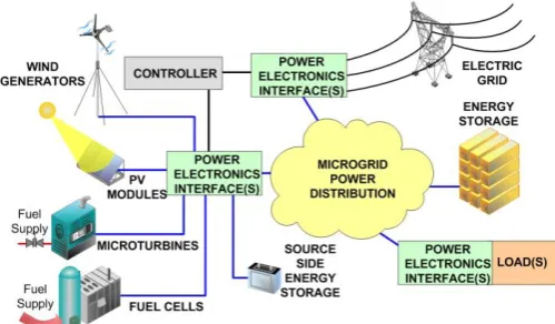
Fig -1: Block diagram of microgrid
In reality the operating conditions of micro grid are varying because of the intermittent micro-sources like wind, solar and also may be due to periodic load variation. [8]The main aim of changing network topology is to minimize loss or to achieve other economic or operational targets [4].The bi-directional power flows and low short-circuit current levels in micro grids with power electronic interfaces may use a new protection scheme, where setting parameters of relays must be updated periodically.
2. LITERATURE SURVEY
Fault currents may cause issue in grid connected and islanded mode operation of microgrid. The existing protection equipment issues like duplex power flow and amendment in voltage problem happens relying upon location of faults with regard to distributed generators.[14] The power output of distributed generators (synchronous generators, induction generators ) and inverter interfaced protection units is unpredictable due to that whenever there's a fault, power output of these DG sources changes.[13]. The increase in fault current leads to variation in fault current level, device discrimination, reduction in reach of impedance relays, duplex power flow, sympathetic tripping, islanding, single phase connection, selectivity.[10] The main significance for protecting the micro grid arises from the fact that power can flow in both the directions in each feeder of the micro grid. There may be two or more sources that contribute to the loaded power close to each local load. So in order to limit the reverse power flow fault current limiters can be used.[11]
2.1 Superconducting Fault Current Limiters
Superconducting Fault Current Limiter (SFCL) is an equipment which has the potential to scale back the fault current level inside the primary cycle of fault current .It uses the properties of superconductor to reduce the value of the
fault current. Superconductor materials lose their electrical resistance below certain critical values of temperature, magnetic field, and current density. Below these critical values it has negligible impedance and it is said to be in its superconducting mode and above these critical value it has high impedance and said to be in its current limiting mode. Increasing any of these three parameters above their critical value causes the material to quench i.e. switch from its
superconducting mode to its high resistance mode. Superconducting fault current utilizes variable
impedance which is connected in series with the electrical system that varies depending on operating conditions. When faults occur, the impedance rises to a value where fault current is correspondingly reduced to a lower level which the circuit breaker can handle .[17]
Super-conductors are of two types-
• Low temperature superconductors. • High temperature superconductors.
Low temperature superconductors(LTS) are first generation superconductors and these classical metallic superconductors have transition temperatures below 25 K. Due to the low operating temperature (usually the material is cooled using liquid helium to 4.2 K),the cooling costs are extremely high and fault current limiters based on LTS are not expected to be commercialized. The major advantages of this material is its inexpensiveness, hence utilizing .MgB2 is expected to reduce the cost for superconducting material used in the SCFCL. Superconducting fault current limiter (SFCL) is an ideal current limiter, but it is still only in the researching stage.
Superconducting fault current limiters are basically of two types:
• Resistive type SFCL • Inductive type SFCL
2.1.1 Resistive type SFCL
In the resistive type ,the superconducting element connected in series with the network. It is the simplest type of SFCL. It can be just only a low temperature superconducting wire or a certain length of high temperature superconductors. The superconductor will be in superconducting state without resistance when the current is normal. When the current exceeds over the critical current, the superconductor goes into its normal state .It has a high resistance which is connected in series with the network that will limit the current.[19]
© 2016, IRJET | Impact Factor value: 4.45 | ISO 9001:2008 Certified Journal | Page 1322
Fig-2: Schematic of Resistive Fault Current Limiter.
2.1.2 Inductive type SFCL
In this type of fault current limiter a special transformer connected in series with the network that has a conventional primary coil and secondary coil: a superconductor ring.The superconductor ring gives a de-excitation when the current is normal. The primary winding acting as the main current lead of the circuit is built in a way not to be exposed to the cryogenic part but to the temperature level of the environment. During the normal operation the magnetic field gets expelled from the superconductor. That means that the magnetic flux, generated by the primary winding, is not able to penetrate the iron core.
The iron core doesn't cause any magnetization losses and the limiter inserts very low impedance to the network. Only in the resistive state when the superconductor is no longer able to expel the magnetic field, large impedance is inserted into the network. Secondary winding blocks the magnetic flux in the iron core. In case of a failure current the dissipated current into the secondary winding becomes much high that the superconducting state will be broken. The voltage induced in the secondary by-pass winding by coupling of the iron core will cause the counter induction to reduce the current in the primary coil.[16]
The secondary winding is divided into two parts, the super conductive winding and its normal conductive bypass. As the superconductor is based on an YBCO ceramic, changing from super conductive to normal state would dissipate so much energy into the ceramic material that it would be destroyed. Therefore a bypass coil is taking over the current owing in the normal state.
Fig-3: Schematic of Inductive Fault Current Limiter.
2.2 Modelling of Superconducting Fault Current
Limiters
The mathematical model for a resistive SFCL applied in the actual power distribution system , can be expressed as:
(1)
Where Rn and τ represent the impedance being saturated at normal temperature and time constant respectively. In addition,t0, t1, and t2 represent quench-starting time, the first recovery quench-starting time, and the secondary recovery-starting time, respectively .. As shown in Fig.3, it indicates the detailed quenching and recovery characteristics.
© 2016, IRJET | Impact Factor value: 4.45 | ISO 9001:2008 Certified Journal | Page 1323 The features of the identified fault current limiter are as
follows:
Rapid Response
No external control is needed.
Negligible loss during normal system operation.
3. MATLAB/SIMULINK MODEL
The simulation of the Superconducting fault current limiter has been carried out by MATLAB software and the simulation models are shown. .A 3 phase inverter is used to convert the input DC to AC. The PQ control is implemented for the grid connected mode.
Fig- 5: Simulation circuit of microgrid system without SFCL
Fig.4. shows the simulation circuit of the microgrid system without SFCL .The input voltage given to the battery source is 800 V . The active and reactive power is made to be constant. The DG system was designed to supply 10KW active power and zero reactive power.Load is connected at the microgrid side .The remaining required power for the load is fed by the main grid.
Fig- 6: Simulation circuit of microgrid system with SFCL
Fig.5. shows the simulation circuit of the the microgrid system with SFCL. The SFCL is being placed at tht PCC where the microgrid is connected to the main grid.A three phase fault is induced in the PCC to analyse the performance of SFCL.A load is connected at the microgrid side.
4. SIMULATION RESULTS
4.1 Simulated grid voltage and current waveform of
mic
rogrid system without SFCL
Fig-7: Output waveforms of grid voltage and current waveform of microgrid system without SFCL
© 2016, IRJET | Impact Factor value: 4.45 | ISO 9001:2008 Certified Journal | Page 1324
3.2 Simulated Output grid voltage and current
waveform of microgrid system with SFCL
Fig- 8: Output grid voltage and current waveform of microgrid system with SFCL.
Fig.8 shows the grid output voltage and current waveform of microgrid system with SFCL.During grid connected mode three phase fault condition is induced at PCC, the fault transition period is between 0.4sec - 0.5sec.
4. CONCLUSION
Microgrid is one of the solutions to energy crisis. It's primarily network comprising of distributed generation sources, storage system and governable hundreds, which might operate in grid connected mode or just in case of fault in isolated mode. Protection system should isolate the microgrid from the main grid so as to protect the microgrid. The fast operation of protection improves the ability to maintain synchronism after transition to islanded operation, which is crucial from view point of stability [4]
FCL's provide the opportunity to increase distribution and transmission equipment utilization and reduce reinforcement requirements. SFCL technologies continue to make progress toward commercialization as power utilities worldwide deal with the issue of increasing fault current levels due to the integration of distributed energy resources.
The microgrid system with distributed generation during a three phase fault condition was simulated with and without SFCL in MATLAB/SIMULINK environment. From the results, applying the resistive SFCL can effectively limit and rapidly quench the fault current during three phase fault current and guarantee the power balance, and improve the micro-grid system’s voltage and frequency stability.
5. REFERENCES
[1] Hartono B.S, Budiyanto Y,Setiabudy R. Review of microgrid technologyIEEE International Conference on QiR (Quality in Research), June 2013, Page(s):127 132
[2] Marnay C, Venkataramanan G, "Microgrids in the evolving electricity generation and delivery infrastructure," Power Engineering Society General Meeting, 2006.
[3] Eto J,Lasseter R ,Schenkman B , Stevens J ,Klapp D ,Volkommer H ,Linton E ,Hur-tado H ,Roy J , "Overview of the CERTS Microgrid laboratory Test Bed,"Integration of Wide-Scale Renewable Resources Into the Power Delivery System, 2009 CIGRE/IEEE PES Joint Symposium , vol no., pp.1, 29-31 July 2009
[4] Vandoorn, Meersman B. Analogy Between Conventional Grid Control and Islanded Microgrid Control Based on a Global DC-LinkVoltage DroopIEEE Transactions onPower Delivery, Volume: 27 , Issue: 3 ,July 2012 , pp1405 1414
[5] Etemadi, A.H. "Overcurrent and Overload Protection of Directly Voltage-Controlled Distributed Resources in a Microgrid” IEEE Transactions on Industrial Electronics, Volume:60, Issue: 12 ) Dec. 2013 Pp:5629 - 5638
[6] Kasem Alaboudy A.H, Kirtley J.L. "Microgrid Stability Characterization Subsequent to Fault Triggered Islanding Incidents, IEEE Transactions on Power Delivery, Volume:27 , Issue: 2 ,April 2012 pp:658 669
[7] S. Chowdhury, S. Chowdhury, and P. Crossley, "Microgrids and active distribution networks".Institution of Engineering and Technology, 2009
[8] D. Wei T, Xisheng, and Q. Zhiping, Research on dynamic stability of hybrid wind/pv system based on micro-grid, Electrical Machines and systems,2008. ICEMS 2008. International Conference on, pp. 2627263.
© 2016, IRJET | Impact Factor value: 4.45 | ISO 9001:2008 Certified Journal | Page 1325 [10] J.Driesen, P. Vermeyen, and R. Belmans, “Protection
issues in microgrid with multiple distribution generation units,” in Proc.of Power Conversion Conference,Nagoya, pp. 646- 653,October 2010.
[11]Teymoor Ghanbari; Student, IEEE, “Unidirectional Fault Current Limiter:An Efficient Interface Between the Microgrid and Main network,”IEEE Transactions On Power Delivery, Vol. 28, No. 2, May 2013
[12]B.Hussain, S.Sharkh, Hussain, and
M.Abusara,"Integration of distributed generation into the grid: protection challenges and solutions," 10th IET International Conference on Developments in Power System Protection, pp. 1-5, March/April 2010
[13] Bahramirad, S. Khodaei, A. Reliability-Constrained Optimal Sizing of Energy Storage System in a Microgrid IEEE Transactions on Smart Grid, Volume:3 , Issue: 4 Dec. 2012 pp:2056 2062
[14] ] S. Conti, “Protection issues and state of art microgrids with inverter interfaced distributed generators,” International Conference on Clean electrical power, pp. 643-647, June 2011.
[15] Kasem Alaboudy, A.H.Kirtley, J.L." Microgrid Stability Characterization Subsequent to Fault Triggered Islanding Incidents , IEEE Transactions on Power Delivery
, Volume:27 , Issue: 2 ,April 2012 pp:658 669
[16] S.Ustun, C.Ozansoy,and A.Zaygeth, “A centralised microgrid protection System for network with fault current limiters,”10th International Conference on Environment and ElectricalEngineering, 2011
[17] B. Sung., D. Park., T. Ko. “Study on optimal location of a resistive SFCL applied to an electric power grid”. IEEE Trans. On applied supercond. vol.13, no. 2, June 2003.
[18]V.Sokolovsky.,V. Meerovich., I. Vajda.” Superconducting FCL: Design and Application”, IEEE Trans. On applied Supercond. vol.14, no.3, Sept. 2004.
[19] Y. Cai, S. Okuda, T. Odake, T. Yagai, M. Tsuda, and T. Hamajima, “Study on three-phase superconducting fault currentlimiter,”IEEETrans.Appl.Supercond.,vol.20,no.pp.3,11 27–1130, Jun. 2010.
[20] Divya. S, Krishnakumari. T., “Combination of Super-Capacitor-Switch type fault current limiter for LVRT enhancement of DFIG wind turbines, “International Conference on Control, Communication &Computing India(ICCC).,19–21, November. 2015.
Ms. Aswathi A Nair, M.Tech Student, Dept of EEE. Adi Shankara Institute Of Engineering And Technology. Received B.Tech in Electrical And Electronics Engineering from Anna University, Chennai. Areas of interests are Power Electronics and Power System.