Table of Contents
HART APPLICATION GUIDE
Preface... 1
Theory of Operation... 2
Communication Modes ... 3
Master-Slave Mode ... 3
Burst Mode... 3
Frequency Shift Keying ... 4
HART Networks ... 5 Point-to-Point ... 5 Multidrop ... 6 HART Commands ... 7 Universal... 7 Common Practice ... 7 Device Specific... 7 Summary Table ... 7
Establishing Communication with a HART Device... 8
Device Description ... 8
Benefits of HART Communication ... 9
Improved Plant Operations... 10
Cost Savings in Commissioning ... 10
Cost Savings in Installation ... 10
Improved Measurement Quality ... 11
Cost Savings in Maintenance... 12
Operational Flexibility ... 13
Instrumentation Investment Protection ... 14
Compatibility of HART Revisions ... 14
Digital Communication ... 15
Getting the Most out of HART Systems ... 16
Wiring and Installation... 17
Cable Length... 17
Intrinsic Safety ... 18
Intrinsic Safety Devices ... 18
Designing an IS System Using Shunt-Diode Barriers ... 19
Designing an IS System Using Isolators... 20
Multidrop IS Networks... 21
IS Output Loops ... 21
IS Certification Considerations ... 21
IS Network Cable Length Calculations ... 21
HART Multidrop Networks ... 22
Multidrop with HART Field Controllers ... 23
Application Considerations ... 23
Table of Contents
HART APPLICATION GUIDEData Handling ... 25
Passthrough Feature... 25
Gateways... 25
SCADA/RTU Systems... 25
Multiplexers... 26
Multiplexer as the Primary I/O System... 26
Parallel Monitoring with a Multiplexer... 26
Reading HART Data into NonHART Systems ... 28
HART Data-Conversion Products ... 28
Universal Handheld Communicator ... 30
PC Configuration Software ... 31
Summary Table of HART Software ... 31
Commissioning HART Networks ... 32
Device Verification ... 32
Loop Integrity Check ... 32
As-Installed Record Keeping ... 32
Device Status and Diagnostics... 33
Connecting a PC to a HART Device or Network... 34
PC Application Development Tools... 35
Control in Field Devices ... 36
HART Field Controller Implementation ... 37
Industry Applications ... 38
Inventory-Management Applications ... 39
HART Multidrop Network for Tank Level and Inventory Management ... 39
Multidrop for Tank Farm Monitoring ... 40
Underground Petroleum Storage with HART Communication for Accuracy ... 41
Cost-Saving Applications ... 42
Wastewater Treatment Plant Upgrade ... 42
Appliance Manufacturing with Multidrop ... 43
Remote Rezeroing in a Brewery... 44
Water Treatment Facility Upgrade... 45
Improved Diagnostics ... 46
Remote-Operation Applications... 47
Unmanned Offshore Gas Production with HART Networks ... 47
Venezuela Gas-Lift Project ... 48
Open-Architecture Applications ... 49
Oil Refinery Expansion ... 49
HART Within a PROFIBUS Network ... 50
Table of Contents
HART APPLICATION GUIDE
Where to Find Information ... 52
By Mail ... 52
By Phone ... 52
By Fax ... 52
By E-mail... 52
Online ... 52
Appendix A: HART Checklist ... 53
HART Host System Capabilities Checklist ... 53
Appendix B: HART Revision 5... 56
Universal Commands in HART Revision 5... 56
Appendix C: HART Revisions 2, 3, and 4... 58
Universal Commands in HART Revisions 2, 3, and 4 (Differences from Revision 5)... 58
These commands did not exist before Revision 5.0. ... 59
Appendix D: Common Practice Commands ... 60
Common Practice Commands ... 60
Appendix E: Response Codes ... 65
Status ... 65
Response Codes ... 65
First Byte ... 65
Second Byte ... 66
Appendix F: HART Field Control ... 67
HART Field Controller Installation ... 67
Appendix G: Technical Information ... 69
Communication Signals ... 69
Data Information ... 69
Simple Command Structure ... 69
Communication Masters ... 69 Variables... 69 Wiring Topologies ... 69 Cable Lengths ... 69 Intrinsically Safe... 69 Glossary ... 71
Preface
In today’s competitive environment, all companies seek to reduce operation costs, deliver products rapidly, and improve product quality. The HART®
(highway addressable remote transducer) protocol directly contributes to these business goals by providing cost savings in:
q Commissioning and installation q Plant operations and improved quality q Maintenance
The HART Application Guide has been created by the HART
Communication Foundation (HCF) to provide users of HART products with the information necessary to obtain the full benefits of HART digital instrumentation. The HART communication protocol is an open standard owned by the more than 100 member companies in the HCF. Products that use the HART protocol to provide both analog 4–20 mA and digital signals provide flexibility not available with any other communication technology. The following four sections provide you with an understanding of how the HART technology works, insight on how to apply various features of the technology, and specific examples of applications implemented by HART protocol users around the world:
q Theory of Operation
q Benefits of HART Communication q Getting the Most from HART Systems q Industry Applications
Theory of Operation
The following sections explain the basic principles behind the operation of HART instruments and networks:
q Communication Modes q Frequency Shift Keying q HART Networks q HART Commands THEORYOF OPERATION
Communication Modes
M
ASTER-S
LAVEM
ODEHART is a master-slave communication protocol, which means that during normal operation, each slave (field device) communication is initiated by a
master communication device. Two masters can connect to each HART loop. The primary master is generally a distributed control system (DCS), programmable logic controller (PLC), or a personal computer (PC). The secondary master can be a handheld terminal or another PC. Slave devices include transmitters, actuators, and controllers that respond to commands from the primary or secondary master.
B
URSTM
ODE Some HART devices support the optional burst communication mode. Burst mode enables faster communication (3–4 data updates per second). In burst mode, the master instructs the slave device to continuously broadcast a standard HART reply message (e.g., the value of the process variable). The master receives the message at the higher rate until it instructs the slave to stop bursting.Use burst mode to enable more than one passive HART device to listen to communications on the HART loop.
Frequency Shift Keying
The HART communication protocol is based on the Bell 202 telephone communication standard and operates using the frequency shift keying
(FSK) principle. The digital signal is made up of two frequencies— 1,200 Hz and 2,200 Hz representing bits 1 and 0, respectively. Sine waves of these two frequencies are superimposed on the direct current (dc) analog signal cables to provide simultaneous analog and digital communications (Figure 1). Because the average value of the FSK signal is always zero, the 4–20 mA analog signal is not affected. The digital communication signal has a response time of approximately 2–3 data updates per second without interrupting the analog signal. A minimum loop impedance of 230 Ω is required for communication.
Figure 1: Simultaneous Analog and Digital Communication “1” “0” “1” “1” “1” “1” “0” “0” “0” Time 20 mA 4 mA Digital Signal Analog Signal
Note: Drawing not to scale.
HART Networks
HART devices can operate in one of two network configurations—point-to- point or multidrop.
P
OINT-
TO-P
OINT In point-to-point mode, the traditional 4–20 mA signal is used to communicate one process variable, while additional process variables, configuration parameters, and other device data are transferred digitally using the HART protocol (Figure 2). The 4–20 mA analog signal is not affected by the HART signal and can be used for control in the normal way. The HART communication digital signal gives access to secondary variables and other data that can be used for operations, commissioning, maintenance, and diagnostic purposes.Figure 2: Point-to-Point Mode of Operation
Control System or Other Host Application Multiplexer Barrier Handheld Terminal Field Device
Note: Instrument power is provided by an interface or external power source that is not shown.
HART Networks
M
ULTIDROP The multidrop mode of operation requires only a single pair of wires and, if applicable, safety barriers and an auxiliary power supply for up to 15 field devices (Figure 3). All process values are transmitted digitally. Inmultidrop mode, all field device polling addresses are >0, and the current through each device is fixed to a minimum value (typically 4 mA).
Figure 3: Multidrop Mode of Operation
Use multidrop connection for supervisory control installations that are widely spaced, such as pipelines, custody transfer stations, and tank farms.
Input/Output (I/O) System
Handheld Terminal
Field Devices Control System or Other Host Application
Note: Instrument power is provided by an interface or external power source that is not shown.
HART Commands
The HART command set provides uniform and consistent communication for all field devices. The command set includes three classes: universal,
common practice, and device specific (Table 1). Host applications may
implement any of the necessary commands for a particular application.
U
NIVERSAL All devices using the HART protocol must recognize and support theuniversal commands. Universal commands provide access to information useful in normal operations (e.g., read primary variable and units).
C
OMMONP
RACTICECommon practice commands provide functions implemented by many, but not necessarily all, HART communication devices.
D
EVICES
PECIFIC Device-specific commands represent functions that are unique to each field device. These commands access setup and calibration information, as well as information about the construction of the device. Information on device-specific commands is available from device manufacturers.S
UMMARYT
ABLEUniversal Commands Common Practice Commands Device-Specific Commands
• Read manufacturer and device type
• Read primary variable (PV) and units
• Read current output and percent of range
• Read up to four predefined dynamic variables
• Read or write eight-character tag, 16-character descriptor, date
• Read or write 32-character message
• Read device range values, units, and damping time constant
• Read or write final assembly number
• Read selection of up to four dynamic variables
• Write damping time constant • Write device range values • Calibrate (set zero, set span) • Set fixed output current • Perform self-test • Perform master reset • Trim PV zero • Write PV unit
• Trim DAC zero and gain • Write transfer function (square
root/linear)
• Write sensor serial number • Read or write dynamic variable
assignments
• Read or write low-flow cut-off • Start, stop, or clear totalizer • Read or write density calibration
factor
• Choose PV (mass, flow, or density)
• Read or write materials or construction information • Trim sensor calibration • PID enable
• Write PID setpoint • Valve characterization • Valve setpoint • Travel limits • User units
• Local display information
HART Commands
E
STABLISHINGC
OMMUNICATION WITHAHART D
EVICEEach HART device has a 38-bit address that consists of the manufacturer ID code, device type code, and device-unique identifier. A unique address is encoded in each device at the time of manufacture. A HART master must know the address of a field device in order to communicate successfully with it. A master can learn the address of a slave device by issuing one of two commands that cause the slave device to respond with its address:
q Command 0, Read Unique Identifier—Command 0 is the preferred
method for initiating communication with a slave device because it enables a master to learn the address of each slave device without user interaction. Each polling address (0–15) is probed to learn the unique address for each device.
q Command 11, Read Unique Identifier by Tag - Command 11 is useful
if there are more than 15 devices in the network or if the network devices were not configured with unique polling addresses.
(Multidropping more than 15 devices is possible when the devices are individually powered and isolated.) Command 11 requires the user to specify the tag numbers to be polled.
D
EVICED
ESCRIPTIONSome HART host applications use device descriptions (DD) to obtain information about the variables and functions contained in a HART field device. The DD includes all of the information needed by a host application to fully communicate with the field device. HART Device Description Language (DDL) is used to write the DD, that combines all of the
information needed by the host application into a single structured file. The DD identifies which common practice commands are supported as well as the format and structure of all device-specific commands.
ADD for a HART field device is roughly equivalent to a printer driver for a computer. DDs eliminate the need for host suppliers to develop and support custom interfaces and drivers. A DD provides a picture of all parameters and functions of a device in a standardized language. HART suppliers have the option of supplying a DD for their HART field product. If they choose to supply one, the DD will provide information for a DD-enabled host application to read and write data according to each device’s procedures. DD source files for HART devices resemble files written in the C
programming language. DD files are submitted to the HCF for registration in the HCF DD Library. Quality checks are performed on each DD
submitted to ensure specification compliance, to verify that there are no conflicts with DDs already registered, and to verify operation with standard HART hosts. The HCF DD Library is the central location for management
Benefits of HART Communication
The HART protocol is a powerful communication technology used to exploit the full potential of digital field devices. Preserving the traditional 4–20 mA signal, the HART protocol extends system capabilities for two-way digital communication with smart field instruments. The HART protocol offers the best solution for smart field device communications and has the widest base of support of any field device protocol worldwide. More instruments are available with the HART protocol than any other digital communications technology. Almost any process application can be addressed by one of the products offered by HART instrument suppliers.
Unlike other digital communication technologies, the HART protocol provides a unique communication solution that is backward compatible with the installed base of instrumentation in use today. This backward compatibility ensures that investments in existing cabling and current control strategies will remain secure well into the future.
Benefits outlined in this section include:
q Improved plant operations q Operational flexibility
q Instrumentation investment protection q Digital communication
Improved Plant Operations
The HART protocol improves plant performance and provide savings in:
q Commissioning and installation q Plant operations and improved quality q Maintenance
C
OSTS
AVINGSINC
OMMISSIONINGHART-based field devices can be installed and commissioned in a fraction of the time required for a traditional analog-only system. Operators who use HART digital communications can easily identify a field device by its tag and verify that operational parameters are correct. Configurations of similar devices can be copied to streamline the commissioning process. A loop integrity check is readily accomplished by commanding the field transmitter to set the analog output to a preset value.
C
OSTS
AVINGSINI
NSTALLATIONThe HART protocol supports the networking of several devices on a single twisted wire pair. This configuration can provide significant savings in wiring, especially for applications such as tank monitoring.
Multivariable devices reduce the number of instruments, wiring, spare parts, and terminations required. Some HART field instruments embed PID control, which eliminates the need for a separate controller, and results in significant wiring and equipment cost savings.
Use HART multidrop mode to connect multiple instruments to a single cable and reduce installation costs.
Improved Plant Operations
I
MPROVEDM
EASUREMENTQ
UALITYHART-communicating devices provide accurate information that helps improve the efficiency of plant operations. During normal operation, device operational values can be easily monitored or modified remotely. If uploaded to a software application, these data can be used to automate record keeping for regulatory compliance (e.g., environmental, validation, ISO9000, and safety standards).
Numerous device parameters are available from HART-compatible instruments that can be communicated to the control room and used for control, maintenance, and record keeping (Figure 4).
Figure 4: Examples of Device Parameters Sent to Control Room
Some HART devices perform complex calculations, such as PID control algorithms or compensated flow rate. Multivariable HART-capable instruments take measurements and perform calculations at the source, which eliminates time bias and results in more accurate calculations than are possible when performed in a centralized host.
Some HART field devices store historical information in the form of trend logs and summary data. These logs and statistical calculations (e.g., high
The HART protocol provides access to all information in multivariable devices. In addition to the analog output (primary variable), the HART protocol provides access to all measurement data that can be used for verification or
calculation of plant mass and energy balances.
Control Room Field
Device
BENEFITSOF HART COMMUNICATION
Tag Message Descriptor Range Values Diagnostic Information Four Process Variables
Construction Materials 128 Device Variables
Serial Numbers Damping
Improved Plant Operations
C
OSTS
AVINGSINM
AINTENANCEThe diagnostic capabilities of HART-communicating field devices can eliminate substantial costs by reducing downtime. The HART protocol communicates diagnostic information to the control room, which
minimizes the time required to identify the source of any problem and take corrective action. Trips into the field or hazardous areas are eliminated or reduced.
When a replacement device is put into service, HART communication allows the correct operational parameters and settings to be quickly and accurately uploaded into the device from a central database. Efficient and rapid uploading reduces the time that the device is out of service. Some software applications provide a historical record of configuration and operational status for each instrument. This information can be used for predictive, preventive, and proactive maintenance.
Operational Flexibility
The HART protocol allows two masters (primary and secondary) to communicate with slave devices and provide additional operational flexibility. A permanently connected host system can be used simultaneously, while a handheld terminal or PC controller is communicating with a field device (Figure 5).
Figure 5: Multimaster System
The HART protocol ensures interoperablility among devices through universal commands that enable hosts to easily access and communicate the most common parameters used in field devices. The HART DDL extends interoperability to include information that may be specific to a particular device. DDL enables a single handheld configurator or PC host application to configure and maintain HART-communicating devices from any manufacturer. The use of common tools for products of different vendors minimizes the amount of equipment and training needed to maintain a plant.
HART extends the capability of field devices beyond the single-variable limitations of 4-20mA in hosts with HART capability.
Transmitter Secondary Master Primary Master: Control System or Other Host Application Analog Digital Data (2–3 updates per second) HART Interface Power Supply
Instrumentation Investment Protection
Existing plants and processes have considerable investments in wiring, analog controllers, junction boxes, barriers, marshalling panels, and analog or smart instrumentation. The people, procedures, and equipment already exist for the support and maintenance of the installed equipment. HART field instruments protect this investment by providing compatible products with enhanced digital capabilities. These enhanced capabilities can be used incrementally.
At the basic level, HART devices communicate with a handheld terminal for setup and maintenance. As needs grow, more sophisticated, on-line, PC-based systems can provide continuous monitoring of device status and configuration parameters. Advanced installations can also use control systems with HART I/O capability. The status information can be used directly by control schemes to trigger remedial actions and allow on-line reranging based on operating conditions and direct reading of multivariable instrument data.
C
OMPATIBILITYOFHART R
EVISIONSAs HART field devices are upgraded, new functions may be added. A basic premise of the HART Protocol is that new HART instruments must behave in precisely the same manner as older versions when interfaced with an earlier revision host system.
The HART communication protocol enables you to retain your previous investments in existing hardware and personnel.
Digital Communication
A digital instrument that uses a microprocessor provides many benefits. These benefits are found in all smart devices regardless of the type of communication used. A digital device provides advantages such as improved accuracy and stability. The HART protocol enhances the capabilities of digital instruments by providing communication access and networking (Table 2).
Table 2: Digital Instruments Versus HART Instruments
Benefits HART Instruments Digital Instruments
Accuracy and stability Reliability
Multivariable Computations Diagnostics
Multiple sensor inputs Ease of commissioning Tag ID
Remote configuration Loop checks
Adjustable operational parameters Access to historical data
Multidrop networking
Access by multiple host devices Extended communication distances Field-based control Interoperability ✓ ✓ ✓ ✓ ✓ ✓ ✓ ✓ ✓ ✓ ✓ ✓ ✓ ✓ ✓ ✓ ✓ ✓ ✓ ✓ ✓ ✓ ✓
Getting the Most out of HART Systems
To take full advantage of the benefits offered by the HART communication protocol, it is important that you install and implement the system correctly. The following sections contain information that can help you to get the most from your HART system:
q Wiring and Installation q Intrinsic safety
q HART multidrop networks q Control system interfaces q Multiplexers
q Reading HART data into nonHART systems q Universal handheld communicator
q PC configuration software q Commissioning HART networks q Device status and diagnostics
q Connecting a PC to a HART device or network q PC application development tools
q Control in field devices GETTINGTHE MOST FROM HART SYSTEMS
Wiring and Installation
In general, the installation practice for HART communicating devices is the same as conventional 4-20mA instrumentation. Individually shielded twisted pair cable, either in single-pair or multi-pair varieties, is the recommended wiring practice. Unshielded cables may be used for short distances if ambient noise and cross-talk will not affect communication. The minimum conductor size is 0.51 mm diameter (#24 AWG) for cable runs less than 1,524 m (5,000 ft) and 0.81 mm diameter (#20 AWG) for longer distances.
C
ABLEL
ENGTH Most installations are well within the 3,000 meter (10,000 ft) theoretical limit for HART communication. However, the electrical characteristics of the cable (mostly capacitance) and the combination of connected devices can affect the maximum allowable cable length of a HART network. Table 3 shows the affect of cable capacitance and the number of network devices on cable length. The table is based on typical installations of HART devices in non-IS environments, i.e. no miscellaneous series impedance. Detailed information for determining the maximum cable length for any HART network configuration can be found in the HART Physical Layer Specifications.Cable Capacitance – pf/ft (pf/m) Cable Length – feet (meters) No. Network Devices 20 pf/ft (65 pf/m) 30 pf/ft (95 pf/m) 50 pf/ft (160 pf/m) 70 pf/ft (225 pf/m) 1 9,000 ft (2,769 m) 6,500 ft (2,000 m) 4,200 ft (1,292 m) 3,200 ft (985 m) 5 8,000 ft (2,462 m) 5,900 ft (1,815 m) 3,700 ft (1,138 m) 2,900 ft (892 m) 10 7,000 ft (2,154 m) 5,200 ft (1,600 m) 3,300 ft (1,015 m) 2,500 ft (769 m) 15 6,000 ft (1,846 m) 4,600 ft (1,415 m) 2,900 ft (892 m) 2,300 ft (708 m) Table 3: Allowable cable lengths for 1.02 mm (#18 AWG)
shield twisted pair
Intrinsic Safety
Intrinsic safety (IS) is a method of providing safe operation of electronic process-control instrumentation in hazardous areas. IS systems keep the available electrical energy in the system low enough that ignition of the hazardous atmosphere cannot occur. No single field device or wiring is intrinsically safe by itself (except for battery-operated, self-contained devices), but is intrinsically safe only when employed in a properly designed IS system.
I
NTRINSICS
AFETYD
EVICESHART-communicating devices work well in applications that require IS operation. IS devices (e.g., barriers) are often used with traditional
two-wire 4–20 mA instruments to ensure an IS system in hazardous areas. With traditional analog instrumentation, energy to the field can be limited with or without a ground connection by installing one of the following IS devices:
q Shunt-diode (zener) barriers that use a high-quality safety ground
connection to bypass excess energy (Figure 6)
q Isolators, which do not require a ground connection, that repeat the
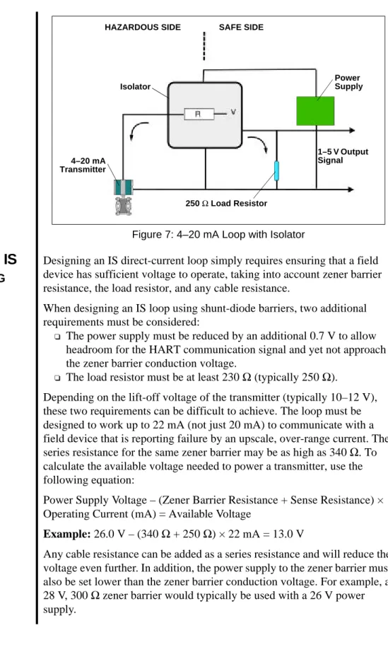
analog measurement signal across an isolated interface in the safe-side load circuit (Figure 7 on page 19)
Both zener barriers and isolators can be used to ensure an IS system with HART-communicating devices, but some additional issues must be considered when engineering the HART loop.
Figure 6: 4–20 mA Loop with a Zener Barrier
Power Supply
250 Ω Load Resistor Transmitter
Zener Barrier
HAZARDOUS SIDE SAFE SIDE
1–5 V Output Signal GETTINGTHE MOST FROM HART SYSTEMS
Intrinsic Safety
Figure 7: 4–20 mA Loop with Isolator
D
ESIGNINGANIS
S
YSTEMU
SINGS
HUNT-D
IODEB
ARRIERSDesigning an IS direct-current loop simply requires ensuring that a field device has sufficient voltage to operate, taking into account zener barrier resistance, the load resistor, and any cable resistance.
When designing an IS loop using shunt-diode barriers, two additional requirements must be considered:
q The power supply must be reduced by an additional 0.7 V to allow
headroom for the HART communication signal and yet not approach the zener barrier conduction voltage.
q The load resistor must be at least 230 Ω (typically 250 Ω).
Depending on the lift-off voltage of the transmitter (typically 10–12 V), these two requirements can be difficult to achieve. The loop must be designed to work up to 22 mA (not just 20 mA) to communicate with a field device that is reporting failure by an upscale, over-range current. The series resistance for the same zener barrier may be as high as 340 Ω. To calculate the available voltage needed to power a transmitter, use the following equation:
Power Supply Voltage – (Zener Barrier Resistance + Sense Resistance) × Operating Current (mA) = Available Voltage
Example: 26.0 V – (340 Ω + 250 Ω) × 22 mA = 13.0 V Power Supply SAFE SIDE HAZARDOUS SIDE 4–20 mA Transmitter 250 Ω Load Resistor Isolator 1–5 V Output Signal GETTINGTHE MOST FROM HART SYSTEMS
Intrinsic Safety
While it is difficult to meet the two requirements noted above for a network using shunt-diode barriers, it can be done. Following are two possible solutions to the problem:
1. Shunt the load resistor with a large inductor so that the load resistor impedance is still high (and mainly resistive) at HART signal frequencies, but much lower at direct current. This solution, while it does work, is physically somewhat inconvenient.
2. Use an IS isolator rather than a shunt-diode barrier. The output voltage on the hazardous side is usually specified as greater than X Vdc at
20 mA (typically 14–17 V). This value already includes the voltage
drop due to the internal safety resistor, so the only extra voltage drop is that due to cable resistance. System operation at 22 mA requires reducing the 20 mA voltage by 0.7 V (340 Ω × 2 mA).
D
ESIGNINGANIS
S
YSTEMU
SINGI
SOLATORSThe implementation of HART loops in an IS system with isolators requires more planning. An isolator is designed to recreate the 4–20 mA signal from the field device in the safe-side load circuit. Most older isolator designs will not carry the high frequencies of HART current signals across to the safe side, nor will they convey HART voltage signals from the safe side to the field. For this reason, HART communication through the isolator is not possible with these older designs. (It is still possible to work with a handheld communicator or PC with an IS modem on the hazardous side of the isolator.) When retrofitting HART instruments into an existing
installation, inspect the system for isolators that may have to be replaced (any isolators that will not support HART signals).
IS device suppliers can assist with certification and performance specifications for their HART-compatible products. Field device manufacturers will also supply certification details for their specific products.
Major suppliers of IS isolators have introduced designs that are fully HART compatible. Modern IS isolators provide trouble-free design and operation and transparent communication in both directions.
Intrinsic Safety
M
ULTIDROPIS
N
ETWORKSHART multidrop networks are particularly suitable for intrinsically safe installations. With a multidrop configuration, fewer barriers or isolators are required. In addition, because each field device takes only 4 mA (for a total of 16 mA in a four-device loop), plain zener barriers can be used. With a 250 Ω load, 25 V – (340 + 250 Ω) × 16 mA = 15.5 V, which is well above the transmitter lift-off voltage and leaves a margin for cable resistance.
IS O
UTPUTL
OOPS For output devices such as valve positioners, direct-current voltageconsiderations will vary depending on the drive requirements of the device. Zener barriers may be possible. If not, modern HART-compatible output isolators are appropriate.
IS C
ERTIFICATIONC
ONSIDERATIONSIf the HART loop contains an IS-approved handheld communicator or modem, slight changes may be needed to meet IS installation certification rules. Handheld communicators and modems add the HART signal voltage to the voltage level coming from the zener barrier or isolator. For example, a handheld communicator typically adds a maximum of 2 V to the loop. Therefore, when used with a 28 V zener barrier, a total of 30 V may theoretically be present in the loop. The allowable capacitance must be reduced by about 15% to account for this increase in voltage.
IS N
ETWORKC
ABLEL
ENGTHC
ALCULATIONSThe cable length calculation must include the resistance of both the zener barrier and the load resistor.
HART Multidrop Networks
The HART communication protocol enables several instruments to be connected on the same pair of wires in a multidropnetwork configuration (Figure 8). The current through each field device is fixed at a minimum value (typically 4 mA) sufficient for device operation. The analog loop current does not change in relation to the process and thus does not reflect the primary variable. Communications in multidrop mode are entirely digital.
Figure 8: Multidrop Configuration
Standard HART commands are used to communicate with field instruments to determine process variables or device parameter information (see HART Commandson page 7). The typical cycle time needed to read information on a single variable from a HART device is approximately 500
milliseconds (ms). For a network of 15 devices, a total of approximately 7.5 seconds is needed to scan and read the primary variables from all devices. Reading information from multivariable instruments may take longer, as the data field will typically contain values for four variables rather than just one.
The typical multidrop network enables two-wire measurement devices to be connected in parallel. Two-wire loop-powered and four-wire
active-source devices can be connected in the same network. If both two- and four-wire devices are used in the same network, three wires must be used to properly connect the devices (see Water Treatment Facility Upgradeon page 45). Transmitters Master Device Modem Auxiliary Power Supply GETTINGTHE MOST FROM HART SYSTEMS
HART Multidrop Networks
M
ULTIDROPWITHHART F
IELDC
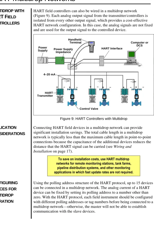
ONTROLLERSHART field controllers can also be wired in a multidrop network (Figure 9). Each analog output signal from the transmitter/controllers is isolated from every other output signal, which provides a cost-effective HART network configuration. In this case, the analog signals are not fixed and are used for the output signal to the controlled device.
Figure 9: HART Controllers with Multidrop
A
PPLICATIONC
ONSIDERATIONSConnecting HART field devices in a multidrop network can provide significant installation savings. The total cable length in a multidrop network is typically less than the maximum cable length in point-to-point connections because the capacitance of the additional devices reduces the distance that the HART signal can be carried (see Wiring and
Installationon page 17).
C
ONFIGURINGD
Using the polling address structure of the HART protocol, up to 15 devices can be connected in a multidrop network. The analog current of a HART
Handheld
Terminal Computer or
DCS Power
Supply HART Interface
HART Transmitter Control Valve 4–20 mA + – + – + – + – + – + – Power Supply Impedance
To save on installation costs, use HART multidrop networks for remote monitoring stations, tank farms,
pipeline distribution systems, and other monitoring applications in which fast update rates are not required.
Control System Interfaces
When you change your existing control system by adding a HART
interface, it is important to understand the complete functionality offered by the HART interface. While several control-system suppliers offer HART interfaces, not all interfaces provide the same functionality.
Control systems such as a DCS, PLC, or SCADA/RTU (remote terminal unit) implement only the functionality required for a given application. For example, a flow-control system may only read the primary variable of a device and provide no additional support for viewing or changing configuration information. Other control-system interfaces provide
comprehensive HART support, maintaining complete configuration records for all connected devices.
Contact your system supplier for specific details on their HART interface(s). Use the form in Appendix A to obtain information from control-system suppliers to identify specific characteristics of their products.
HART I/O
S
UBSYSTEMSMany HART-compatible I/O subsystems have multiple analog channels on each I/O card. Suppliers choose whether to provide one HART interface per channel or to share one HART interface among several channels. The number of shared channels per HART interface impacts the frequency of data updates from a HART field device and the HART functionality that is supported.
HART I/O
FORM
ULTIDROPS
UPPORTFor the best performance and flexibility, one HART interface should be dedicated to each I/O channel. Systems that share only one HART interface among several I/O channels may not support multidrop networks. The effective update rate of a multiplexed interface is slow enough that the performance of multiplexed multidrop networks would not be practical. Some suppliers enable multidrop support by fixing the HART interface to one specific I/O channel. However, the other channels on that card may then not be available for HART communications.
HART I/O
FORB
URSTM
ODES
UPPORTBurst mode is an optional implementation in a field device. Receiving burst mode messages is optional in a host as well. To take full advantage of burst mode, the I/O system should have one HART interface for each channel. If the HART interface is shared by more than one channel, messages sent by the field device may not be detected by the control system. If the system does not have the ability to configure burst mode in the field device, a handheld terminal or other configuration tool is required.
Control System Interfaces
D
ATAH
ANDLING All HART-compatible control systems can read the digital primary variable from a slave device. However, some system architectures may not be able to accommodate textual data (e.g., tag and descriptor fields). In these cases, the controller is able to read the process variable, but may not have direct access to all other data in the HART device.P
ASSTHROUGHF
EATURESome control systems are integrated with a configuration or instrument- management application. In these systems, the control system passes a HART command, issued by the management application, to the field device via its I/O interface. When the control system receives the reply from the field device, it sends the reply to the management application. This function is referred to as a passthrough feature of the control system.
G
ATEWAYS Gateways can be used to bring HART digital data into control systems that do not support HART-capable I/O. Some systems support HART gateways with communication protocols such as Modbus, PROFIBUS DP, or TCP/IP Ethernet. The typical HART gateway supports all universal commands and a subset of the common practice commands. Support varies depending on the gateway supplier. Some gateways support access to device-specific information.SCADA/RTU
S
YSTEMSRTUs used in SCADA systems use a special telemetry to communicate with the control system. RTUs have the same considerations regarding multidrop and burst mode support as other systems. However,
implementation is made more complex because RTUs often communicate to an upper-level host using a communication protocol other than HART (e.g., Modbus). While there are many benefits to implementing HART in an RTU (support of multidrop, burst mode, and multivariable instruments), HART data are only available to the central host system if the telemetry protocol supports the transfer of HART commands or specific HART data (see Multidrop for Tank Farm Monitoringon page 40).
Multiplexers
HART-compatible multiplexers are ideal for users who want to interface with a large number of HART devices. Multiplexers can be modular and are capable of supporting both point-to-point and all-digital (multidrop) HART communication modes. Communication between a multiplexer and a host application depends on the multiplexer capabilities (e.g., RS232C, RS485, Modbus, and TCP/IP Ethernet).
When installing HART multiplexer systems, the following capabilities should be considered:
q Number of HART channels supported
q Number of HART channels that share a HART modem q Burst mode support
q Multidrop support
q Method of communication with the host computer or control system
M
ULTIPLEXERASTHE
P
RIMARYI/O
S
YSTEMHART multiplexers can be used as the primary I/O front end for a
HART-based control or monitoring system (Figure 10). Typically, a PC acts as the host, providing the human-machine interface and performing other high-level functions. The multiplexer continuously monitors the field devices, reports the current readings and instrument status to the host, and passes HART commands from the host computer to the field devices.
Figure 10: HART Multiplexer as the Primary I/O System
P
ARALLELM
ONITORINGWITH AM
ULTIPLEXERWhen a traditional 4–20mA control system is using the analog signals for measurement and control outputs, a HART multiplexer can be added to the network to gain access to the digital HART signal. Using a multiplexer enables a supervisory computer to monitor diagnostics and device status,
Multiplexer
Field Devices
Field Device SCADA GETTINGTHE MOST FROM HART SYSTEMS
Multiplexers
Two types of multiplexers are used in conjunction with a control system. A multiplexer wired in parallel with the field wiring is commonly used when the control system wiring is already in place (Figure 11).
Figure 11: HART Multiplexer with Existing I/O
A multiplexer can also be an integral part of the control system as a third-party I/O (Figure 12). As an I/O system, the multiplexer can include IS barriers and other filtering capabilities and provide services to the field device, such as galvanic isolation or power. For this type of installation, no additional terminations or space are required. The multiplexer can also act as a gateway to convert the HART messages to another protocol such as Modbus, PROFIBUS, or Ethernet.
.
Use a HART multiplexer to gain access to the digital HART signal. Automation and Display System Supervisory Computer Controllers I/O Transmitter Control Valves Multiplexer Controller I/O Supervisory Computer Automation and Display System
Reading HART Data into NonHART Systems
Many HART products are able to perform more than one measurement or output function (e.g., make multiple process measurements, calculate process information, and provide positioner feedback information). All of this information can be easily accessed digitally. However, existing controllers or interface equipment may not have the ability to read digital HART data. Products are available that can read HART digital signals and convert them to analog or contact information, which enables any
traditional analog/digital I/O to take full advantage of the benefits of HART-communicating devices. The Rosemount Inc. Tri-Loop module and the Moore Industries Site Programmable Alarm (SPA) are two such products.
HART
D
ATA-C
ONVERSIONP
RODUCTSThe Tri-Loop module monitors a HART loop for a bursting message and converts three of the four possible variables in HART command number three to analog outputs (Figure 13). The conversion enables the field device to provide a total of four analog signals over a single pair of wires run from the field.
.
Figure 13: Tri-Loop Module Channel 1 Channel 2 Channel 3 Control System Rail-Mounted Tri-Loop Module Field Terminals 4–20 mA Signals for Secondary Variables GETTINGTHE MOST FROM HART SYSTEMS
Reading HART Data into NonHART Systems
The SPA module continuously communicates with any HART-capable device and provides contact closure outputs (alarm trips) based on the information received (Figure 14). For example, the SPA can be configured to monitor the device-status information inherent in the HART
communication protocol and trigger events such as local on/off applications or alarms. The SPA can also initiate emergency shutdown action if
problems are detected with a field device in critical loop applications.
Figure 14: SPA Module
Both HART Tri-Loop and SPA provide multivariable product support on a loop-by-loop basis. 4–20 mA and HART Digital Signals HART Transmitter HART Communicator Process and Diagnostic Data HART Master Annunciator Event Recorder Control System Shutdown Controls
Universal Handheld Communicator
The 275 Universal HART Communicator is available from major
instrumentation suppliers around the globe and is supported by all member companies in the HCF. Using HART DDL, the communicator can fully communicate with and configure any HART device for which it has a DD installed. If the communicator does not have the DD for a particular network device installed, it can still communicate with that device using the universal and common practice commands (see HART Commandson page 7). The HCF provides centralized control and registration for all DDs that can be loaded into the communicator. An index of registered DDs can be found on the world wide web at <http://www.hartcomm.org>.
Figure 15: 275 Universal Handheld Communicator
Use the 275 Universal HART Communicator to communicate with and configure any
HART-communicating device.
PC Configuration Software
Many instrument manufacturers, as well as some independent software developers, offer HART communication software for PCs with capabilities similar to and beyond those offered by a HART handheld communicator.
The software packages listed in Table 4 are used for configuration
management, parameter tuning, and data acquisition with a HART device. The list is not comprehensive, and all software applications are not functionally equivalent. A number of product-specific software
applications are also available for diagnostics. An RS232 HART interface or other interface device connects the PC running the HART application software to the field devices.
S
UMMARYT
ABLEOF
HART
S
OFTWAREUse special software applications to continuously monitor the status of connected field devices and log status changes as they occur, which may help reduce
the costs of regulatory compliance.
Software Application Manufacturer
Asset Management Solutions (AMS)
Configuration and calibration
management Fisher-Rosemount CONF301 HART
Configurator Configuration management Smar International CONFIG Configuration management Krohne
Cornerstone Base Station
Configuration and calibration management
Applied System Technologies Cornerstone
Configurator Instrument configuration
Applied System Technologies H-View Configuration management
and data acquisition Arcom Control Systems IBIS Configuration management EB Hartmann & Braun IBIS Configuration management Samson
K-S Series Configuration management ABB
Mobrey H-View Configuration management KDG Mobrey Pacemaker Configuration management UTSI International
Corporation
Commissioning HART Networks
HART-based instruments have several features that significantly reduce the time required to fully commission a HART network (loop). When less time is required for commissioning, substantial cost savings are achieved.
D
EVICEV
ERIFICATIONBefore installation, manufacturers usually enter device tags and other identification and configuration data into each field instrument. After installation, the instrument identification (tag and descriptor) can be verified in the control room using a configurator (handheld terminal or PC). Some field devices provide information on their physical configuration (e.g., wetted materials)—these and other configuration data can also be verified in the control room. The verification process can be important in conforming to governmental regulations and ISO quality requirements. The commissioning process can be further streamlined by connecting a PC configurator to each HART loop online, either by integration with the control system or by using one of the many available HART multiplexing I/O systems (see Multiplexerson page 26). With this centralized approach, there is no need to move the configuration device from one termination point to the next while commissioning all devices on the network.
L
OOPI
NTEGRITYC
HECKOnce a field instrument has been identified and its configuration data confirmed, the analog loop integrity can be checked using the loop test feature, which is supported by many HART devices. The loop test feature enables the analog signal from a HART transmitter to be fixed at a specific value to verify loop integrity and ensure proper connection to support devices such as indicators, recorders, and DCS displays.
A
S-I
NSTALLEDR
ECORDK
EEPINGA HART configurator also facilitates record keeping. As-installed device configuration data can be stored in memory or on a disk for later archiving or printing.
Use the HART protocol loop test feature to check analog loop integrity and ensure a proper physical
connection among all network devices.
Device Status and Diagnostics
Most HART field instruments provide both status information and diagnostic information. The HART protocol defines basic status
information as information that is included with every message from a field device. Basic status information enables the host application to
immediately identify warning or error conditions detected by the field device. Status messages also enable the user to differentiate between measurements that are outside sensor or range limits and actual hardware malfunctions. Examples of status messages are:
q Field device malfunction q Configuration changed q Cold start
q More status available q Analog output current fixed q Analog output saturated
q Nonprimary variable out of limits q Primary variable out of limits
HART instruments can implement extensive, device-specific diagnostics. The amount and type of diagnostic information is determined by the manufacturer and varies with product and application. Diagnostic information can be accessed using the HART communication protocol. Host applications using DD files can interpret and display diagnostic information. Applications not using DD technology may require product- specific software modules to interpret diagnostic information.
Many manufacturers offer special software applications for their own products. Some modules allow you to customize for specific products. Manufacturers of valve actuators have made extensive use of this capability to provide preventative and predictive diagnostic information that greatly enhances the value of their products as compared to conventional actuators. Several software applications are available that provide continuous
communication with field devices using a HART-compatible multiplexer and HART I/O (see Multiplexerson page 26). These applications provide real-time monitoring of status and diagnostic information.
APPENDICESAPPENDICESAPPENDICES
Connecting a PC to a HART Device or Network
PCs are commonly used for HART host applications for configuration and data acquisition. A specially designed device (Table 5) allows the HART network to be connected to the RS232C serial port or PCMCIA slot of a PC (Figure 16).
Table 5: HART Interfaces
Figure 16: RS232 HART Interface
Product Name Manufacturer
Commubox Endress + Hauser FSK-Modem EB Hartmann & Braun HT311 RS232 Interface Smar International VIATOR PCMCIA HART
Interface MACTek
VIATOR RS232 HART Interface MACTek
Field Device RS232 HART
Interface Handheld Terminal PC/Host
Application
Power Supply GETTINGTHE MOST FROM HART SYSTEMS
PC Application Development Tools
Software drivers are available to assist in the development and integration of PC applications with HART networks. Table 6 shows a partial list of products available.
Table 6: PC Development Tools Product Name Description Manufacturer
Hview Provides DDE server Arcom Control Systems HRT VBX 16-bit Visual Basic driver Borst Automation HRT OCX 32-bit ActiveX Control Borst Automation HART OPC
Server OPC Server
HCF (via member companies)
HL-LinkPro HART driver for LabVIEW Cardiac Systems Solutions
Control in Field Devices
Microprocessor-based smart instrumentation enables control algorithms to be calculated in the field devices, close to the process (Figure 17). Some HART transmitters and actuators support control functionality in the device, which eliminates the need for a separate controller and reduces hardware, installation, and start-up costs. Accurate, closed-loop control becomes possible in areas where it was not economically feasible before. While the control algorithm uses the analog signal, HART communication provides the means to monitor the loop and change control setpoint and parameters.
Figure 17: Transmitter with PID (HART Slave)
Placing control in the field enhances control functionality. Measurement accuracy is maintained because there is no need to transmit data to a separate controller. Control processing takes place at the high update rate of the sensor and provides enhanced dynamic performance.
PC-Based Operator Interface
Muiltiplexer (HART Master) 4–20 mA to Position Valve
Control Valve HART Transmitter
with PID Slave Modbus Link
(RS232) GETTINGTHE MOST FROM HART SYSTEMS
Control in Field Devices
HART F
IELDC
ONTROLLERI
MPLEMENTATIONA HART field controller takes advantage of the HART protocol’s simultaneous analog and digital signaling by converting the transmitter’s traditional analog measurement output into a control output. The analog signal from the smart transmitter (controller) is used to manipulate the field device (Figure 18). The analog output signal also carries the HART digital signal, which is used for monitoring the process measurement, making setpoint changes, and tuning the controller.
Figure 18: Smart Transmitter with PID
The communication rate of the HART protocol (2–3 updates per second) is generally perceived as too slow to support closed-loop control in the central host. With control in the field, the control function no longer depends on the HART protocol’s communication rate. Instead, the control signal is an analog output that is updated at a rate that is much faster than can typically be processed in a conventional control system. Processing rates vary from 2–20 updates per second, depending on the product. The HART digital communication rate remains sufficient for monitoring the control variable and changing setpoint values.
+
Power Supply Smart Transmitter Control Valve Bypass Capacitor ResistorIndustry Applications
Many companies in a wide variety of industries have already realized the advantages of using the HART communication protocol. This section describes some applications in detail and outlines the tangible benefits that result. The applications have been grouped into the following sections:
q Inventory-management applications q Cost-saving applications
q Remote-operation applications q Open-architecture applications
Inventory-Management Applications
Accurate measurements for inventory management are essential in all industries. The HART communication protocol enables companies to make sure inventory management is as efficient, accurate, and low cost as possible.
HART M
ULTIDROPN
ETWORKFORT
ANKL
EVELANDI
NVENTORYM
ANAGEMENTTank level and inventory management is an ideal application for a HART multidrop network (Figure 19). The HART network digital update rate of two PVs per second is sufficient for many tank-level applications. A multidrop network provides significant installation savings by reducing the amount of wiring from the field to the control room as well as the number of I/O channels required. In addition, many inexpensive
process-monitoring applications are commercially available to further cut costs.
Figure 19: Inventory Management with Multidrop
One company uses a HART multiplexer to digitally scan field devices for level-measurement and status information. The information is forwarded to the host application using the Modbus communication standard.
Multivariable instruments further reduce costs by providing multiple process measurements, such as level and temperature, which reduces the wiring and number of process penetrations required.
HART Field Multiplexer Transmitters Storage Tanks INDUSTRY APPLICATIONS
Tanks
Inventory-Management Applications
M
ULTIDROPFORT
ANKF
ARMM
ONITORINGIn one tank farm application, 84 settlement tanks and filter beds on a very large site (over 300,000 m2) are monitored using HART multidrop networks and HART RTUs (see SCADA/RTU Systems on page 25). The HART architecture required just eight cable runs for 84 tanks, with 10–11 devices per run (Figure 20). Over 70 individual runs of over 500 m each were eliminated. Cable savings were estimated at over $40,000 when compared to a conventional installation. RTU I/O was also reduced, which resulted in additional hardware and installation savings. The total installed cost was approximately 50% of a traditional 4–20 mA installation.
Figure 20: Tank Farm Monitoring with Multidrop
INDUSTRY APPLICATIONS HART Multiplexer Storage Control Room Storage Tanks
Inventory-Management Applications
U
NDERGROUNDP
ETROLEUMS
TORAGEWITHHART
C
OMMUNICATION FORA
CCURACYUnderground salt caverns are frequently used for crude oil storage. One customer pumps oil from barges into the storage caverns. An ultrasonic flowmeter records the total flow. To get the oil out of the caverns, a brine solution is pumped into the cavern through a magnetic flowmeter. Brine and crude oil flowing in both directions are measured and reported to the DCS using the HART communication protocol for accuracy. The DCS tracks flow rate and total quantity to maintain a certain pressure inside the caverns (Figure 21).
Figure 21: Underground Petroleum Storage
HART Transmitter Interface Field Instruments Oil Caverns HART Transmitter Interface
Note: Digital accuracy for flow accuracy and flow totals
Cost-Saving Applications
W
ASTEWATERT
REATMENTP
LANTU
PGRADEA Texas wastewater treatment plant replaced stand-alone flowmeters and chart recorder outstations that required daily visits for totalization with a HART system. HART-based magnetic flowmeters were multidropped into HART RTUs to create a cost-effective SCADA network. The use of HART technology reduced system and cable costs, enhanced measurement accuracy, and eliminated time-consuming analog calibration procedures. A system of 11 HART multidrop networks was used to connect 45 magnetic flowmeters from different plant areas. Each flowmeter communicated flow rate and a totalized value over the HART network. Multidrop networks eliminated the need for additional hardware and PLC programming while providing a more accurate totalized value. Complex and costly system integration issues were also avoided—for example, there was no need for synchronization of totals between the host and field PLCs. Multidrop networking further reduced the installation cost by reducing the required number of input cards from the traditional 45 (for point-to-point installations) to 11. Maintenance was simplified because of access to instrument diagnostic and status data.
Use HART multidrop networking to reduce installation and maintenance costs.
Cost-Saving Applications
A
PPLIANCEM
ANUFACTURING WITHM
ULTIDROPA consumer appliance manufacturer used the networking capability of the HART protocol to measure level, flow, and pressure. HART multidrop provided substantial wiring and installation savings as well as digital accuracy with the elimination of the analog to digital (A/D) and digital to analog (D/A) conversions of the instrument and PLC I/O. Figure 22 shows pressure transmitters connected to a PLC via smart transmitter interface multiplexers.
Figure 22: Multidrop Network Example
Storage Tanks Communication Module Smart Transmitter Interface Highway Terminal Block Module PLC INDUSTRY APPLICATIONS
Cost-Saving Applications
R
EMOTER
EZEROINGINAB
REWERYThe benefits of remote monitoring and rezeroing of smart transmitters using the HART protocol are dramatically illustrated in this example of two smart transmitters that control the fluid level in lauter tubs in a brewhouse application. Similar benefits would be realized in any application involving a closed vessel.
Two smart transmitters are installed on each lauter tub—one on the bottom of the tank and the other about nine inches from the bottom. The bottom transmitter is ranged ±40 inH2O; the upper transmitter is ranged
0–30 inH2O. As the lauter tub is filled, the bottom transmitter senses level based on pressure. When the level reaches the upper transmitter, that point is marked as the new zero-level point, and the upper transmitter becomes the primary sensing instrument for the lauter-tub level. The nine-inch zero-level offset from the bottom of the tank is necessary to accommodate loose grain that settles in the bottom of the tank.
Transmitters that are coordinated and working together control fluid level in each lauter tub to within a few barrels. However, the upper transmitter requires periodic maintenance or replacement and rezeroing. An undetected false upper-transmitter level reading can cause a tank level error of up to 40 gallons.
The usual procedure for transmitter rezeroing takes about 95 minutes and has been required as frequently as twice a day. Rezeroing a transmitter using configuration software and PLC interface modules eliminates the need to locate and identify the problem at the site as well as the need for verification by control-room personnel and greatly reduces the chance for inadvertent errors. Estimated total time to rezero each transmitter is reduced to 15 minutes.
Through the configuration software’s instrument-status and diagnostic capabilities, a false level indication can be automatically detected while a lauter tub fill is in progress. The affected transmitter can then be
automatically rezeroed by programming logic in the programmable controller to issue the appropriate command to the instrument.
Cost-Saving Applications
W
ATERT
REATMENTF
ACILITYU
PGRADEHART transmitters and a control system with HART capability were chosen to upgrade a water treatment facility. The completed installation reduced capital, engineering, and installation costs. The process dynamics of the water treatment facility allowed the HART instruments to be used in all-digital mode without compromising plant performance.
The water treatment plant is divided into two areas, each with 14 filters. Each area is controlled by a separate control system for complete
autonomy. A HART network monitors each filter for filter level, filter bed differential, and filter outlet flow. The multidrop installation used a three-wire system in order to accommodate both the two-wire and the four-wire devices (magnetic flowmeters) in use (Figure 23)
(see Multidropon page 6).
Figure 23: Multidrop Networks with 2-Wire and 4-Wire Devices
Because the water treatment facility had a modular design, the use of HART instruments allowed the configuration from the one filter network to be copied to the others, which reduced the implementation time.
Engineering, system configuration, drafting, commissioning, maintenance, and documentation were simplified. A reduced I/O card count also saved money. Main Power 4 mA 12 mA 4 mA Pressure Transmitters Magnetic Flowmeter INDUSTRY APPLICATIONS
Cost-Saving Applications
I
MPROVEDD
IAGNOSTICSA cleaning materials supplier required periodic checkup of the instrument condition and configuration information as compared to the initial
installation. The field transmitters provided a historical record of status changes along with current configuration information. Periodic download of this information was made possible using PLC ladder logic developed for HART instruments.
Remote-Operation Applications
U
NMANNEDO
FFSHOREG
ASP
RODUCTIONWITHHART N
ETWORKSChoosing the HART communication protocol for all-digital communication in a wide-area network enabled one company to have real-time monitoring and control, access to diagnostics, and maintenance capabilities—all from a remote location.
Over half of the 500 transmitters on 15 platforms could be multidropped with update rates of three seconds (six devices), which resulted in
substantial savings in wiring, I/O, and installation. The remaining devices (flowmeters) required a faster response and were wired point to point using digital HART communications to transmit the process data. The flowmeters used the optional burst mode, which provided an update rate of 3.7 times per second. All-digital communications provided maximum accuracy and eliminated potential errors from input scaling, conversion, and drift (see
Multidrop on page 6).
Figure 24: RTU Application
Each platform’s RTU provided a link to approximately 50 temperature, pressure, and flow transmitters (Figure 24). The RTU used the multimaster capability of the HART protocol to enable the second RTU to act as a hot standby, which monitored activity and was able to take over if a failure occurred. The RTUs provided links with the emergency and safety systems and a local interface for maintenance personnel. The Modbus protocol was
Standby RTU Primary RTU Modbus Link HART Multiplexers Transmitters Transmitters Radio Antennae INDUSTRY APPLICATIONS
Remote-Operation Applications
V
ENEZUELAG
AS-L
IFTP
ROJECTIn a Venezuela gas-lift project, HART multidrop technology was used for remote operation of offshore gas-lift production wells at considerable savings (Figure 25):
q 30% decrease in installation costs q 16:1 reduction of input modules q Reduced cost of I/O cards in the RTU q Remot