Training
12/16/09
Scheduling Basics
Introduction:
Goals of the Scheduling Training 4 Scheduling Terminology 5-8
Chapter 1: How to Critique A Schedule:
Critical Path(s) and Float 9,10
Activities Level of Detail & Logic in Sequencing of Tasks 11 Major Issues and Obstacles for the Project 12
Organization of Tasks in Groups (Project Language) 13 Contract Data 14
Baseline 15
Class Exercise (Review Two Schedules) 16,17 Sample Schedule Review Report 18-22
Chapter 2: How to Create A Schedule:
Plan, Plan and then Plan Some More Class Exercise Project 23
Identify Phases within Project 24 Identify Areas within the Phases 24 Identify Components within Areas 24 Identify Activities within Components 24 Identify Activity Codes for Reporting 25,26
Identify Project Constraints, Materials & Methods, Contract Restraints 27 Interview Team Members to Gather Missing Information 27
Determine Best Delivery Method
Best Delivery Method & Presentation of Schedule for Project 28 Class Exercise (Walk through Schedule Preparation Worksheet for a project) 29-32 Scheduling Process Flow Charts
RFP Schedule Process 33 Baseline Schedule Process 34 Update Schedule Process 35 Look Ahead Schedule Process 36
Page
2
Table of Contents-Scheduling
Chapter 3: How to Input A Schedule Into Microsoft
Project:
Data Input
Key to Data Input 37
Project Information & Phase Headers 38 Area Headers within Phases 39
Tasks 39 Durations 40 Activity Codes 41,42 Assign Dependencies 43,44 Calculate Schedule 45
Page
3
Table of Contents-Scheduling
Evaluate
Critical Path 46
Completion vs. Contract Requirements 46 Dependency Assignments 47,48 Adjust
Float Requirements for Critical Path 45 Lag between Predecessors/Successors 49 Predecessors/Successors Modifications 49 Data View-Filters 50,51
Format
Baseline 52-57 Bar Design and Data 58 Tracking Fields 59 Update
Always Save the Original and the Updated 59 Actual Start & Finish Columns 59
Remaining Duration vs. % Complete 59 Scheduling Review 60
Chapter 3 Forms
Activity Code Matrix 61 Activity Code Database 62-66
Goals of this Training:
This is not an in depth training on scheduling; rather it is intended to
show how to critique a schedule as the program manager for a project
and to understand enough of the dynamics of scheduling to communicate
knowledgably to other members of the team. In order to achieve the last
objective listed above, you must know some of the basics on how to
cre-ate a schedule and then how to input it in a scheduling software. For this
reason, the training is divided into three chapters:
Chapter 1: How to Critique A Schedule
Chapter 2: How to Create A Schedule
Chapter 3: How to Input A Schedule Into Microsoft
Project
Page
4
Introduction
Definition of an Effective Schedule:
The project plan must include all aspects of project delivery to be effective. This is
generally associated with:
ο
Establishment of a Work Breakdown Structure (WBS) or Activity Coding Structure.
ο
Development of a procurement strategy (bid package strategy [BPS])
ο
Development of budget structure (GMP format for GMP projects) which reflect the manner in which the
project will be constructed and establishes the format for progress payments as the work proceeds.
ο
Identifying in a detailed manner all activities necessary to complete the work and development of the
rela-tionships among those activities, which dictate their required sequencing in a logical manner with
appropri-ate presumed durations for each activity.
A critical path must be identified. Upon review and acceptance,
Page
5
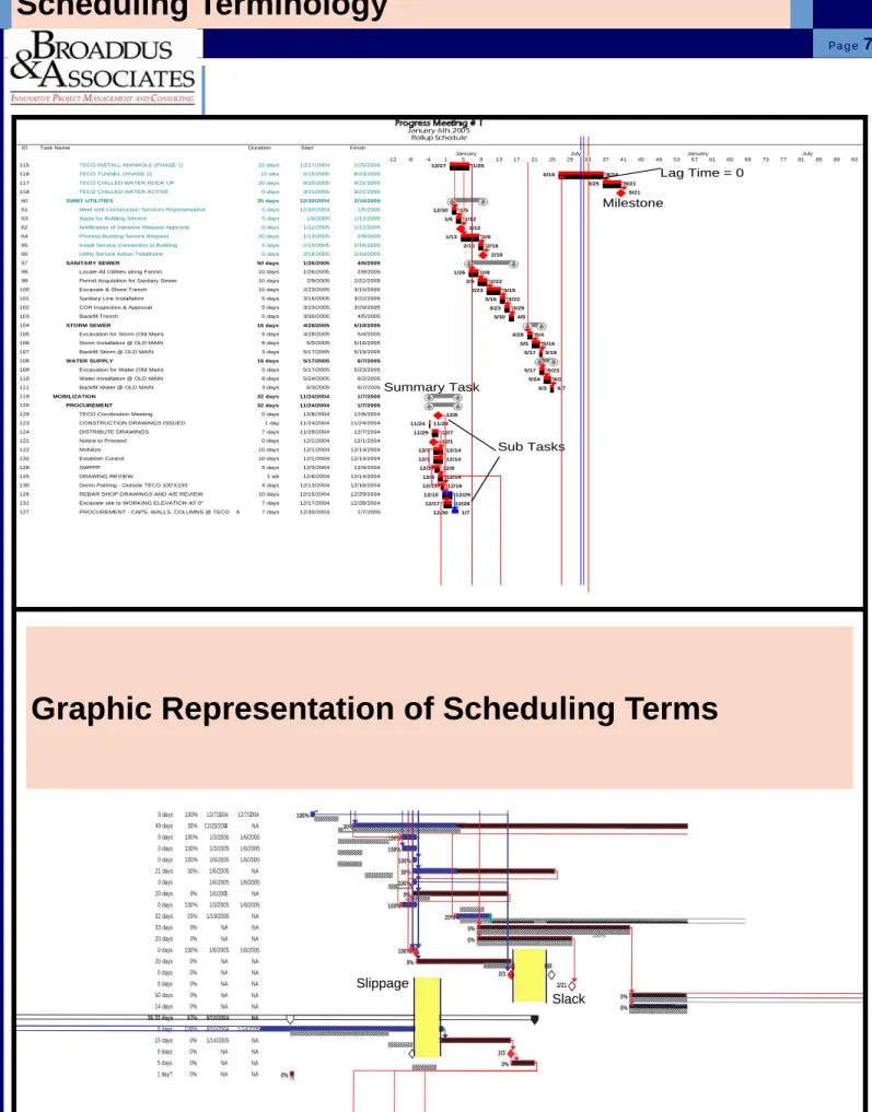
Scheduling Terminology
Scheduling Terminology:
Critical Path
: Longest Path To Complete The Project
Baseline Plan
: Original Schedule
Milestone
: A Significant Point In A Project Which Has No Duration
Lag Time
: Planned Delay Between Tasks
Predecessor
: A Task That Comes Before Another Task And Its
Com-pletion Is Dependent Upon The Following Tasks Start.
Successor
: A Task that comes after another Task.
Lead Time
: Overlap In Two Tasks Which Are Dependent. One Task
Starting Prior To Its Predecessors Completion. Lead Time
rela-tionships are shown below:
Finish to Start (FS): Upon Finish of the Predecessor, the
Suc-cessor can start
Start to Start (SS): Upon start of the Predecessor, the
Successor can start
Start to Finish (SF): Upon start of the Predecessor, the
Successor must finish
Finish to Finish (FF): Upon finish of the Predecessor, the
Successor
must
finish
S
F
Predecessor
Successor
S
S
Predecessor
Successor
S
F
Predecessor
Successor
F
F
Predecessor
Successor
Progress Bar
: Actual Completion Of A Task. Usually Displayed
Adjacent To The Baseline Of The Same Task.
Resource Calendar
: A Calendar Which Indicates The Working Days
Of A Specific Resource.
Summary Task
: A Single Line Task Which Summarizes All The
Tasks Indicated Below It. Usually Shown To Indicate The Total
Duration Of A Phase.
Slack
: The Time A Task Can Be Delayed Without Affecting The
Interdependent Tasks Dates.
Slippage
: The Duration Of Time That A Task Varies From The
Original Baseline Plan. As A General Rule It Indicates A Delay
From The Original Baseline Start Date.
Subtask
: A More Detailed Task Which In Outline Format Comes
Under The Heading Of A Summary Task.
Variance
: The Measure Of Change In A Task Duration Or Resource
Allocation Either In A Positive Or Negative Connotation.
Work Breakdown Structure
: A Coding Structure To Allow Reporting
For Specific Areas Or Trades
Float
: The amount of time that a task can slip before it impacts the
start of the successor task or the critical path.
Page
6
Page
7
Scheduling Terminology
0 days 100% 12/7/2004 12/7/2004 0 days 100% 12/7/2004 12/7/2004 49 days 30% 12/20/2004 NA 0 days 100% 1/3/2005 1/6/2005 0 days 100% 1/3/2005 1/6/2005 0 days 100% 1/6/2005 1/6/2005 21 days 30% 1/6/2005 NA 0 days 100% 1/6/2005 1/6/2005 20 days 0% 1/6/2005 NA 0 days 100% 1/3/2005 1/6/2005 32 days 20% 1/19/2005 NA 33 days 0% NA NA 20 days 0% NA NA 0 days 100% 1/6/2005 1/6/2005 20 days 0% NA NA 0 days 0% NA NA 0 days 0% NA NA 50 days 0% NA NA 14 days 0% NA NA 36.33 days 67% 9/10/2004 NA 0 days 100% 9/10/2004 1/14/2005 15 days 0% 1/14/2005 NA 0 days 0% NA NA 5 days 0% NA NA 1 day? 0% NA NA 100% 100% 30% 100% 100% 100% 30% 100% 0% 100% 20% 0% 0% 100% 0% 2/3 2/21 0% 0% 0% 2/3 0% 0% Slippage SlackID Task Name Duration Start Finish
115 TECO INSTALL MANHOLE (PHASE 1) 22 days 12/27/2004 1/25/2005
116 TECO TUNNEL (PHASE 2) 10 wks 6/16/2005 8/24/2005
117 TECO CHILLED WATER HOOK UP 20 days 8/25/2005 9/21/2005
118 TECO CHILLED WATER ACTIVE 0 days 9/21/2005 9/21/2005
60 SWBT UTILITIES 35 days 12/30/2004 2/16/2005
61 Meet with Construction Services Representative 5 days 12/30/2004 1/5/2005
63 Apply for Building Service 5 days 1/6/2005 1/12/2005
62 Notification of Variance Request Approval 0 days 1/12/2005 1/12/2005
64 Process Building Service Request 20 days 1/13/2005 2/9/2005
65 Install Service Connection to Building 5 days 2/10/2005 2/16/2005
66 Utility Service Active-Telephone 0 days 2/16/2005 2/16/2005
97 SANITARY SEWER 50 days 1/26/2005 4/5/2005
98 Locate All Utilities along Fannin 10 days 1/26/2005 2/8/2005
99 Permit Acquisition for Sanitary Sewer 10 days 2/9/2005 2/22/2005
100 Excavate & Shore Trench 15 days 2/23/2005 3/15/2005
101 Sanitary Line Installation 5 days 3/16/2005 3/22/2005
102 COH Inspection & Approval 5 days 3/23/2005 3/29/2005
103 Backfill Trench 5 days 3/30/2005 4/5/2005
104 STORM SEWER 16 days 4/28/2005 5/19/2005
105 Excavation for Storm (Old Main) 5 days 4/28/2005 5/4/2005
106 Storm Installation @ OLD MAIN 8 days 5/5/2005 5/16/2005
107 Backfill Storm @ OLD MAIN 3 days 5/17/2005 5/19/2005
108 WATER SUPPLY 16 days 5/17/2005 6/7/2005
109 Excavation for Water (Old Main) 5 days 5/17/2005 5/23/2005
110 Water Installation @ OLD MAIN 8 days 5/24/2005 6/2/2005
111 Backfill Water @ OLD MAIN 3 days 6/3/2005 6/7/2005
119 MOBILIZATION 32 days 11/24/2004 1/7/2005
120 PROCUREMENT 32 days 11/24/2004 1/7/2005
129 TECO Corrdination Meeting 0 days 12/8/2004 12/8/2004
123 CONSTRUCTION DRAWINGS ISSUED 1 day 11/24/2004 11/24/2004
124 DISTRIBUTE DRAWINGS 7 days 11/29/2004 12/7/2004
121 Notice to Proceed 0 days 12/1/2004 12/1/2004
122 Mobilize 10 days 12/1/2004 12/14/2004
132 Establish Control 10 days 12/1/2004 12/14/2004
128 SWPPP 5 days 12/3/2004 12/9/2004
125 DRAWING REVIEW 1 wk 12/8/2004 12/14/2004
130 Demo Parking - Outside TECO 100'X100' 4 days 12/13/2004 12/16/2004
126 REBAR SHOP DRAWINGS AND A/E REVIEW 10 days 12/15/2004 12/29/2004
131 Excavate site to WORKING ELEVATION 40'-0" 7 days 12/17/2004 12/28/2004
127 PROCUREMENT - CAPS, WALLS, COLUMNS @ TECO A 7 days 12/30/2004 1/7/2005
12/27 1/25 6/16 8/24 8/25 9/21 9/21 12/30 1/5 1/6 1/12 1/12 1/13 2/9 2/10 2/16 2/16 1/26 2/8 2/9 2/22 2/23 3/15 3/16 3/22 3/23 3/29 3/30 4/5 4/28 5/4 5/5 5/16 5/17 5/19 5/17 5/23 5/24 6/2 6/3 6/7 12/8 11/24 11/24 11/29 12/7 12/1 12/1 12/14 12/1 12/14 12/3 12/9 12/8 12/14 12/13 12/16 12/15 12/29 12/17 12/28 12/30 1/7 -12 -8 -4 1 5 9 13 17 21 25 29 33 37 41 45 49 53 57 61 65 69 73 77 81 85 89 93
January July January July
January 6th, 2005 Rollup Schedule Lag Time = 0 Milestone Summary Task Sub Tasks
Page
8
Scheduling Terminology
100% 0% 0% 0% 0% 3/2 0% 100% 100% 0% 100% 12/1 0% 0% 0% 100% 100% 100% 100% 1/12 27% 12/1 100% 100% 14% 100% 0% 1/3 0% 0% 2/14 0% 0% 0% 0% 0% 12/8 100% 12/1 100% 100% 100% 100% 100% 100% 100%Baseline
Actual Activity Progress
Deadline
Ahead of Schedule
Lead Time
Predecessor
Page
9
Chapter 1-How to Critique A Schedule
Critical Path & Float:
1.
The 1st thing you should look for is the critical path for the project.
This is usually illustrated graphically as activities that are “red”. The
connecting relationship lines will also appear “red”.
2.
Another way to determine the critical path is to review the options of
the schedule for float. Most programs allow the scheduler to establish
the number of days of float as the critical path. (I.e. 0 days of activity
float is usually the critical path, but 1 or 2 days of float per activity can
also be set as the critical path.)
3.
Scheduling programs also typically allow you to select if you want to
view multiple critical paths. Whether or not you chose this option
de-pends upon the complexity of the project. Typically the more complex
a project is, then it would be appropriate to display more than one
criti-cal path. However, caution is needed when showing more than one
critical path. It can become easy to distract the attention away from
the real focus of the project.
ID Task Name Duration Start Finish
1 PROJECT DURATION 416 days 11/24/2004 6/28/2006
2 Notice to Proceed 0 days 12/1/2004 12/1/2004 3 Mobilize 10 days 12/1/2004 12/14/2004 4 CONSTRUCTION DRAWINGS ISSUED 1 day 11/24/2004 11/24/2004 5 DISTRIBUTE DRAWINGS 7 days 11/25/2004 12/3/2004 6 DRAWING REVIEW 1 wk 12/6/2004 12/10/2004 7 REBAR SHOP DRAWINGS AND A/E REVIEW 10 days 12/13/2004 12/24/2004 8 PROCUREMENT - CAPS, WALLS, COLUMNS 7 days 12/27/2004 1/4/2005 9 SWPPP 5 days 12/3/2004 12/9/2004 10 Establish Control 10 days 12/1/2004 12/14/2004 11 TECO Coordination Meeting 0 days 12/8/2004 12/8/2004 12 Demo Parking - Outside TECO 100'X100' 4 days 12/13/2004 12/16/2004 13 Excavate site to WORKING ELEVATION 40'-0" 7 days 12/17/2004 12/27/2004 14 TECO MOBILIZE 4 days 12/20/2004 12/23/2004 15 TECO INSTALL MANHOLE (PHASE 1) 22 days 12/24/2004 1/24/2005 16 TECO TUNNEL (PHASE 2) 10 wks 6/15/2005 8/23/2005
17 AUGER CAST PILES/PILE CAPS 61 days 12/22/2004 3/16/2005
18 AREA "S" 23 days 12/22/2004 1/21/2005
19 (27) GL G.2/1, G.2/2, J/1, J/2 19 days 12/22/2004 1/17/2005
20 Drill Piles (45 EA) 3 days 12/22/2004 12/24/2004 21 Install Retention System 3 days 12/27/2004 12/29/2004 22 Excavate to Bottom of Pier Cap 1 day 12/30/2004 12/30/2004 23 Reinforce 2 days 1/5/2005 1/6/2005 24 Form Cap 1 day 1/7/2005 1/7/2005 25 Pour Cap 1 day 1/10/2005 1/10/2005 26 Reinforce Column 2 days 1/11/2005 1/12/2005 27 Form Column 2 days 1/13/2005 1/14/2005 28 Pour Column 1 day 1/17/2005 1/17/2005
29 (26) GL J/3 13 days 12/27/2004 1/12/2005
30 Drill Piles (12 EA) 1 day 12/27/2004 12/27/2004 31 Reinforce 1 day 1/5/2005 1/5/2005 32 Form Cap 1 day 1/6/2005 1/6/2005 33 Pour Cap 1 day 1/7/2005 1/7/2005 34 Reinforce Column 1 day 1/10/2005 1/10/2005 35 Form Column 1 day 1/11/2005 1/11/2005 36 Pour Column 1 day 1/12/2005 1/12/2005
37 (25) GL H/3 12 days 12/28/2004 1/12/2005
38 Drill Piles (17 EA) 1 day 12/28/2004 12/28/2004 39 Reinforce 1 day 1/5/2005 1/5/2005 40 Form Cap 1 day 1/6/2005 1/6/2005 41 Pour Cap 1 day 1/7/2005 1/7/2005 42 Reinforce Column 1 day 1/10/2005 1/10/2005 43 Form Column 1 day 1/11/2005 1/11/2005 44 Pour Column 1 day 1/12/2005 1/12/2005
45 (24) GL J/4 11 days 12/29/2004 1/12/2005
46 Drill Piles (12 EA) 1 day 12/29/2004 12/29/2004 47 Reinforce 1 day 1/5/2005 1/5/2005 48 Form Cap 1 day 1/6/2005 1/6/2005 49 Pour Cap 1 day 1/7/2005 1/7/2005
12/1
12/8
38 42 46 50 1 5 9 13 17 21 25 29 33 37 41 45 49 1 5 9 13 17 21 25 29 January July January July
Page 1
Original Schedule by GC
No Critical Path Shown
Revised Schedule after Review by B&
Critical Path Shown
Float Evaluation:
1.
A quick way to determine if the critical path has been properly
calcu-lated would be to run a float report.
2. In the example shown below, the total float (days), is far greater than
it should be. This would indicate that the dependency of the tasks
have not been properly linked.
3. It is also helpful to review whether a
predecessor and successor
has been assigned to each activity
. There should only be a
mini-mum of activities that don’t have both a predecessor and successor.
Page
10
Chapter 1-How to Critique A Schedule
Locatio ACT ID Activity Description OD RD ES EF TF Predecessors Successors
CW A0502 MEP ROUGH BELOW SLAB 1ST FLOOR 7 0 04NOV04 29NOV04 A0402, A0500 A0504 CW A0500 DRILL PIERS 7 0 29SEP04 18OCT04 A0001 A0502 CONC - CONCRETE FOR SUSPENDED STRUCTURAL SLABS
CONCA0500.3 STRIP & RESHORE DECK ROOF EAST 1 1 15FEB05 15FEB05 112d A0A0400.4E, A0A0500.2E
CONCA0500.2 POUR SLAB & BEAMS ROOF EAST 1 1 11FEB05 11FEB05 112d A0A0500.1E A0A0500.3E CONCA0500.1 REBAR SLAB & BEAMS ROOF EAST 2 2 09FEB05 10FEB05 112d A0A0500E A0A0500.2E CONCA0400.4 STRIP & RESHORE DECK 4TH FLOOR 1 1 08FEB05 08FEB05 116d A0A0300.4E, A0A0400.2E A0A0500.3E CONC0A0500EFORM DECK & BEAMS @ ROOF EAST 3 3 07FEB05 09FEB05 112d A0A0400.3E A0A0500.1E CONCA0400.3 COLUMNS BETWEEN 4TH FLOOR & 2 2 04FEB05 07FEB05 112d A0A0400.2E A0A0500E CONCA0400.2 POUR SLAB & BEAMS 4TH FLOOR 1 1 03FEB05 03FEB05 112d A0A0400.1E A0A0400.3E, A0A0400.4E CONCA0400.4 STRIP & RESHORE DECK @ ROOF 3 3 02FEB05 04FEB05 119d A0A0300.4W, A0A0400.2W
CONCA0400.1 REBAR SLAB & BEAMS 4TH FLOOR 3 3 31JAN05 02FEB05 112d A0A0400E A0A0400.2E CONCA0400.2 POUR SLAB & BEAMS ROOF WEST 1 1 28JAN05 28JAN05 119d A0A0400.1W A0A0400.4W CONCA0300.3 COLUMNS BETWEEN 3RD & 4TH 2 2 26JAN05 27JAN05 112d A0A0300.2E A0A0400E CONCA0300.4 STRIP & RESHORE DECK 3RD FLOOR 4 4 26JAN05 31JAN05 121d A0A0200.4E, A0A0300.2E A0A0400.4E CONCA0400.1 REBAR SLAB & BEAMS ROOF WEST 2 2 26JAN05 27JAN05 119d A0A0400W A0A0400.2W CONC0A0400EFORM DECK 4TH FLOOR EAST BLDG 4 4 26JAN05 31JAN05 112d A0A0300.3E A0A0400.1E CONCA0300.2 POUR SLAB & BEAMS 3RD FLOOR 1 1 25JAN05 25JAN05 112d A0A0300.1E A0A0300.3E, A0A0300.4E CONC0A0400WFORM DECK & BEAMS @ ROOF WEST 4 4 24JAN05 27JAN05 119d A0A0200.4W, A0A0300.3W, A0A0300W A0A0400.1W CONCA0300.4 STRIP & RESHORE DECK 3RD FLOOR 4 4 21JAN05 26JAN05 123d A0A0300.2W A0A0400.4W CONCA0300.1 REBAR SLAB & BEAMS 3RD FLOOR 3 3 20JAN05 24JAN05 112d A0A0300E A0A0300.2E CONCA0300.3 COLUMNS BETWEEN 3RD FLOOR & 3 3 20JAN05 24JAN05 119d A0A0300.2W A0A0400W CONCA0300.2 POUR SLAB & BEAMS 3RD FLOOR 1 1 19JAN05 19JAN05 119d A0A0300.1W A0A0300.3W, A0A0300.4W CONCA0200.4 STRIP & RESHORE DECK 2ND FLOOR 4 4 18JAN05 21JAN05 123d A0A0200.2E A0A0300.4E CONCA0300.1 REBAR SLAB & BEAMS 3RD FLOOR 2 2 17JAN05 18JAN05 119d A0A0300W A0A0300.2W CONC0A0300EFORM DECK 3RD FLOOR EAST BLDG 4 4 17JAN05 20JAN05 112d A0A0200.3E A0A0300.1E CONCA0200.3 COLUMNS BETWEEN 2ND & 3RD 2 2 14JAN05 17JAN05 112d A0A0200.2E A0A0300E CONCA0200.2 POUR SLAB & BEAMS 2ND FLOOR 1 1 13JAN05 13JAN05 112d A0A0200.1E A0A0200.3E, A0A0200.4E CONC0A0300WFORM DECK 3RD FLOOR WEST BLDG 4 4 12JAN05 17JAN05 119d A0A0200.3W A0A0300.1W, A0A0400W CONCA0200.4 STRIP & RESHORE DECK 2ND FLOOR 4 4 11JAN05 14JAN05 124d A0A0200.2W A0A0400W CONCA0200.1 REBAR SLAB & BEAMS 2ND FLOOR 3 3 10JAN05 12JAN05 112d A0A0200E A0A0200.2E CONCA0200.3 COLUMNS BETWEEN 2ND & 3RD 3 3 10JAN05 12JAN05 119d A0A0200.2W A0A0300W CONCA0200.2 POUR SLAB & BEAMS 2ND FLOOR 1 0 08JAN05 08JAN05 A0A0200.1W A0A0200.3W, A0A0200.4W CONC0A0200EFORM DECK 2ND FLOOR EAST BLDG 4 1 04JAN05 07JAN05 112d A0A0100.1E, A0A0200W A0A0200.1E CONCA0200.1 REBAR SLAB & BEAMS 2ND FLOOR 2 0 31DEC04 06JAN05 A0A0200W A0A0200.2W CONCA0100.1 COLUMNS BETWEEN 1ST & 2ND 3 0 30DEC04 03JAN05 A0A0100.1W A0A0200E CONC0A0200WFORM DECK 2ND FLOOR WEST BLDG 4 0 20DEC04 06JAN05 A0A0100, A0A0100.1W A0A0200.1W, A0A0200E CONCA0A0100 MOBILIZE 5 0 15DEC04 21DEC04 A0A0100.1W A0A0200W
Page
11
Chapter 1-How to Critique A Schedule
Activities (Level of Detail):
1.
Again, the level of detail is dependent upon the complexity of the
pro-ject. Generally speaking, the activities or processes which are
un-usual or complicated
, would require a more detailed listing.
Remem-ber the key to any schedule is the ability of it’s end users to
under-stand it’s content. Therefore, clarity is of the utmost importance.
Therefore, if detail of a complex process will enable the persons using
the schedule to understand the process, then detail is warranted.
2.
Another point to remember when deciding on the level of detail in your
identification of tasks, is the
amount of work which will be required
to update the schedule
. In order for a schedule to be useful, it must
be updated regularly. Therefore, if a $200,000 project had 3,000
ac-tivities, and this would require 2 days to update, then it would be
pru-dent to reconsider the level of activity details.
Reinforce
Start: 4/18/05 ID: 411 Finish: 4/20/05 Dur: 3 days Res:
Pour
Start: 4/21/05 ID: 412 Finish: 4/21/05 Dur: 1 day Res:
Reinforce
Start: 4/22/05 ID: 414 Finish: 4/22/05 Dur: 1 day Res:
Excavate/Carton Forms
Start: 4/19/05 ID: 419 Finish: 4/21/05 Dur: 3 days Res:
Reinforce
Start: 4/21/05 ID: 420 Finish: 4/25/05 Dur: 3 days Res:
Pour
Start: 4/26/05 ID: 421 Finish: 4/27/05 Dur: 2 days Res:
Page 143
Logic In Sequencing of Activities:
1.
The next step in reviewing a schedule is to examine the accuracy in the sequencing of
Major Issues & Obstacles for the Project:
1. The objective of any schedule is to accurately represent the major
is-sues and obstacles that may interfere with the project completion by
the designated deadline. Therefore, the most important part of a
schedule, other than the critical path, is that the major issues be
in-cluded, regardless if they are under your control or not.
2. In the example below, one of the major project constraints is that the
team will have to close one of the major streets in order to complete
the necessary utility work.
3. Major issues of the project shown below is all of the utility work that is
located adjacent to the property. The contractor failed to include it in
the original schedule because they were not responsible for the scope
of work, yet it has a big impact on when their work can commence.
Page
12
Chapter 1-How to Critique A Schedule
ID Task Name Baseline Start Baseline Finish Projected Start Projected Finish Remaining Duration % Complete Actual Start 61 TWU Approve Estimate for Underground Ser v 12/30/2004 1/12/2005 1/6/2005 1/6/2005 0 days 100% 1/6/2005
62 Deposit Check to CPE from TWU 1/13/2005 1/19/2005 1/12/2005 1/12/2005 0 days 100% 1/12/2005
63 Revise TNC Agreement by CPE 1/13/2005 1/26/2005 1/12/2005 1/25/2005 10 days 0% 1/12/2005
64 CPE Public Plan & Profile Plans 1/20/2005 2/23/2005 1/12/2005 2/15/2005 25 days 0% 1/12/2005
65 TWU Execute TNC Agreement 1/27/2005 2/2/2005 1/26/2005 2/1/2005 5 days 0% NA
66 COH Permit for Public Plan & Profile Plans 2/24/2005 3/9/2005 2/16/2005 3/1/2005 10 days 0% NA
68 Close Old Main Street 3/10/2005 3/10/2005 3/2/2005 3/2/2005 0 days 0% NA
69 CPE Construct Public Underground Duct Ba n 3/10/2005 3/30/2005 3/2/2005 3/22/2005 15 days 0% NA
72 Vault Service 12/22/2004 9/28/2005 11/19/2004 11/1/2005 237.5 days 4% 11/19/2004
74 TWU Approve Estimate of Vault Service 12/30/2004 1/12/2005 1/6/2005 1/6/2005 0 days 100% 1/6/2005
75 Order Transformer Equipment 1/19/2005 1/19/2005 1/19/2005 1/19/2005 0 days 100% 1/19/2005
76 Transformer Fabrication 1/20/2005 3/16/2005 1/20/2005 8/3/2005 140 days 0% 1/20/2005
77 AIA Revised Vault Plan NA NA 1/3/2005 1/12/2005 0 days 100% 1/3/2005
78 Revised Stub Locations From CPE NA NA 12/1/2004 12/1/2004 0 days 0% NA
79 Apply for Building Service 1/20/2005 1/26/2005 1/20/2005 1/26/2005 5 days 0% NA
80 TWU Execute TNC Agreement 1/27/2005 2/2/2005 1/12/2005 1/18/2005 5 days 0% 1/12/2005
81 Process Building Service Request 1/27/2005 2/2/2005 1/27/2005 2/2/2005 5 days 0% NA
87 Fannin Existing Duct Bank 1/12/2005 1/12/2005 12/21/2004 12/21/2004 0 days 100% 12/21/2004
88 Notification of Variance Request Approval 1/12/2005 1/12/2005 12/21/2004 12/21/2004 0 days 100% 12/21/2004 89 ENTEX UTILITIES 12/30/2004 1/12/2005 12/20/2004 1/12/2005 0 days 100% 12/20/2004
90 Meet with Construction Services Representative 12/30/2004 1/5/2005 12/20/2004 12/20/2004 0 days 100% 12/20/2004 91 Notification of Variance Request Approval 1/12/2005 1/12/2005 1/12/2005 1/12/2005 0 days 100% 1/12/2005 92 TECO UTILITIES 12/1/2004 3/9/2005 12/1/2004 9/21/2005 153.13 days 27% 12/1/2004
93 TECO Coordination Meeting 12/8/2004 12/8/2004 12/1/2004 12/1/2004 0 days 100% 12/1/2004
94 TECO MOBILIZE 12/20/2004 12/23/2004 12/20/2004 12/23/2004 0 days 100% 12/20/2004
95 TECO INSTALL MANHOLE (PHASE 1) 12/27/2004 1/25/2005 12/20/2004 1/20/2005 0 days 100% 12/20/2004
99 SWBT UTILITIES 12/30/2004 2/16/2005 1/3/2005 2/14/2005 26.57 days 14% 1/3/2005
100 Meet with Construction Services Representative 12/30/2004 1/5/2005 1/3/2005 1/3/2005 0 days 100% 1/3/2005
101 Apply for Building Service 1/6/2005 1/12/2005 1/4/2005 1/10/2005 5 days 0% NA
102 Notification of Variance Request Approval 1/12/2005 1/12/2005 1/3/2005 1/3/2005 0 days 100% 1/3/2005
103 Process Building Service Request 1/13/2005 2/9/2005 1/11/2005 2/7/2005 20 days 0% NA
104 Install Service Connection to Building 2/10/2005 2/16/2005 2/8/2005 2/14/2005 5 days 0% NA
105 Utility Service Active-Telephone 2/16/2005 2/16/2005 2/14/2005 2/14/2005 0 days 0% NA
106 SANITARY SEWER 1/26/2005 4/5/2005 1/21/2005 3/31/2005 50 days 0% NA
107 Locate All Utilities along Fannin 1/26/2005 2/8/2005 1/21/2005 2/3/2005 10 days 0% NA 108 Permit Acquisition for Sanitary Sewer 2/9/2005 2/22/2005 2/4/2005 2/17/2005 10 days 0% NA 109 Excavate & Shore Trench 2/23/2005 3/15/2005 2/18/2005 3/10/2005 15 days 0% NA 110 Sanitary Line Installation 3/16/2005 3/22/2005 3/11/2005 3/17/2005 5 days 0% NA
121 MOBILIZATION 11/24/2004 1/7/2005 11/24/2004 1/7/2005 0 days 100% 11/24/2004
122 PROCUREMENT 11/24/2004 1/7/2005 11/24/2004 1/7/2005 0 days 100% 11/24/2004
123 TECO Corrdination Meeting 12/8/2004 12/8/2004 12/8/2004 12/8/2004 0 days 100% 12/8/2004 125 DISTRIBUTE DRAWINGS 11/29/2004 12/7/2004 11/29/2004 12/7/2004 0 days 100% 11/29/2004 126 Notice to Proceed 12/1/2004 12/1/2004 12/1/2004 12/1/2004 0 days 100% 12/1/2004 127 Mobilize 12/1/2004 12/14/2004 12/1/2004 12/14/2004 0 days 100% 12/1/2004 128 Establish Control 12/1/2004 12/14/2004 12/1/2004 12/14/2004 0 days 100% 12/1/2004
Project
Constraint
Major
Issues
Page
13
Chapter 1-How to Critique A Schedule
Project Language (Organization of Tasks In
Groups Which Emphasize Areas of the Project):
1.
Projects are generally complicated enough on their own, so the intent
should be to simplify the process as much as possible. For that
rea-son, it is important to create a simplistic language that all parties
work-ing on the job can relate to durwork-ing meetwork-ings and plannwork-ing sessions.
This simplistic nomenclature is what is referred to as the
Project
Lan-guage.
As you can see in the example below, the project has been
broken down into 3 sections:
Area “N” = North Zone
Area “C” = Central Zone
Area “S” = South Zone
2.
This language will be used in all meetings and throughout the
Contract Data:
1. As with all schedules, the objective is to make a specific deadline date
per the contract. Therefore, it only makes sense to include line items
in the schedule that represent what the actual time line goal is.
2. In the example below, activities 275-276 represent the original
con-tract agreement.
3. Activity 279 represent the delay days claimed by the contractor.
4. Activity 278 represents the delay days that are approved by the
Owner of the project. Once days are approved in this line item,
activ-ity 277 will be extended to represent the new substantial completion
date. (In order for this to occur, activity 278 must be a predecessor to
activity 277).
5. Not shown in the example below is an additional activity which is
called “
Actual Projected Completion by Contractor
”. The predecessor
to this activity would be the last activity by the contractor to complete
the construction portion of the contract. This enables a quick
refer-ence on the schedule to the required completion date as well as the
contractors projected ability to meet that completion date.
Page
14
Page
15
Chapter 1-How to Critique A Schedule
Baseline:
1.
Every project should have a baseline established prior to
updat-ing it with any progress dates
. Besides being able to track progress
against the baseline (reference point), the other reason for
establish-ing this, is to create buy in by all participants that the plan established
is the best to accomplish the project goal. Without buy in by the
Owner of the project, it becomes almost impossible to extend the
schedule due to any weather or change in scope delays.
2.
As the example is shown below, it enables a quick analysis of whether
the schedule is ahead or behind. With this assessment, the planner
can then make adjustments for the remaining unfinished activities. As
with all projects, the sooner these adjustments are made the better
chance you have of making the original deadline.
CLASS COMPARISON EXERCISE
CPM Not Utilizing Principles of Scheduling:
Page
16
Page
17
Chapter 1-How to Critique A Schedule
Review Schedules for Technique & Content:
1. Refer to “Wheeler Housing Project” as a sample report.
Page