An Extensible, Portable, Scalable Cluster Management Software Architecture
James H. Laros III ,
Lee Ward , Nathan W. Dauchy
†, Ron Brightwell
Trammell Hudson
‡, Ruth Klundt
§Sandia National Laboratories
PO Box 5800
Albuquerque, NM, 87185
Abstract
This paper describes an object-oriented software archi-tecture for cluster integration and management that enables extensibility, portability, and scalability. This architecture has been successfully implemented and deployed on several large-scale production clusters at Sandia National Labora-tories, the largest of which is currently 1861 nodes. This paper discusses the key features of the architecture that al-low for easily extending the range of supported hardware devices and network topologies. We also describe in detail how the object-oriented structure that represents the hard-ware components can be used to implement scalable and portable cluster management tools.
Keywords: Cluster Management, Commodity Clusters, Cluster Architecture, Commercial Off The Shelf (COTS)
1. Introduction
Commodity clusters, for the purpose of this paper, are defined as cluster systems composed of a wide range of COTS devices, coupled by one or more networks. These networks can provide inter-node communication, diagnos-tic support or other communication requirements. The de-vices are not limited to computational nodes. Because of the nature of commodity clusters, support devices are also a critical consideration in a software architecture that can be
Corresponding Author [email protected], Sandia is a multiprogram laboratory operated by Sandia Corporation, a Lockheed Martin Company, for the United States Department of Energy under contract DE-AC04-94AL85000.
jhlaros,lee,[email protected]
†[email protected], Contractor to Sandia National Labs from High
Performance Technologies, Inc., 4121 Wilson Boulevard, Suite 200, Ar-lington, VA 22203-1839
‡[email protected], Currently affiliated with Celera
Ge-nomics, 45 West Gude Drive, Rockville, MD 20850
§[email protected], Contractor to Sandia National Labs from
Com-paq Computer Corporation, P.O. Box 692000, Houston, Texas 77269-2000
implemented on a wide range of clusters. Common device types found in COTS clusters are:
Nodes Devices that provide computation capability to the cluster, often chosen based on the application to be performed on the cluster. Node devices are frequently COTS high-speed workstations of various chip archi-tectures and number of processors, and can be con-figured with a wide variety of resources. Nodes can be loosely coupled servers in a web farm, distributed tightly or loosely coupled computational resources, ad-ministrative nodes, diagnostic nodes, I/O proxy nodes, or nodes designed to meet other site-specific require-ments. Nodes can also be used in a support role to provide resources to other nodes that are deeper in a hierarchically architected cluster.
Terminal Servers Devices that provide serial console ac-cess to nodes and other device types for acac-cess to these devices during all states of initialization and operation. Power Controllers Devices that provide a means of con-trolling the power supply to devices. Recent node type devices often provide this capability from the serial port of the node device itself.
Network Devices Hubs and switches used for diagnostic networks, which enable remote management of de-vices, and for specialized networks that enable high-speed process communication for parallel processing applications, a common use of commodity clusters. To be useful in support of both current and next genera-tion cluster systems a software-architecture must be exten-sible enough to support simple addition of new devices and device types. In addition, the software architecture must support current and future network topologies. Of primary interest are networks that can be leveraged for cluster man-agement. New device technologies enable new clusters to
be architected differently from their predecessors. The re-sulting network topology should be supported without af-fecting the software architecture. In Section 3, we will dis-cuss an abstraction that allows us to support current and fu-ture devices independent of cluster topology.
To achieve the highest degree of portability all cluster management tools should get the information they need from a central database. This database should describe de-vice make up and network topology of the cluster. In Sec-tion 4, we will discuss how to leverage the device hierarchy to produce a database that represents a specific cluster. In Section 5, we will describe how to leverage the database in a portable way to produce tools for cluster management. In Section 6, we will discuss aspects of the software architec-ture that enhance cluster scalability; a key aspect of which is management support for hierarchical hardware architec-tures that allow clusters to scale to thousands of nodes.
2. Related Work
Cluster management tools have been an area of intense development over the last few years. Since 1997 when the CplantTM[1] project began, the interest in efficient sys-tem administration tools for clusters has steadily increased. Commercial vendors and open-source development groups have produced several tool-sets of varying capability. The architecture described in this paper was developed after ex-perimentation with our own set of cluster management tools that were designed and implemented for the initial CplantTM clusters. We realized soon after these systems were de-ployed that these tools were insufficient. In re-evaluating our approach, we developed a set of several key functional and performance requirements, which include:
Support diskless as well as diskfull nodes
Support a wide-range of node and management hard-ware
Support a tightly-integrated cluster of 10,000 nodes Support multiple software environments at the node level
Support switching between classified/unclassified net-works
Support a hierarchical administrative network
Separate management tools and parallel runtime sys-tem
Manage cluster as a single system Do not require kernel modifications
Do not effect performance of compute nodes Be usable by cluster non-experts
Boot in less than one-half hour
We evaluated several different cluster management pack-ages available at that time. While our search was not ex-haustive, each tool that we investigated failed to meet at least one of our fundamental requirements. Since most of these tools are limited in extensibility and portability, we were not able to tailor them to meet our needs.
One promising cluster management package was used by the Chiba City [2] project at Argonne National Laboratory, where the administrative network hierarchy was modeled after the one used for CplantTM. However, the City Toolkit did not support diskless nodes and relied on floppy disks in booting nodes. Because all of our compute nodes are disk-less and have no floppy drives, these tools were insufficient. Because these tools were hardcoded to understand the hi-erarchical administrative network, they were difficult to ex-tend to support diskless nodes and alternative management network topologies.
Like Chiba City, the VA Cluster Management (VACM)[3] product from VA Linux (now VA Soft-ware) was also modeled after the network hierarchy of CplantTM. However, it too relied on diskfull nodes and only supported Intel[4] x86 hardware.
The Cluster Cockpit tool from TurboLinux[5] was de-veloped by one of the original implementers of the first CplantTM cluster administration toolset. Over the course of several detailed discussions, we learned that this tool was really intended to support web farms and had some in-herent scalability limitations that would prohibit its use on CplantTM.
Compaq’s Cluster Management Utility (CMU)[6] pro-vided a nice graphical user interface, but was designed to in-dependently manage individual stand-alone systems where all nodes have identical hardware and need to be identically configured. At the time of evaluation, CMU only supported the Tru64 UNIX operating system.
The Beowulf product from Scyld[7] provided extremely easy installation and management of compute nodes. How-ever, the administration tools were tightly bundled into the parallel runtime system. There was no easy way to separate the cluster management functions from the environment needed to launch and interact with parallel jobs. Scyld’s approach also requires significant Kernel modifications.
The Rocks[8] tool from NPACI provides installation tools and mechanisms to keep cluster nodes in a consistent software state. It distributes RPM files to diskfull nodes, which install using Linux Kickstart. Rocks assumes that each node needs a full set of RPM files. As such, it takes several minutes to complete an installation on a single node, and would require several hours for thousand-node systems.
Clusterworx[9] from LinuxNetworx provides an extensi-ble architecture for adding administration and monitoring of nodes. Unfortunately, the implementation requires an agent running on each node in the system, which degrades the performance of compute nodes. And, in order to be fully functional, additional vendor-specific hardware is needed for administrative functions and remote power control.
3. Class Hierarchy
3.1. Structure (top of the hierarchy)
None of the above approaches to cluster management satisfied all our functional and performance requirements, particularly supporting current commodity devices that serve a range of purposes and also allowing for ease of in-tegration for new devices and purposes. To provide this, we have developed a strategy to produce a hierarchical repre-sentation of the devices that exist in the cluster. Similar to the “device driver” concept, this Class Hierarchy describes the capabilities of the corresponding hardware in a consis-tent way that can be leveraged by higher level tools. It is hierarchical to provide for inheritance and virtually unlim-ited extensibility.
Device
Equipment
Node
Power
Alpha
DS10
Network
TermSrvr
RPC3
ETS
Dec90PM
DS_RPC
DS10
DS_RPC
Miata
Monet
Intel
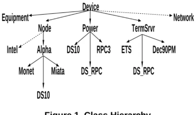
Figure 1. Class Hierarchy
The device Class Hierarchy is implemented as the Device class and its sub-classes. At the highest level of the Class Hierarchy classes are most generalized. All physi-cal devices in the cluster are members of the Device class. Characteristics and capabilities that are common among de-vices are implemented in the Device class as attributes and methods. At each level the attributes and methods used to describe the device become more specific. The level of the Class Hierarchy immediately below the base Device class is branched based on the general purpose or function the device provides. New branches for devices can be added if the function a new device provides does not logically fit in one of the already established branches. These branches are sub-classes of the Device class. Currently our imple-mentation consists of four sub-classes. Devices are
primar-ily categorized into Node, Power, and TermSrvr (termi-nal server), sub-classes of the Device class. An additio(termi-nal sub-class called Equipment is maintained for categoriza-tion of devices that do not warrant a more specific category either permanently, or while being integrated into the sys-tem. For example, when a new device type is being added it may not require any attributes or methods that cannot be inherited from the super-class Device. This device should be instantiated from the Equipment class. If at a later time the device requires device specific attributes or methods, a specific class can be inserted into the Class Hierarchy at the appropriate level and populated for the specific device type. The Network class is provided as an example of how the Class Hierarchy can be expanded if a new branch is required to support new functionality that does not fit in any of the existing branches (see Figure 1). This branch would be pop-ulated with classes for hubs, switches and other network type devices.
From this point on in the Class Hierarchy we describe the devices more specifically. There is no restriction on the number of levels in the Class Hierarchy. Any sensible cat-egorization or sub-class structure can be constructed by ex-panding the hierarchy wider or deeper at any level.
3.2. Node
The Node branch (sub-class) of the Device class includes methods and attributes common to devices of type Node. Just as the Node sub-class inherits from the Device class, sub-classes of the Node class will inherit from it, giving us a powerful tool for code sharing. The Node branch in our example consists of two sub-classes, Intel and Alpha. These sub-classes contain methods and attributes that are common in chip architectures of two types of Node de-vices supported in the Class Hierarchy. (Note that in Fig-ure 1, the Intel branch of the Node class is not populated. This branch is present to demonstrate how additions to the hierarchy would be made). Each of these classes is fur-ther separated into branches containing sub-classes of their own that describe specific models of the supported chip ar-chitecture. The lowest-level sub-classes in the Node class provide the most device specific attributes and methods. Only attributes and methods that are specific to the device type should be present in these classes. For example, one type of Alpha[6] device may support an expanded set of BIOS level functionality specific to that model. That sup-port would be included in the class established for that spe-cific model. The class Device::Node::Alpha:DS10 should contain only device specific attributes and methods spe-cific to this Node device type. If this class contains at-tributes or methods common to any other class, their lo-cation should be reviewed and possibly relocated into a higher-level class to exploit class inheritance. The DS10
class inherits only attributes and methods from its class path, Device::Node::Alpha:DS10. In Section 3.3, we will describe reasons for classes with the same name to appear in multiple branches, or class paths.
3.3. Power
The Power branch (sub-class) of the Device class in-cludes methods and attributes common to devices of type Power. This branch addresses the requirement of power management for devices in the cluster. In our example, there is currently no additional sub-branching under the Power branch or class. The specific power devices are di-rectly sub-classed below the Power class.
The Power branch is populated with classes represent-ing specific models of power controllers. In Figure 1 the Power branch contains a class name that also appears in the Node branch. This is a case of a dual purpose or alter-nate identity device. The Device::Power::DS10 class ap-pears in the Power branch since the device has the capabil-ity to act as its own power controller (via interface to the serial port). In contrast, the Device::Node::Alpha::DS10 class appears in the Node branch as described in Section 3.2. The DS10 class, therefore, appears in both the Power branch and the Node branch. Since the DS10 class in the Power branch and the DS10 class in the Node branch share the root class Device, any attributes and methods that are in the Device class are common in both classes, by inheri-tance. The remaining attributes and methods that will pop-ulate the classes are very different and more appropriately put into different sub-classes. This becomes important in the implementation when the Persistent Object Store is cre-ated (see Section 4), and in how the Layered Utilities act on the instantiated objects (see Section 5). This concept of alternate identity or dual purpose is convenient to leverage for any device that requires a combination of classes to be properly represented in the Class Hierarchy. For exmaple, the DS RPC device functions both as a power controller, as defined by the Device::Power::DS RPC class, and as a terminal server, which will be discussed in Section 3.4.
3.4. TermSrvr
The TermSrvr branch (sub-class) implements attributes and methods of devices of type TermSrvr (terminal server), which provide console access to devices in the cluster. Again, the need for additional branching below the class TermSrvr was not necessary, but it is important to note that this decision can be made later with little impact to the portability of the software architecture. The sub-classes de-scribe devices of type TermSrvr and the specific attributes and methods of these devices that cannot be shared or in-herited from the super-class. The alternate identity or
dual-purpose concept mentioned in Sections 3.2 and 3.3 is also present in the TermSrvr branch. In particular, the class DS RPC is present in the TermSrvr branch but also in the Power branch. This is because this particular device is ca-pable of acting as a terminal server but also has the capabil-ity of functioning as an external power controller for other devices. While the description of the power capabilities of this device appear in the Power class path, the terminal server capabilities appear in the TermSrvr class path. The use of these multi-identity devices illustrates the need to ex-amine the entire class path of the instantiated object when making decisions. Examination of the full class of the ob-ject is a concept that is leveraged by the Layered Utilities (see Section 5).
4. Persistent Object Store (Database)
The Persistent Object Store, generically termed the database, is the representation of the physical cluster both in device make up and in network topology. For our purposes, it is very important to describe the management network topology of the cluster, which can take on many forms. Eth-ernet networks are often used for diagnostic networks, in addition to being used for application communication net-works. Serial networks, usually used in conjunction with Ethernet networks, are also used for diagnostic purposes to provide communication to serial ports of devices. The de-vice entries in the database are objects that have been in-stantiated based on the classes described in Section 3, and subsequently stored for future reference.
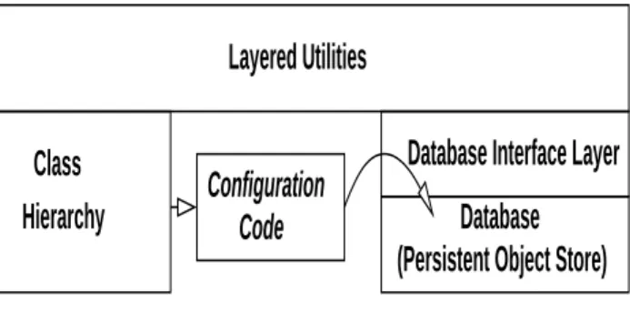
The classes contain attributes and methods that when in-stantiated allow for linkages to be created that describe the network topology, or topologies, of the cluster in a way that can be leveraged by the Layered Utilities described in Section 5. The objects contained in the database are data-structures. These data-structures are defined both by the classes in the Class Hierarchy and to some extent by how they are instantiated. Upon instantiation the objects are stored in the database to later be referenced by the Lay-ered Utilities. Since the stored objects are utilized based on the same Class Hierarchy that the objects were instantiated from, the database becomes the basis of portability for all upper-level utilities. The only thing that changes from clus-ter to clusclus-ter is the database (how the Class Hierarchy is instantiated). The only code that is not re-used in the soft-ware architecture, if cluster network topology and/or device types change, is the code necessary to populate the database (see Figure 2).
While the actual generation of the database is the most challenging step from the user’s point of view, it is a nec-essary characteristic of the software architecture. Assump-tions about future network topologies should not be made by a software architecture. Separation and isolation of this
Hierarchy
Database Interface Layer
Database
(Persistent Object Store)
Configuration
Code
Layered Utilities
Class
Figure 2. Persistent Object Store Generation
characteristic is very important to portability. On the posi-tive side, clusters exhibit many similarities. With every new cluster implementation new examples to assist in later im-plementations are available to be used as templates. In prac-tice, large amounts of code re-use exist in creation of the Persistent Object Store. Additionally, this process is only performed once during the installation phase. From here on any manipulation of the database is generally performed by the layered tools (see Section 5).
Upon instantiation, objects contain information germane to their role in the cluster. The user is not required to use all capabilities that are defined in the class when they instanti-ate an object. During implementation it is up to the user to decide what attribute information is necessary to represent devices in their cluster but it should be noted that capabili-ties that require this information would not be functional if they are omitted. The user also has the flexibility to decide later to add supported capabilities to the instantiated object by using the layered tools described in Section 5. This ca-pability also lessens the challenge of creating the original configuration code to produce the database.
The use of an object’s attributes is best described by example. Take for instance a node object of class DS10. The full class path for this object is Device::Node::Alpha::DS10 (Figure 1). This object has access to the class attributes and methods of all of the classes in the entire class path. Following inheritance rules the attributes and methods are searched for in a reverse path sequence until found in the class. Note that if appropriate, methods can be overridden at any level in the class path.
The network interface(s) of devices are particularly im-portant in describing the network topology of the cluster. Interfaces are important for all devices in a cluster and therefore are defined as an attribute in the Device class. This interface attribute is used to describe the network topology of the node. It contains important information like the ad-dress or adad-dresses of a node, the corresponding netmask of the network, and the hardware address of the interface(s). This information is also important in the automatic genera-tion of configuragenera-tion files like hosts, configuragenera-tion files for
the initialization of network interfaces, and dhcpd.conf files for nodes that support diskless clients.
Another important piece of topology information for a cluster is the serial interface information, the console at-tribute. This is a case where linkage with other objects is de-scribed in the database. A terminal server device can supply access to the serial interface of a node. This terminal server device is another object that has been instantiated and stored in the database with its own attribute information, including interface information that describes its place in the network topology of the cluster. The console attribute, for our exam-ple node, references the terminal server device that supplies the serial or console interface. It also contains other impor-tant information that is provided upon access to the terminal server device such as to which port of the terminal server the node is connected. When we wish to access the console of our example node we extract the information contained in its console attribute. We then look up the referenced ob-ject, which is a terminal server device. The terminal server device has its own attribute information, topology and oth-erwise, that tells us how to reach it in the network topology. We continue to look up other attributes and objects in a re-cursive manner, as necessary, until we have constructed a complete path that will enable us to access the console of our example node.
Another important attribute of our example node is how its power can be controlled remotely. This example illus-trates how an attribute can reference a completely separate physical device, like an external power controller, but also an alternate identity of the same device. Recall from the previous discussion in Section 3 that physical devices can have alternate identities or dual purposes. In our example our device is of class DS10, which provides attributes and methods appropriate for a device of type Node. Since this physical device is also capable of power control via its serial interface, what we specify for the power attribute of our example is in the physical sense the same device. In our database, however, it is a completely different object of a different class, Device::Power::DS10 as opposed to Device::Node::Alpha::DS10 (Figure 1). The
Device::Power::DS10 object describes the
power capabilities of the device while the Device::Node::Alpha::DS10 object instantiates the node capabilities of the device. The console attribute of both the Device::Node::Alpha::DS10 object and the Device::Power::DS10 object specify the same console attribute (which is a terminal server object).
It is useful for devices, particularly nodes, to support multiple simple informational attributes, which can be leveraged by higher-level tools. The Device::Node::Alpha::DS10 object in our example per-forms as a computational node. We can utilize the attribute role in the Node class to persistently define the role as
”compute” and use it where appropriate in upper-level tools. Other typical values for the role attribute include ”service” and ”leader.” (The value ”leader” should not be confused with the attribute leader below.)
Several informational attributes like leader are contained in our example object, inherited from the super-class of Device. The leader attribute can be leveraged to produce a ”responsibility” hierarchy for portions of the cluster. A leader is defined as a device that is responsible for another device. Again, as with other attributes, a responsibility path can be recursively determined by extracting the leader at-tribute successively while traversing backwards to the de-sired point in the cluster hardware hierarchy. For all prac-tical purposes, a cluster has at least one leader. For large clusters it is advantageous to architect a cluster in a hierar-chical fashion for purposes of efficiency and scalability (see Section 6).
Other informational attributes include: image, sysarch, and vmname. The image attribute allows the user to spec-ify the boot image (kernel) on a per-node basis, while the sysarch attribute provides similar capability in selecting the root file system for a diskless node or the location to obtain a disk image for a diskfull node. The vmname attribute can be used to partition the cluster into smaller virtual machines, especially useful from the runtime perspective. Runtime initialization scripts can readily leverage this information to obtain configuration information. As we have shown, dif-ferent attributes are used to enable difdif-ferent functionalities in upper-level utilities.
All information necessary to describe both the physical structure and operation of the cluster is contained in the database. The interface to this database is implemented in a single layer, which lends itself to ease of replacement if an alternate underlying database is desired (see Figure 2 and 3). All calls to store information, extract, search, replace, or any other database interaction necessary are defined in this layer. Simply changing this layer and providing the defined base functionality allows for storing the objects in a differ-ent database of the user’s choice. This allows the Persistdiffer-ent Object Store to be implemented in virtually any database, with no changes to the Layered Utilities, or the Class Hier-archy. As we will show in Section 5 the Layered Utilities get all the information they need to perform their required capability from the Persistent Object Store and Class Hier-archy.
5. Layered Utilities (Cluster Management
Tools)
The term ”Layered Utilities” is used to describe a wide range of capabilities that are made possible by leverag-ing the Class Hierarchy and the Persistent Object Store (database). One category of these utilities is tools that allow
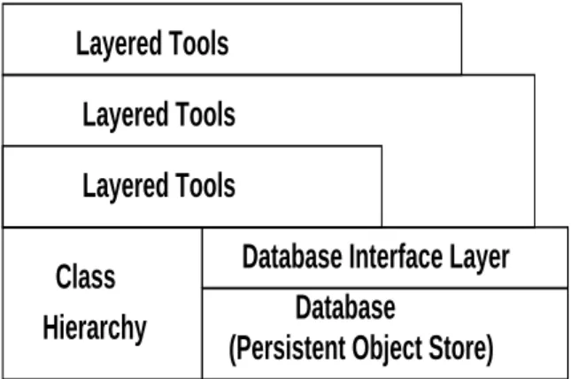
extraction, modification, or addition of information in the database. By using the capabilities provided by the classes in the Class Hierarchy these tools become easy to imple-ment. See Figure 3 for a graphical representation of the software architecture and Layered Utilities.
(Persistent Object Store)
Database
Hierarchy
Layered Tools
Layered Tools
Layered Tools
Database Interface Layer
Class
Figure 3. Layered Utilities
An example for purposes of illustration is the capability to extract, change or set the IP address of a node. As with virtually all cluster management tools, the get/set IP ad-dress tool is layered on top of the Database Interface Layer (Figure 2 and 3), which provides the interface to the Per-sistent Object Store. This tool interfaces with the database through the Database Interface Layer to extract the object by name. Access to the object’s attributes and methods is provided by the Class Hierarchy based on the class the ob-ject was instantiated from. We use the class methods to extract the information that we require, in this case the IP address of the device. If we are changing the IP address, we simply modify the existing information or IP address in the object we fetched, and store the modified object back into the database. To demonstrate some of the flexibility of this approach, consider that this utility requires no changes between cluster implementations. It simply leverages a ca-pability that is defined in the Class Hierarchy, which also requires no changes when implemented on another cluster (provided the cluster is constructed of devices defined in the existing Class Hierarchy), and the Database Interface Layer, which also ports unchanged.
Foundational capabilities are important and common among cluster implementations. Some examples of these are the capabilities to power cycle or boot a node in a cluster. Powering other devices in the cluster is also essential. All information needed to implement these capabilities is con-tained in the database. For example, to control the power of a device a tool need only extract the object that describes the device, access the power attribute of that device, and if nec-essary recursively follow the network management topol-ogy chain to obtain all the information necessary to
per-form the operation. Likewise, if the desired operation were, ”send a boot command to a node,” the tool that performs this function would extract the appropriate object from the database. Then, assuming we need to issue a boot com-mand on the console, access the console attribute of the de-vice and (recursively, if necessary) determine the path to that console, connect and deliver the command. If the node boots with a wake-on-lan signal, the tool would recognize this based on the object and simply call an external wake-on-lan program to issue the appropriate signal on the correct network.
The purpose of layering these tools is higher-level tools can leverage lower-level tools, which further abstracts core capabilities. The lower-level capabilities can be modified or enhanced without affecting the upper-level tools as long as the interface remains consistent. Multiple high-level tools can leverage these lower-level tools. Additionally, as higher levels of capability are achieved, it may be required to in-clude cluster specific information to achieve the required functionality. Since portability is one of the important goals of this effort, using a layered approach maximizes the prob-ability that the lower-level tools will port easily. Exposure and isolation of any site or cluster specific code or config-uration information is most appropriate at the highest level if customization is required. Isolation of these properties also allows the largest amount of code to be portable from implementation to implementation.
An example of a site or cluster specific quality that is purposely not dictated by this software architecture is the naming scheme chosen for the devices. By naming scheme we are referring to the names associated with the physical devices in the cluster. The objects that represent the devices in the cluster are stored in the database, and are referenced by these names. This software architecture allows for a site or cluster specific naming convention to be chosen by the user. This information is isolated from the tools so that a minimal amount of work is required to use an alternate nam-ing scheme from the one already provided. This isolation is implemented and used by the highest-level tools. No depen-dency by lower layers of tools exists. Another related ex-ample, site-specific command line parsing and sorting rou-tines are abstracted out and isolated into their own module. These command line parsing routines allow the tools that leverage them to port without modification. The functional-ity of these tools is retained while allowing a site to choose their command line options. This also provides a method of generic command line parsing, presenting a common look and feel to the users of the high-level layered tools. Great care has been taken to localize any characteristic like these to enhance portability.
6. Scalability
Traditional approaches to cluster management often sup-port only a small number of nodes, and operate on those nodes individually. One concept that can be leveraged from our software architecture, for both organization and scala-bility purposes, is the concept of ”collections.” Collections are an abstraction or grouping of entries in the database. Collections can contain any combination of devices or addi-tional collections. This means that devices do not have to be dealt with individually but can be controlled as groups that can be arbitrarily defined in the database. One such organi-zational practice is to group all devices in a rack into a col-lection; another would be to create a collection of compute nodes grouped in either a physically or logically meaningful way. Devices or collections are not limited to membership in a single collection. Any number of collections can be es-tablished for any reason and leveraged by our layered tools. Among many cluster management efforts it is also com-mon to perform tasks serially. This approach can suffice for small clusters but even short duration operations performed in a serial manner can quickly add up to long execution times. Consider a simple command that takes an average of 5 seconds to execute. On a 64 node cluster, that com-mand would take 320 seconds (5.33 minutes). That same short duration command would take 5120 seconds (85.33 minutes) on a cluster of 1024 nodes. It is easy to see that serial operations are not efficient or scalable on even mod-erate size clusters.
For the purposes of scalability, our layered tools act on collections as a unit, if appropriate, to achieve a level of par-allelism. If a higher level of parallelism can be achieved by grouping devices in a different manner, a different collec-tion can be established in the database and then acted on as a unit to perform scalable parallel operations. Depending on the purpose of the layered tool, parallelism can be in-serted at any or all levels of operation. A tool can launch an operation on several collections in parallel. The operation within the collection may be performed in serial, thus the duration of the entire operation will be the length of time the operation takes on a single collection. If the time of ex-ecution is considered too long, further parallelism can be applied within the collection, shortening the execution time even further.
Not only can the layered tools exploit collections to im-prove scalability, they can also operate based on groupings formed by the aforementioned leader attribute. Groups can be dynamically generated by associating devices with the node designated in the leader attribute of the object. Par-allel operations can then achieve scalability by execution on these leader-generated groups. Again, parallelism can be applied across these leader-groups or additionally within them. The leader concept becomes increasingly valuable as
cluster node counts increase.
Creating cluster hardware architectures in a hierarchical manner which groups nodes with leaders physically, allows for clusters to scale even further by enabling work to be of-floaded to these leaders for execution. Our software archi-tecture supports this multi-level hardware archiarchi-tecture and leverages it to operate most optimally. A cluster’s architec-ture is a major factor in its potential scalability. Although hardware architecture is not the focus of this paper, it is im-portant to note how the software architecture supports key architecture decisions. Clusters can be built in many topolo-gies from flat to hierarchical. Our software architecture is topology agnostic, but built with large-scale cluster systems in mind. Previously discussed characteristics like device types and collections, and attributes like leader and role, all can be used to leverage hierarchical topologies, which we believe have more potential to scale to the desired node counts (thousands of nodes). No limitation on the number of levels in the hardware architecture is imposed by our ap-proach. It is our contention that to achieve scalability on the order of thousands of nodes, both the hardware architecture and the software architecture that supports it must be hier-archical in nature. For example, to perform an operation on many devices the leaders of the target devices could be de-termined and the desired operation could then be offloaded to them. This of course can all be done as a parallel opera-tion.
Since so many aspects of the software architecture are dependent on the Persistent Object Store (database) it fol-lows that the database must support any required level of parallel operations. Different clusters, largely based on size, will impose different requirements on the underlying database. The abstraction and consolidation of the database layer allows for substitution of the actual database layer that stores the device objects without modification of the re-mainder of the software architecture. When a more scalable underlying database is necessary to support the cluster, the database layer can be replaced to provide the interface to the new database, and the cluster tools port unaltered. For ex-ample, Lightweight Directory Access Protocol (LDAP)[10] provides a database that can be distributed. This eliminates having a single database image that is accessed by an in-creasing number of nodes as a cluster scales. LDAP also provides good parallel read characteristics, which account for the largest percentage of database accesses.
Commodity clusters, unlike more highly integrated sys-tems, can grow with time in a more unrestricted manner. Different support devices and heterogeneous nodes may be added to existing clusters. As these clusters scale with dif-ferent equipment, the interface presented to the user by our software architecture is virtually unchanged. Again, it is important to not attempt to guess how these systems will be architected in the future. A software architecture must
allow enough flexibility to not only support the wide range of current COTS cluster systems, but the cluster systems of tomorrow.
7. Future Work
At the time of this writing the implementation of these concepts has allowed us to build and support ten cluster systems with different devices and topologies. The largest of these systems is an 1861 node system that is completely diskless with the exception of the administration node at the top of the hardware hierarchy. Additional work on the top-ics presented here will include: support for a wider range of devices in the Class Hierarchy, support for alternative database layers, and addressing any aspects of the software architecture that are found to present problems in the areas of portability, extensibility, or inefficiencies in scaling. New capabilities in the form of tools to manage the clusters are constantly being added.
8. Discussion and Conclusion
This project was originated in support of the CplantTM project at Sandia National Laboratories. In an attempt to encourage further development and use of this work all soft-ware related to this project will be released as open source. In the implementation of this software architecture on our clusters we have leveraged open source software wherever possible. The entire implementation of the architecture pre-sented in this paper was written in Perl[11]. Perl modules obtained from CPAN[12] were leveraged whenever possi-ble.
One of our guiding design principles was to make as few assumptions as possible about how other sites will build clusters and how they will manage them. At each stage in the design of the Class Hierarchy and low-level tools in particular, great care was taken to keep things as generic as possible. So far this approach has paid off. The largest sin-gle disadvantage of our approach to cluster management is the difficulty of initial database configuration. Generally, it takes a few tries to get it right and the (often monolithic) configuration program could be a bit daunting to a first time user. However, once the database is instantiated, all the other tools based on it ”just work” and there is no need to customize them even for a wide variety of hardware and topologies.
9. Acknowledgments
The CplantTM project at Sandia involves many people from many different organizations, all of whom have con-tributed to the overall success of this project. In particu-lar, the authors would like to acknowledge the contributions
of the Scalable Systems Integration department, Scalable Computing Systems department, and the Scientific Com-puting Department. In particular, we acknowledge Mike Levenhagen for his work on the initial CplantTMcluster man-agement tools and for his ideas that were leveraged by this architecture.
References
[1] R. B. Brightwell, L. A. Fisk, D. S. Greenberg, T. B. Hudson, M. J. Levenhagen, A. B. Maccabe, and R. E. Riesen. Mas-sively Parallel Computing Using Commodity Components.
Parallel Computing, 26(2-3):243–266, February 2000.
[2] Chiba City, Argonne National Laboratory, 9700 S. Cass Avenue, Argonne, IL 60439. http://www-unix.mcs.anl.gov/chiba/
[3] VA Software Corporation, 47071 Bayside Parkway Fremont, CA 94538 http://www.vasoftware.com
[4] Intel, 2200 Mission College Blvd., P.O. Box 58119 Santa Clara, CA 95052-8119 http://www.intel.com
[5] TurboLinux, 8000 Marina Blvd, Suite 300, Brisbane, CA 94005. http://www.turbolinux.com
[6] Compaq Computer Corporation, P.O.
Box 692000 Houston, Texas 77269-2000 http://www.compaq.com/solutions/customsystems/hps/linux-cmu.html
[7] Scyld Computing Corporation, 410 Severn Ave., Suite 210 Annapolis MD 21403 http://www.scyld.com/
[8] NPACI Rocks, San Diego Supercomputer Center Univer-sity of California San Diego La Jolla, CA 92093-0505 http://rocks.npaci.edu/index.php
[9] Linux Networx, 8689 South 700 West Sandy, UT 84070 http://www.linuxnetworx.com/products/clusterworx.php [10] Lightweight Directory Access Protocol community
devel-oped LDAP software http://www.openldap.org [11] http://www.perl.org