A Software Engineering Environment
for Developing Web Applications in .Net
A M I R T A L A E I – K H O E I
Master of Science Thesis Stockholm, Sweden, 2007 ICT/ECS-2007-134
Master of Science Thesis
AMIR TALAEI-KHOEI
Supervised by Prof. Claude Petitpierre (EPFL/IC/ISIM/LTI) Examined by: A/Prof. Vladimir Vlassov (KTH/ICT/ECS)
i
Abstract
Web applications are ubiquitous on the Internet, and almost every type of business now needs to be able to quickly develop their own applications, but as web applications become more complex, developers look for more systematic ways to build quality applications with minimum effort.
This thesis proposes an environment that focuses on generating the first draft of a web application for an architectural-based system model design. Since the description is high level, it’s easy to produce and it only needs the basic knowledge of web application development, additionally because the chosen architecture is very close to the way that the most of web applications are developed the generated code is still easy to change in .Net platform.
iii
Acknowledgment
I’m extremely grateful for kind consideration of a person, who guided me during the whole project, from its very beginning to the end; Olivier Buchwalder, a PhD student at LTI. He made me interested in the topic, and helped me a lot with theoretical issues, as well as with problems that arose during the implementation.
v TABLE OF CONTENTS ABSTRACT ... I 1 CHAPTER 1: INTRODUCTION ... 1 1.1 PROBLEM STATEMENT ... 2 1.2 GOALS ... 2 1.3 BRIEF DESCRIPTION ... 2 1.3.1 Roadmap of Work ... 3 1.3.2 Limitations ... 4 1.4 THESIS OUTLINES ... 4 2 CHAPTER 2: BACKGROUND ... 7
2.1 MODEL DRIVEN DEVELOPMENT (MDD) ... 7
2.1.1 Modeling Rationale and MDD ... 8
2.2 MODEL DRIVEN ARCHITECTURE (MDA) ... 12
2.3 SOFTWARE FACTORY ... 14
2.3.2 Software Factory Templates ... 16
2.3.3 Systematic Reuse ... 17
2.4 DOMAIN SPECIFIC MODELING AND LANGUAGE (DSM&DSL) ... 17
2.4.1 Basic Concepts ... 18
2.4.2 Migration from Abstract to Real and from Meta to Instance ... 19
2.5 COMPARISON OF MDA AND SF ... 21
2.6 MICROSOFT VISUAL STUDIO DSLTOOLS ... 22
2.6.1 Building a Designer using Microsoft DSL Tools ... 23
2.7 RELATED WORKS ... 26
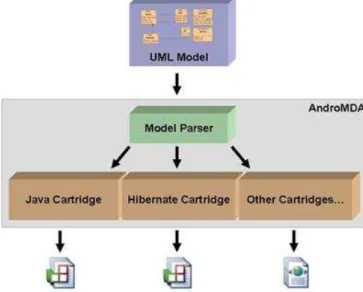
2.7.1 AndroMDA (Bhatia 2006) ... 26
2.7.2 Web Relational Blocks ( WebRB ) ... 27
2.7.3 WebLang ... 29 2.8 STATE OF ART ... 31 2.9 SUMMARIZING TERMS ... 31 3 CHAPTER 3: METHODS ... 33 3.1 EASYWEB ... 33 3.1.1 Requirements ... 33 3.2 DSLDEVELOPMENT METHODOLOGY ... 35 3.2.1 Analysis... 36 3.2.2 Implementation ... 36 3.2.3 Test ... 37
vi
3.3.1 Microsoft DSL Tools: Worthy to Catch on? ... 39
3.4 EASYWEB GRAPHICAL DESIGNER ... 39
3.5 EASYWEB PROGRAMMING EDITOR ... 41
4 CHAPTER 4: IMPLEMENTATION ... 43
4.1 LANGUAGES ... 43
4.1.1 Domain Model for Web Applications ... 43
4.1.2 Intermediate Language ... 44
4.1.3 Modeling Language ... 45
4.1.4 Simple Example ... 46
4.2 IMPLEMENTATION OF GRAPHICAL DESIGNER ... 48
4.2.1 Domain modeling in Microsoft DSL Tools ... 48
4.2.2 Implementation of DSL+ ... 49
4.2.3 Implementation of Template Generator ... 49
4.3 IMPLEMENTATION OF PROGRAMMING EDITOR ... 51
4.4 IMPLEMENTATION OF INTERPRETER ... 53
4.4.1 Structure ... 53
4.4.2 Overview of Datatypes and Generated Codes ... 53
5 CHAPTER 5: ANALYSIS ... 55
5.1 VALIDATION ... 55
5.2 EVALUATION METHOD ... 56
5.2.1 Using as a Requirement Engineering tool ... 56
5.2.2 Computational Model ... 56
5.2.3 Technological Model Independency ... 56
5.2.4 Graphical Designer ... 57
5.2.5 Quality of Generated Codes ... 57
6 CHAPTER 6: CASE STUDY: COURSE MANAGEMENT SYSTEM ... 59
6.1 BRIEF DESCRIPTION OF SYSTEM REQUIREMENTS ... 59
6.2 DESIGNING ... 60
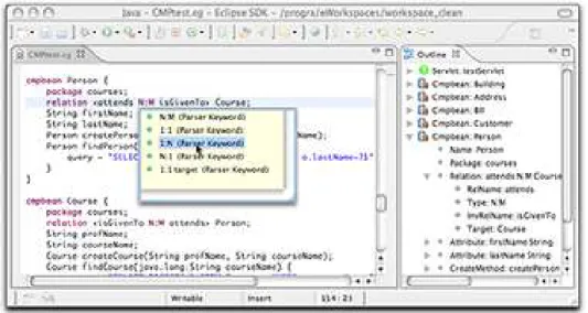
6.2.1 Designing with Programming Editor ... 60
6.2.2 Designing with Graphical Designer ... 64
7 CHAPTER 7: CONCLUSION ... 69 7.1 SUMMARY OF CONTRIBUTIONS ... 69 7.2 FUTURE WORKS ... 69 BIBLIOGRAPHY ... 71 APPENDIX A ... 75 APPENDIX B ... 87
vii
INDEX OF FIGURES
FIGURE 1.ROLES FOR DEVELOPING WEB APPLICATION USING EASYWEB... 3
FIGURE 2.ROADMAP FOR DEVELOPING IN EASYWEB ... 4
FIGURE 3.DIFFERENT WAYS OF SYNCHRONIZATION OF CODE AND MODEL (BROWN 2004) ... 9
FIGURE 4.SEQUENCE OF MDD (H.N.PHAM 2007)... 11
FIGURE 5.PROCESS MODEL OF MDA(BROWN 2004) ... 13
FIGURE 6.SOFTWARE FACTORY (GREENFIELD 2007) ... 15
FIGURE 7.REUSABILITY OF SOFTWARE FACTORY (GREENFIELD 2007) ... 17
FIGURE 8.MODEL MIGRATION (KOVARI 2004) ... 19
FIGURE 9.AMICROSOFT VISUAL STUDIO GRAPHICAL DESIGNER, BUILT BY DSLTOOLS ... 23
FIGURE 10.WHERE MICROSOFT DSL TOOLS SEAT... 24
FIGURE 11.MICROSOFT VISUAL STUDIO MODELING PLATFORM ... 25
FIGURE 12.TEMPLATE BASED CODE GENERATION ... 25
FIGURE 13.ILLUSTRATION DIAGRAM FOR ROADMAP ... 26
FIGURE 14.ANDROMDAARCHITECTURE (BHATIA 2006) ... 27
FIGURE 15.WEBRB:BLOCKS AND WIRES (J.RAYFIELD 2007) ... 28
FIGURE 16.WEBLANG:WEBAPPLICATION DEVELOPMENT IDE (C.PETITPIERRE 2006) ... 29
FIGURE 17.HOW WEBLANG MAPPED J2EE COMPONENTS (C.PETITPIERRE 2006) ... 30
FIGURE 18.WEBLANG CODEGEN (O.BUCHWALDER 2006) ... 30
FIGURE 19.SCOPE OF EASYWEB ... 34
FIGURE 20.EASYWEB DETAIL REQUIREMENTS ... 35
FIGURE 21.CUSTOMARY ARCHITECTURE OF MICROSOFT DSLTOOLS ... 38
FIGURE 22.EASYWEB GRAPHICAL DESIGNER ARCHITECTURE ... 41
FIGURE 23.CONCEPTUAL DIAGRAM FOR LANGUAGES USED IN EASYWEB ... 44
FIGURE 24.ASIMPLE WEB APPLICATION ... 46
FIGURE 25.ABSTRACT MODEL OF SIMPLE EXAMPLE ... 47
FIGURE 26.SYSTEM MODEL IN PROGRAMMING EDITOR FOR A SIMPLE EXAMPLE ... 47
FIGURE 27.INTERMEDIATE CODE FOR SIMPLE EXAMPLE ... 48
FIGURE 28.DOMAIN MODELING IN MICROSOFT DSLTOOLS FOR EASYWEB ... 49
FIGURE 29.ADIALOG FOR SELECTING A .TT FILE TO GENERATE TEMPLATE INSIDE... 50
FIGURE 30.CHOOSING MODE FOR GENERATING TEMPLATE ... 50
FIGURE 31.EASYWEB GRAPHICAL DESIGNER ... 51
FIGURE 32.DEFINITION OF APPLICATION THAT IT CONSISTS OF DATABASES AND WEBPAGES ... 52
FIGURE 33.METHODS GENERATED FOR MODULE APPLICATION IN CODEGEN ... 52
FIGURE 34.MDDSAVING AND BENEFITS (SIEGEL 2005) ... 56
FIGURE 35.COURSE MANAGEMENT SCENARIO ... 59
viii
FIGURE 37.WEBPAGE DESIGN IN PROGRAMMING EDITOR ... 61
FIGURE 38.SKELETON OF BUSINESS LOGIC IN PROGRAMMING EDITOR ... 62
FIGURE 39.DEFINING OPERATIONS IN PROGRAMMING EDITOR ... 63
FIGURE 40.DEFINING INITIALIZATION IN PROGRAMMING EDITOR ... 63
FIGURE 41.DESIGNING OUTPUT IN PROGRAMMING EDITOR ... 64
FIGURE 42.SPECIFYING THE APPLICATION NAME AND THE SERVER ... 65
FIGURE 43.SPECIFYING TABLES IN GRAPHICAL EDITOR ... 65
FIGURE 44.DEFINING WEBPAGES IN GRAPHICAL DESIGNER ... 66
FIGURE 45.SKELETON OF BUSINESS LOGIC DESIGN IN GRAPHICAL DESIGNER ... 66
FIGURE 46.DESIGN GETLIST OPERATION ... 67
FIGURE 47.INITIALIZATION OF COURSEPAGE:COURSEPAGEINI ... 68
FIGURE 48.CREATING THE PROJECT ... 76
FIGURE 49.SELECTING DOMAIN SPECIFIC LANGUAGE OPTIONS ... 77
FIGURE 50.DEFINING NEW MODEL FILE TYPE ... 77
FIGURE 51.SPECIFY PRODUCT DETAILS... 78
FIGURE 52.DESIGNER DIAGRAM (JAMES 2007) ... 78
FIGURE 53.CUSTOM DESIGNER (JAMES 2007) ... 79
ix
INDEX OF TABLES
TABLE 1.KEYWORDS IN INTERMEDIATE LANGUAGE ... 44 TABLE 2.KEYWORDS OF MODELING LANGUAGE ... 45
x
1
Chapter 1
1 Introduction
As Web applications grow in size, the size of development projects grows as well, and it becomes more and more critical to support modular application design and parallel development. The challenge lies in meeting a few unique requirements.
The most important requirement to be met is that the solution supports the appropriate division of the development effort into smaller and different kinds of tasks that can be performed by various kinds of developers, such as architects, screen designers, and business logic programmers. It must then support the efficient integration of the many outputs from these different tasks. There must also be a cost-effective method of unit and integration testing if we are to maximize the parallel progress of the tasks that are inherently dependent upon one other.
Most of the technology is here to implement systems that exploit the web paradigm, but the effective design of Web applications is still a concern. The complexity and requirements on web applications are constantly growing, while the supporting technologies and platforms rapidly evolve.
Web applications are quite common now, though the development and specially requirement analysis phase of them are still a big challenge. Such a situation is attributable to the flood of technologies and lack of standards.
At the time, most of web application developers and companies involved in this industry need some facilities to rapid prototyping and tools for easy design web application not only in case of interface but also for developing a web applications with all links, operations in a speedy architectural design, actually considering amount of strong tools in interface deign for web applications the point of interface is doesn’t matter for developers specially when they want to make a prototype and deliver it to customer as soon as possible.
In this work I have tried to present a tool for developing the first draft web application or prototype which can be used by persons who has basic knowledge about web applications and how they can be developed. In this case if we can find a person with this amount of knowledge in the customer side which is not really far from of imagination, the tool can be counted as a user development environment which is important in the recent aspects of software engineering to find the requirements as better as possible.
EasyWeb, the tool that I am going to release can help .Net developers to make their own web application just with architecture design which is possible in graphical user friendly designer or programming editor with the user assist abilities. In this work I have tried and make much more efforts on simplicity to generate web application easily and rapidly with architectural design.
1.1 Problem Statement
When you are using .Net environment to develop web applications, you have a very strong IDE to design your web pages and coding inside with another strong programming language (ASP.Net), but actually which is needed for rapid first draft development and also needed for designing web application is an environment that you can have an architectural design and then generate the application.
.Net Environment with a lot of facilities and components needs an expert programmer to use and develop applications but unfortunately we can see the opposite in reality that most of time designers know the basics but they are not expert in programming. Therefore EasyWeb has been developed for designers to design the system architecture and then they can generate executable end user application, however this one is not deliverable to market but it can show the functionality and structure.
1.2 Goals
EasyWeb as a tool for developing web application has been goaled for developing first draft web application coded in ASP.Net and not goaled for developing ready market application or interface design because as we have described in pervious section we have already strong tools and IDE such as .Net to do these kinds of stuffs.
To sum up the goals for EasyWeb tool is speeding up the following items in the web application development life cycle:
• Developing the first draft of web applications • Clarifying the architecture
• Justification the operations
This Tool has to be made developer friendly environment for rapid development however it doesn’t need to consider about the interface design.
The scenario has been designed for developing web applications using this tool for requirement engineering and especially for prototyping then using .Net IDE for release the market ready version of end application. Figure 1 shows this life cycle or scenario which is proposed for developing web applications, for the first draft, designer uses EasyWeb for simple architectural design which can generate executable code for web application, this version is also useful for clarifying the architecture.
1.3 Brief Description
As far as we said in pervious sections, I’m going to have a tool for simplification of web application development in .Net with architectural design. EasyWeb as my tool and which I will
propose in this work tries to provide a graphical designer and also a programming environment with user assistance ability for developing these kinds of application.
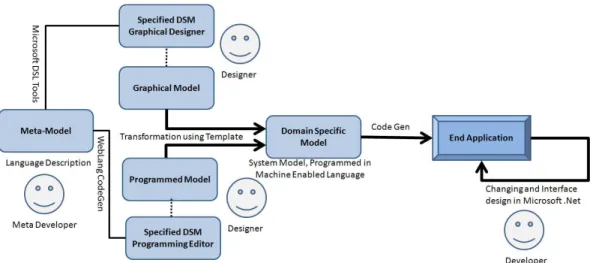
Figure 1. Roles for developing web application using EasyWeb 1.3.1 Roadmap of Work
Figure 2 tries to show the roadmap of this work for developing EasyWeb. In this work we have described a language consists of datatypes and their properties for describing a web application and using this language developer can model their systems in two different environments:
• A Graphical Designer: meta developer (in this case I am) using the Microsoft DSL tools defined a language which is used for modeling systems and run the Microsoft DSL Tools, then the result was a Microsoft VS Designer for developing web applications, this environment has some drag and drop facilities for describing entities of mentioned application and also it has some wizards for determining properties of these entities. In designer tool I have tried to make some facilities for simplification of properties determination.
• A Programming Editor: EasyWeb has also a programming completion-enabled editor for modeling systems with programming. In this case I have used a tool developed in LTI1 to define the different language (but with the same concepts of pervious one) in graphical editor and also produced an editor. Designers can model their systems in this editor simply and then after compilation, it will be transformed to language designed in Microsoft DSL Tools.
So both graphical and programmed model produced by designer should be transformed to a machine enabled language and then Code Gen will be used for generating executable codes for end application. EasyWeb Code Gen read the machine enabled program and then generate .aspx and .cs files, which are executable and then it is also possible to change in Microsoft .Net Environment.
1
Lab. Teleinformatique located at Department of Computer and Communication Sciences, EPFL, Switzerland and where WebLang has been also developed. You can find its web site on ltiwww.epfl.ch
Figure 2. Roadmap for Developing in EasyWeb 1.3.2 Limitations
As far as I have to use Microsoft DSL Tools and WebLang CodeGen tool I will face to some limitations that these tools force:
• Microsoft DSL Tools: Microsoft DSL Tools are designed to develop product line and not executable end application and actually for developing end application. We also need some properties which should be advised and manage by some wizard to make their specification more easily than just entering some properties. But architecture of these tools however allows defining properties but it’s hard to generate some wizard for getting data.
• WebLang CodeGen: WebLang doesn’t allow us to generate graphical designer so to generate this kind of designer for who think it’s easier, we should use Microsoft DSL Tools however I believe programming environments are much easier and more efficient.
1.4 Thesis Outlines
The rest of the report has been organized as follows:
• Chapter 2, Background: It gives the reader brief explanation of Model Driven Development and its approaches, and then it explains the much more details in Software Factory as a used concept in EasyWeb. It also has a introduction on Microsoft DSL Tools and WebLang as tools that I have used in this work.
• Chapter 3, Methods: This chapter presents the usecases and design of EasyWeb, it also covers the architecture of this tool.
• Chapter 4, Implementation: All Design methods need implementation to create the tool, this chapter is specified for explaining my implementation and how I have actually created EasyWeb.
• Chapter 5, Analysis: Firstly, it discusses about how our roadmap and activities to achieve a Domain Specific Language is valid, and then it covers the evaluation of EasyWeb and its compression to other tools in this area.
• Chapter 6, Case Study: This chapter explains a simple web application has been developed with EasyWeb. Chapter can also be used as a tutorial of EasyWeb.
• Chapter 7, Conclusion: This chapter sums up the all I have achieved in this project and also it clarifies directions have been opened in my works.
• Some Appendices: During the report we have pointed to some information that it can be read only as a reference so I have put them at the end of the report. Please consider that references are presented in Chicago Style. Therefore the name of author and year inside of the parentheses mean a reference which can be found in biography part of report.
7
Chapter 2
2 Background
This chapter covers the theory of Model Driven Development (MDD) that readers need to know for understanding my work. In following sections, we will have an overview on Model Driven Development and its strategies; Model Driven Architecture and Software Factory, then we will focus on Domain Specific Language, its Microsoft DSL Tools and we will also explain WebLang.
2.1
Model Driven Development (MDD)
In recent years many organizations have begun to focus attention on Model Driven Development (MDD) as an approach to application design and implementation. This is a very positive development for several reasons. This approach encourages efficient use of system models in the software development process, and it supports reuse of best practices when creating families of systems.
As Pham said, “Since the introduction of high-level programming languages like C, C++ and Java, software developers have seen a big breakthrough in productivity. Instead of having to construct their applications from primitives like load, store and
jump, developers are able to express their logic using higher and more natural programming constructs like loops, conditionals, etc., and then call upon a compiler to generate (virtual) machine-level code. Also, using these languages, the task of porting software to a new execution platform when it comes along involves only a recompile, as opposed to a rewrite or a redesign, of the programs in the system. These benefits came from the basic idea that, by raising the abstraction level of the language used by developers, and by automating the process of transforming code from the raised abstraction level to the target (lower) abstraction level, productivity in both software development and maintenance can be significantly improved” (H. N. Pham 2007). MDD is a software engineering methodology with particular focus on models, automation and code generation. The difference to traditional software development is that MDD proposes to leverage models to generate the specified software system. Two currently dominant approaches to MDD are Model-Driven Architecture (MDA) (J. Mukerji 2003) and Software Factories (SF) (J. Greenfield 2004).
The concept of model-driven development (MDD) is really starting to catch on because of its promise to increase the productivity of those charged with the task of developing and maintaining application systems. But what exactly is MDD?
MDD is a development practice where high-level, agile, and iterative software models are created and evolved as software design and implementation takes place. The key defining characteristic of MDD is that the model literally becomes part of the development process. Contrast this with an approach such as the waterfall development process where modeling appears as a separate step in the process and tends to get left behind once the development proceeds to the next phase (Schwaderer 2006).
Models are used to specify software systems, but unfortunately these models mostly serve only for the purpose of documentation and comprehending the system. Changing this fact by using these existent models to generate the application, software development can easily be automated. By automatic code generation, the quality of an application can be increased, due to the fact that code is produced according to a certain structure, scheme or rules. In this way the generated code will precisely match the models. Further on this road the evolution could lead to the fact that modeling languages replace the implementation languages, just like the way third-generation languages replaced the assembly languages through the introduction of compilers (Demir 07).
2.1.1 Modeling Rationale and MDD
Referring to oxford dictionary;” Model is a simplified mathematical description of a system or process, used to assist calculations and predictions” and Fishery Glossary says “Models help to show relationships between processes (physical, economic or social) and may be used to predict the effects of changes in land use” and it also defines Modeling as “The construction of physical, conceptual or mathematical simulations of the real world”.
The concept of the model and the modeling in the IT area is focusing. In this field a model represents a part of reality (target) which was specified by a modeling view and described by modeling facilities in order to the purposes for recognition, understanding, and manipulation of the target.
A model is a form of abstraction that allows real-world entities to be represented in a simplified manner, so that they can be dealt with in safer, cheaper and easier ways (Rothenberg 1989).
Finally, by IBM definition; Models provide abstractions of a physical system that allow engineers to reason about that system by ignoring extraneous details while focusing on relevant ones. All forms of engineering rely on models to understand complex, real-world systems. Models are used in many ways: to predict system qualities, reason about specific properties when aspects of the system are changed, and communicate key system characteristics to various stakeholders. The models may be developed as a precursor to implementing the physical system, or they may be derived from an existing system or a system in development as an aid to understanding its behavior (Brown 2004).
In the software engineering world, modeling has a rich tradition of programming. The most recent innovations have focused on notations and tools that allow users to express system perspectives of value to software architects and developers in ways that are readily mapped into the programming language code that can be compiled for a particular operating system platform. The current state of this practice employs the
Unified Modeling Language (UML) as the primary modeling notation. The UML allows development teams to capture a variety of important characteristics of a system in corresponding models. Transformations among these models are primarily manual. UML modeling tools typically support requirements traceability and dependency relationships among modeling elements, with supporting documents and complementary consulting offerings providing best practice guidance on how to maintain synchronized models as part of a large-scale development effort (Brown 2004).
Figure 3. Different ways of synchronization of code and model (Brown 2004)
Code Only: Today, a majority of software developers still take this approach and do not use separately defined models at all. They rely almost entirely on the code they write, and they express their model of the system they are building directly in a third-generation programming language such as Java, C++, or C# within an Integrated Development Environment (IDE) such as Visual Studio .Net. Any "modeling" they do is in the form of programming abstractions embedded in the code (e.g., packages, modules, interfaces, etc.), which are managed through mechanisms such as program libraries and object hierarchies. Any separate modeling of architectural designs is informal and intuitive, and lives on whiteboards, in PowerPoint slides, or in the developers' heads. While this approach may be adequate for individuals and very small teams, it makes it difficult to understand key characteristics of the system among the details of the implementation of the business logic. Furthermore, it becomes much more difficult to manage the evolution of these solutions as their scale and complexity increases, as the system evolves over time, or when the original members of the design team are not directly accessible to the team maintaining the system (Brown 2004).
Code Visualization: As developers create or analyze an application, they often want to visualize the code through some graphical notation that aids their understanding of the code's structure or behavior. It may also be possible to manipulate the graphical notation as an alternative to editing the text-based code, so that the visual rendering becomes a direct representation of the code. Such rendering is sometimes called a code model, or an implementation model (although many feel it is appropriate to call these artifacts "diagrams" and reserve the use of "model" for higher levels of abstraction). In tools that allow such diagrams (e.g., IBM WebSphere Studio and Borland Together/J), the code view and the model view can be displayed simultaneously; as the developer manipulates either view, the other is immediately synchronized with it. In this approach, the
diagrams are tightly coupled representations of the code and provide an alternative way to view and possibly edit at the code level (Brown 2004).
Roundtrip Engineering (RTE): This approach is a functionality of software development tools that provides generation of models from source code and generation of source code from models; this way, existing source code can be converted into a model, be subjected to software engineering methods and then be converted back. Round-trip engineering encompasses two engineering practices, forward engineering and reverse engineering. And what are these? In short, they are terms that represent a relationship between diagrams and code. The idea of Roundtrip Engineering is closely related to reverse engineering. Reverse engineering can be defined as the process of reconstructing the design of a product from the product itself. Assume that there is a reverse engineering procedure that is always able to give the design of a given product. Now assume that there is a procedure that will always generate the product from a given design. If a design is reverse engineered from a product, used to generate a product and the generated product is identical to the original product then this is a roundtrip engineering system (A. Henriksson 2003).
Model Centric: In this approach, the system models have sufficient detail to enable the generation of a full system implementation from the models themselves. To achieve this, the models may include, for example, representations of the persistent and non-persistent data, business logic, and presentation elements. If there is any integration with legacy data and services, the interfaces to those elements may also need to be modeled. The code generation process may then apply a series of patterns to transform the models to code, frequently allowing the developer some choice in the patterns that are applied (e.g., among various deployment topologies). This approach frequently makes use of standard or proprietary application frameworks and runtime services that ease the code generation task by constraining the styles of applications that can be generated. Hence, tools using this approach typically specialize in the generation of particular styles of applications (e.g., IBM Rational Rose Technical Developer for real-time embedded systems and IBM Rational Rapid developer for enterprise IT systems). However, in all cases the models are the primary artifact created and manipulated by developers (Brown 2004).
A model-only: In this approach developers use models purely as aids to understanding the business or solution domain, or for analyzing the architecture of a proposed solution. Models are frequently used as the basis for discussion, communication, and analysis among teams within a single organization, or across multi-organizational projects. These models frequently appear in proposals for new work, or adorn the walls of offices and cubes in software labs as a way to promote understanding of some complex domain of interest, and to establish a shared vocabulary and set of concepts among disparate teams. In practice, the implementation of a system, whether from scratch or as an update to an existing solution, may be disconnected from the models. An interesting example of this is the growing number of organizations that outsource implementation and maintenance of their systems while maintaining control of the overall enterprise architecture (Brown 2004).
There is a significant question, which explores that which of these approaches is adapted by MDD; unfortunately none there isn’t an exact answer, it could be some
things same as Model Centric approach but it should generate code directly and automatically from a visualized model.
What exactly do you mean by "visualize" a model? It's basically to graphically represent code syntax and code concepts or domain concepts and structures. A picture is worth a thousand words. It's much better to see a UML diagram with a bunch of boxes with lines connecting them than to try and read through source code. Domain visualization is basically going beyond the code to model more abstract concepts, such as 'what is a customer,' 'what is a purchase order' and 'what is an address.' The idea is to come up with a domain-specific language. This is a specialized notation that enables you to have the business analyst communicate in a very intuitive fashion. For instance, you wouldn't use UML to prove a calculus theorem; you would use the domain-specific language of calculus.
The model should be platform independent, which basically decouples you from underlying technology and buffers you from changes in the technology. And it allows you to redeploy on different technology, like the ability to deploy onto Java or .Net. Then you bind that platform independent representation to a specific technology and you create a platform-specific model such as .Net.
From a MDA perspective, it all is about creating usable models that allow you to know about your code assets because it's very easy to inventory and visualize them. And then you can extend those assets through creating inheritance and derived models.
Model-Driven Development is a software engineering approach that aims to push this idea one step further. It proposes a software development methodology in which software is developed not by writing code directly in implementation languages, but by constructing high level models that can be transformed into code by automated transformation engines and code generators, as illustrated in Figure 3 below (H. N. Pham 2007).
Figure 4. Sequence of MDD (H. N. Pham 2007)
As you can see in the diagram, firstly, we have to figure out a model from our system which should be visualized by business analysis and then generate the program which will be compiled and produce the machine executable code.
2.1.1.1 Benefits of MDD
Following the concept of high level programming languages; we can point on three benefits of MDD (H. N. Pham 2007):
• Easier software specification, understanding, and development: high-level modeling concepts, as compared to those found in implementation languages, are much closer to the real concepts in the problem domain, so we could have much easier development.
• The ability to generate any where: since the concepts used in the models are less bound to the underlying implementation technology, software is less susceptible to technological change. This makes software maintenance easier and more economical.
• Reusable: since expert implementation knowledge is encoded into the transformer, it can easily be reused and shared between different projects and teams, increasing both the productivity and quality of software development.
2.1.1.2 MDD’s Approaches
Two MDD’s approaches are the Model Driven Architecture (MDA) by the Object Management Group (OMG), and the Software Factories framework (SF) by Microsoft Corporation. Both of these methodologies call for the treatment of models as the primary artifacts – as opposed to an overhead that consumes development resources – in the software development process. They differ however, on how general (or specific) those artifacts should be, and how they are to be transformed to produce the actual implementation of the system (H. N. Pham 2007).
MDA proposes to apply the Unified-Modeling Language (UML). Due to aspects like platform independence and reusability, the software system is supposed to be modeled in three major steps, described further down. SF, as proposed by Microsoft, is an entire software development paradigm, which makes use of Domain Specific Modeling (DSM) (DSM Publication 2007).
2.2 Model Driven Architecture (MDA)
Referring the idea that models are vital and necessary to handle complexity in software development, Model-Driven Architecture (MDA) specifies a process for creating models.
As Brown Said “There are many views and opinions about what MDA is and is not. However, the most authoritative view is provided by the Object Management Group (OMG). Why does the OMG's view of MDA matter so greatly? As an emerging architectural standard, MDA falls into a long tradition of OMG support and codification of numerous computing standards over the past two decades. The OMG has been responsible for the development of some of the industry's best-known and most influential standards for system specification and interoperation, including the Common Object Request Broker Architecture (CORBA), OMG Interface Definition Language (IDL), Internet Inter-ORB Protocol (IIOP), Unified Modeling Language (UML), Meta Object Facility (MOF), XML Metadata Interchange (XMI), Common Warehouse Model (CWM), and Object Management Architecture (OMA). In addition, OMG has enhanced these specifications to support specific industries such as healthcare, manufacturing, telecommunications, and others (Brown 2004).”
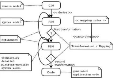
As a glance on Processes of MDA in Figure 5 we can understand that three principles underlie the OMG's view of MDA (Brown 2004):
• Computation Independent Model (CIM): Models expressed in a well-defined notation are a cornerstone to understanding systems for enterprise-scale solutions.
• Platform Independent Model (PIM): The building of systems can be organized around a set of models by imposing a series of transformations between models, organized into an architectural framework of layers and transformations.
• Platform Specific Model (PSM): A formal underpinning for describing models in a set of meta-models facilitates meaningful integration and transformation among models, and is the basis for automation through tools.
Figure 5. Process Model of MDA (Brown 2004)
Three ideas are important here with regard to the abstract nature of a model and the detailed implementation it represents (Brown 2004):
• Model classification: We can classify software and system models in terms of how explicitly they represent aspects of the platforms being targeted. In all software and system development there are important constraints implied by the choice of languages, hardware, network topology, communications protocols and infrastructure, and so on. Each of these can be considered elements of a solution "platform." An MDA approach helps us to focus on what is essential to the business aspects of a solution being designed, separate from the details of that "platform."
• Platform independence: The notion of a "platform" is rather complex and highly context dependent. For example, in some situations the platform may be the operating system and associated utilities; in some situations it may be a technology infrastructure represented by a well-defined programming model such as J2EE or .Net; in other situations it is a particular instance of a hardware topology. In any case, it is more important to think in terms of what models at different levels of abstraction are used for what different purposes, rather than to be distracted with defining the "platform."
• Model transformation and refinement: By thinking of software and system development as a set of model refinements, the transformations between models become first class elements of the development process. This is important because a great deal of work takes places in defining these transformations,
often requiring specialized knowledge of the business domain, the technologies being used for implementation, or both. We can improve the efficiency and quality of systems by capturing these transformations explicitly and reusing them consistently across solutions. If the different abstract models are well-defined, we can use standard transformations. For example, between design models expressed in UML and implementations in J2EE, we can, in many cases, use well-understood UML-to-J2EE transformation patterns that can be consistently applied, validated, and automated.
2.3 Software Factory
Increasingly complex and rapidly changing requirements and technologies are making development increasingly difficult. Promising advances have been made, however, in component based and model driven architecture, software architecture, aspect oriented programming, and requirements, process and software product line engineering. We will present Software Factories, a paradigm for automating software development that integrates these advances to increase agility, productivity, and predictability across the software life cycle. We will show a worked example of a software factory and perform small group exercises that help participants explore this approach. Participants will learn about the software factory schema, a graph of viewpoints used to separate concerns, relating work done at one level of abstraction, in one part of a system, or in one phase of the life cycle, to work done at other levels, or in other parts and phases, and about how the schema can be used to deliver guidance and to support its enactment through model transformation, constraint checking and other techniques. We will also describe the software factory life cycle and show how software factories can be specialized and composed. Finally, we will discuss software supply chains and show how Software Factories compose across organizational boundaries.
Microsoft introduces Software Factories (SF) as a new software development paradigm. SF primarily focuses on product Line Development, which copes with developing a set of similar but distinct products. In this context SF relies heavily on models and automation, which are basic concerns of MDD. This paper will focus on the MDD concerned aspects of SF (Demir 07).
A Software Factory is a Software Product Line that configures extensible tools, processes, and content using a software factory template based in a software factory schema to automate the development and maintenance of variants of an archetypical product by adapting, assembling, and configuring framework based components [3]. A Software Factory has two central elements, a Software Factory Schema and a Software Factory Template. A SF Schema defines, categorizes and summarizes the artifacts and assets required to build a software product line. It can be seen as a recipe listing ingredients, tools and the application process. A SF Template is based on the SF Schema and represents the implementation of the SF Schema that means that all defined assets and artifacts have to be built and made available. The implementation comprises among others developing DSLs. The SF Template can be seen as a bag of groceries containing the ingredients listed in the recipe (SF Schema) (Demir 07).
2.3.1.1 Software Factory Schema (Greenfield 2007)
A software factory schema is a document that categorizes and summarizes the artifacts used to build and maintain a system, such as XML documents, models, configuration files, build scripts, source code files, SQL files, localization files, deployment manifests and test case definitions, in an orderly way, and that defines relationships between them, so that we can maintain consistency among them.
A software factory schema is represented as a directed graph whose nodes are viewpoints and whose edges are computable relationships between viewpoints called mappings. This allows nodes that would not be adjacent in a grid representation to be related. Also, it relaxes the artificial constraint imposed by a grid that the viewpoints must fit into neat classification schemes, creating rows and columns. Finally, and most importantly, it allows the schema to reflect the software architecture. So, for example, a schema for a family of business applications might contain several clusters of viewpoints, one for each subsystem like customer management, catalog management, or order fulfillment. The viewpoints in each cluster might then be further grouped into subsets reflecting the layered architecture of each subsystem, as illustrated in Figure 6.
Figure 6. Software Factory (Greenfield 2007)
A software factory schema describes the artifacts that comprise a software product, just as an XML schema describes the elements and attributes that comprise a document, and a database schema describes the rows and columns that comprise a database. Like an Architectural Description Standard (ADS), a software factory schema is a template for describing the members of a software product family. Despite this similarity, however, there are several major differences between a software factory schema and ADS: While an ADS deals only with architecture, a software factory schema deals with many other aspects of a software product family, such as requirements, executables, source code, test harnesses and deployment artifacts. While an ADS organizes design documentation, a software factory schema organizes development artifacts.
While an AD implies a software product family, it does not explicitly identify one, or incorporate mechanisms to support family based development, such as a way to express how the members of the family differ from a family archetype. A software factory
schema, on the other hand, targets a specific software product family and can be instantiated and customized to describe a specific family member in terms of its differences from the family archetype.
While an ADS does not necessarily support automation, a software factory schema can be implemented by a software factory template to automate software development tasks, as we shall see shortly.
Of course, the essential property of a software factory schema is that it provides a multi dimensional separation of concerns based on various aspects of the artifacts being organized, such as their level of abstraction, position within architecture, functionality or operational qualities. According to Coplien (Coplien 1999):
We can analyze the application domain using principles of commonality and variation to divide it into sub domains, each of which may be suitable for design under a specific paradigm.
We can now see the grid as a two dimensional projection of the graph that plots one or more aspects on the horizontal axis and different levels of abstraction on the vertical axis. Another two-dimensional projection is an aspect plane, which projects related viewpoints onto part of the product architecture, providing a consolidated view from that viewpoint. Examples of aspects planes include logical data, security policy and transaction planes.
A software factory schema essentially defines a recipe for building members of a software product family. Clearly, the viewpoints describe the ingredients and the tools used to prepare them, but where is the process of preparing them described? Recall that a process framework is constructed by attaching a micro process to each viewpoint, describing the development of conforming views, and by defining constraints like preconditions that must be satisfied before a view is produced, post conditions that must be satisfied after it is produced, and invariants that must hold when the views have stabilized. This framework defines the space of possible processes that could emerge, depending on the needs and circumstances of a given project. Clearly, there is a resemblance between a process framework and a software factory schema. The viewpoints of a software factory schema already define micro processes for producing the artifacts they describe. Adding constraints to a software factory schema to govern the order of execution makes it a process framework, as well. We now have a recipe for the members of a product family. It defines the ingredients, the tools used to prepare them and the process of preparing them.
2.3.2 Software Factory Templates (Greenfield 2007)
As Greenfield said “If all we have is the software factory schema, then we can describe the assets used to build family members, but we do not actually have the assets. Before we can build any family members, we must implement the software factory schema, defining the DSLs, patterns, frameworks and tools it describes, packaging them, and making them available to product developers. Collectively, these assets form a software factory template.
A software factory template includes code and metadata that can be loaded into extensible tools, like an Interactive Development Environment (IDE), or an enterprise life cycle tool suite, to automate the development and maintenance of family members.
We call it a software factory template because it configures the tools to produce a specific type of software, just as a document template loaded into a tool like Microsoft Word or Excel configures it to produce of a specific type of document.”
2.3.3 Systematic Reuse (Greenfield 2007)
One of the most important innovations in software development is defining a family of software products, whose members vary, while sharing many common features. A family provides a context in which problems common to the family members can be solved collectively. This enables a more systematic approach to reuse, by letting us identify and differentiate between features that remain more or less constant over multiple products and those that vary. A software product family may consist of either components or whole products.
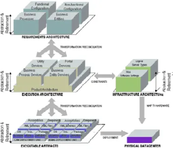
Software product lines exploit product families, identifying common the features and recurring forms of variation in specific domains to make the production of family members faster, cheaper, and less risky. Products developed as family members reuse requirements, architectures, frameworks, components, tests and many other assets. Figure 7 describes the key tasks performed and artifacts produced and consumed in a product line. Product line developers build production assets applied by product developers to produce family members in much the same way that platform developers build device drivers and operating systems used by application developers. A key step in developing the production assets is to produce one or more domain models that describe the common features of problems in domains addressed by the product line, and the recurring forms of variation. These models collectively define the scope of the product line, are used to qualify prospective family members. Requirements for family members are derived from them, providing a way to map variations in requirements to variations in architecture, implementation, executables, development process, project environment, and many other parts of the software life cycle.
Figure 7. Reusability of Software Factory (Greenfield 2007)
2.4 Domain Specific Modeling and Language (DSM & DSL)
We are not interested in using the general purposed languages (GPL) (Garwick 1968) because, GPLs, compared with DSLs, use a vocabulary that is simple and basic enough
to describe any domain without the specifics. The same level of expression and understanding of a domain is possible using GPLs, but the expected level of knowledge regarding the domain and the general language is considerably higher compared to a DSL approach. A major advantage of a DSL is that it requires significantly less time to understand and to communicate details of a domain. It also requires less time to learn to use the pertinent tooling (Kovari 2004).
For example, business applications are often implemented using complex software solutions, but most of the solutions use the same building blocks (patterns) to deliver business functions. A DSL enables you to abstract the software solution and hide the implementation details. A DSL can also use the vocabulary from the business domain and provide the translation for the IT domain.
We are also not interested in models rendered by hand on white boards, or on note pads. We are interested in models that can be processed by tools, and we propose to use them in the same way that we currently use source code. Models used in this way cannot be written in languages designed for documentation. They must be precise and unambiguous. In order to raise the level of abstraction, a modeling language must therefore target a narrower domain than a general purpose programming language. We find that the Unified Modeling Language (UML), in particular, is suitable for sketching, but not for the capture of high fidelity metadata used to generate models, code and other software development artifacts. A detailed discussion of the issues around using UML as language for MDD is beyond the scope of this article, but Cook provides a cogent analysis, and Fowler adds several insights on his blog page.
A language that meets these criteria is called a Domain Specific Language (DSL), because it models concepts found in a specific domain. A DSL is defined with much greater rigor than a general purpose modeling language. Like a programming language, it may have either textual or graphical notation.
A core principle of the SF approach is to enable a high degree of reuse of existing assets and development of new reusable assets. The development of a specific member of a product family comprises reusing existing assets and developing variable assets for that specific member. The SF approach uses the concept of Domain-Specific Modeling (DSM), which utilizes Domain-Specific Languages (DSLs) for modeling (Demir 07).
2.4.1 Basic Concepts
In the scope of engineering we have two approaches:
Generic approach: providing the general solution for many problems in a certain area (A. V. Deursen 2000).
Specific approach: searching for specific solutions in smaller area (A. V. Deursen 2000).
It’s clear that when we want to be more general we should cover much more points, instances, cases and even exceptions so absolutely our solution is hard to be optimal but when we are in specific concept we can be more optimal than the pervious approach. Currently, we can have three approaches in solving problems in a well-defined application domain:
Subroutine libraries contain subroutines that perform related tasks in well-defined domains like, for instance, differential equations, graphics, user-interfaces and databases. The subroutine library is the classical method for packaging reusable domain-knowledge (A. V. Deursen 2000).
Object-oriented frameworks and component frameworks continue the idea of subroutine libraries. Classical libraries have a flat structure, and the application invokes the library. In object-oriented frameworks it is often the case that the framework is in control, and invokes methods provided by the application-specific code (A. V. Deursen 2000), (R. E. Johnson 1988), (M. E. Fayad 1997) .
Domain Specific Languages are small, usually declarative, languages that offer expressive power focused on a particular problem domain. In many cases, DSL programs are translated to calls to a common subroutine library and the DSL can be viewed as a means to hide the details of that library (A. V. Deursen 2000).
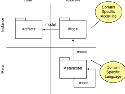
2.4.2 Migration from Abstract to Real and from Meta to Instance
As you can see in Figure 8, first of all we should define a meta and abstract language to develop a model that the language is called Domain Specific Language (DSL) and the model is Domain Specific Model (DSM).
DSL: A domain-specific language is a programming language or executable specification language that offers, through appropriate notations and abstractions, expressive power focused on, and usually restricted to, a particular problem domain (A. V. Deursen 2000).
Figure 8. Model Migration (Kovari 2004)
For advantages of DSL we can name (M. E. Fayad 1997):
• DSLs allow solutions to be expressed in the idiom and at the level of abstraction of the problem domain. Consequently, domain experts themselves can
understand, validate, modify, and often even develop DSL programs (M. E. Fayad 1997).
• DSL programs are concise, self-documenting to a large extent, and can be reused for different purposes (D. A. Ladd 1994).
• DSLs enhance productivity, reliability, maintainability (M. E. Fayad 1997), (E. K. A. V. Deursen 1998), (R. B. Kieburtz 1996) and portability (R. M. Herndon 1988).
• DSLs embody domain knowledge, and thus enable the conservation and reuse of this knowledge (M. E. Fayad 1997).
• DSLs allow validation and optimization at the domain level (A. Basu 1997), (Bruce 1998), (V. Menon 1999).
• DSLs improve testability following approaches such as (E. G. Sirer 1999). Its disadvantages are (M. E. Fayad 1997):
• The costs of designing, implementing and maintaining a DSL.
• The costs of education for DSL users.
• The limited availability of DSLs (Krueger 1992).
• The difficulty of finding the proper scope for a DSL.
• The potential loss of efficiency when compared with hand-coded software engineering
Modeling with DSL and UML are at the opposite ends of the spectrum, in some respects. UML is a unified (or general) modeling language; it can support literally any model. DSM is a domain specific modeling language. It can only support specific types of models (M. E. Fayad 1997). Considering the concept of DSL and UML we can mark the DSL as more practical approach than UML and absolutely when you use UML you can reach the Model Centric Approach or maybe also roundtrip but as far as you see DSL tries to visualize the concept with code generation including some aspects of business logics.
DSM (Kovari 2004): In engineering sciences like IT, experts use models, diagrams, and sketches to describe specific details of a problem or a solution. The need for visual representation arises from the high degree of complexity surrounding the industry. Abstraction and automation justify the need for visual modeling.
Engineers in IT work with various inputs, outputs, work products, and deliverables. One output may become the input for another work product. Models and diagrams are often part of or are the actual work products. The flow of information, the reuse of previous results, and the automation of the workflow justify the use of models over simple diagrams.
Figure 2 shows the most basic approach for building an application for modeling, modeling itself, and producing various artifacts from the models in domain specific areas.
According Figure 2, starting from the meta-model, the developer has to establish the meta-model or language for the specific domain. Constraints can enrich the meta-model to ensure the semantic correctness and validation of the model instances. Most of the graphical editor can be generated from the meta-model, but other parts have to be manually defined. A new set of constraints can be specified for the graphical editor because the graphical representation may use different constructs for modeling than the original meta-model. Model instances can be created and edited using the graphical editor. These models are the results of model-driven development. Models become the input to transformations to generate the final artifacts (code, for example).
2.5 Comparison of MDA and SF
(Demir 07)
As Demir Said “The MDA solution shows that productivity can be increased by applying the MDA approach. Certainly, the utilized tool plays an important role, but a better productivity can be achieved particularly due to the omission of the implementation phase. A disadvantage in this case is that the learning phase for the MDA tool is due to its complexity and individuality very time-consuming. Nevertheless, the modeling process can be started immediately, since the modeling language (UML) is already provided, apart from the fact that specific UML Profiles are needed and not granted by the MDA tool.
The SF solution shows that the SF methodology can increase productivity as well, basically for the same reason as in the case of MDA, the implementation part is omitted. But, before reaching this point, the expense for the SF approach is much higher, because the DSL has to be developed first, which is time-consuming and sophisticated, and requires expert knowledge about the problem and the solution domain. This fact delays the start of the modeling process.
Once a DSL is created, a better efficiency can be achieved, because a DSL comprises domain concepts and thus it is closer to the problem domain. This fact facilitates involving business stake holders into the specification process to avoid misinterpretation and confusion. This is an advantage for DSLs, since the comprehension of UML models require UML experts.
Quality and reliability of a software system can be improved as well in both approaches, particularly due to the reason that the generated code is less error prone, because of its generation according to a scheme, rules or code-templates. Provided that the model interpreter works properly, the generated code is more reliable than handcrafted code that usually contains bugs, because a developer tends to make mistakes. Furthermore, the generated applications exactly meet their specification in form of models, since they are generated according to them.
Certainly, MDA and SF apply similar methods and techniques for modeling and mapping, but they have distinct objectives. Due to the high expense of developing a DSL and a code generator, the SF approach is only recommendable for developing Product Lines, because this expense has to be compensated somehow. However, once a DSL and the code generator are developed, the costs for generating the product line
members are very low due to their similarity. The overall costs of a product line development can then be distributed on the amount of all members, which makes the SF approach productive. Otherwise, for One-Off development, the SF approach would be expensive in terms of time, budget and resources. MDA on the contrary can be used for One-Off Development and Product Line development, since there is no additional expense to compensate. Product Line development with the MDA approach would even increase the regular expected degree of productivity, because the first model could be reused for the other product line members.
Fact is that MDA is a pure MDD approach and focuses on platform independence, while SF is an entire software development methodology and focuses on product line development. UML as the standard modeling language for MDA is a general purpose language, which has to be specialized and constrained with Profiles to be appropriate for MDD. A DSL in contrary is supposed to be developed for a specific domain from beginning, without specializing and constraining afterwards, in this manner DSLs can be very efficient within that domain, but also very useless in other domains.
On the whole, both approaches have their strengths and weaknesses; none of them is clearly in advance. Depending on the purpose they are applied for, they demonstrate different strengths and weaknesses. An appropriate problem domain, professional developers, a suitable tool and a precise idea of the intended products or product family, can guarantee each approach’s benefits.”
2.6 Microsoft Visual Studio DSL Tools
Domain-Specific Language Tools allow Visual Studio 2005 developers to create their own graphical designers and code generation tools like the ones you find in Visual Studio today, such as the Class Designer.
You can use Domain-Specific Language Tools to generate visual designers that are customized for your problem domain. For example, you can create a tool to describe concepts that are specific to how your organization models business processes. If you are building a state chart tool, you can describe what a state is, what properties a state has, what kinds of states exist, how transitions between states are defined, and so on. A state chart that describes the status of contracts in an insurance company is superficially similar to a state chart that describes user interaction among pages on a Web site. However, their underlying concepts differ significantly. By creating your own domain-specific language and custom generated designer, you can specify exactly what state chart concepts you need in your tool (Domain-Specific Language Tools 2007).
DSL Tools takes a graphical approach to DSL construction. When you start a new DSL project what you are provided with is a DSL Designer that allows you to create a “diagram editor” in the form of a generated VS Designer. This might seem confusing because what you have is a Designer of Designer which you use to create a custom Designer which the end user then uses to create a diagram and generate code. It begins to make more sense when you start to make use of it, but it helps to realize that you first use the DSL Designer to specify the type of diagram the user can create – a flow chart, class diagram, workflow diagram – essentially any collection of boxes and arrows subject to the rules that you specify for how they can be arranged to create a diagram (James 2007).
Once you have used the DSL Designer to specify your custom designer you use the standard templates to generate code which you then run. The generated code creates your custom designer which you can run in VS. It has a toolbox full of the entities you specified and you can use it to create an instance of the type of diagram you specified (James 2007).
2.6.1 Building a Designer using Microsoft DSL Tools
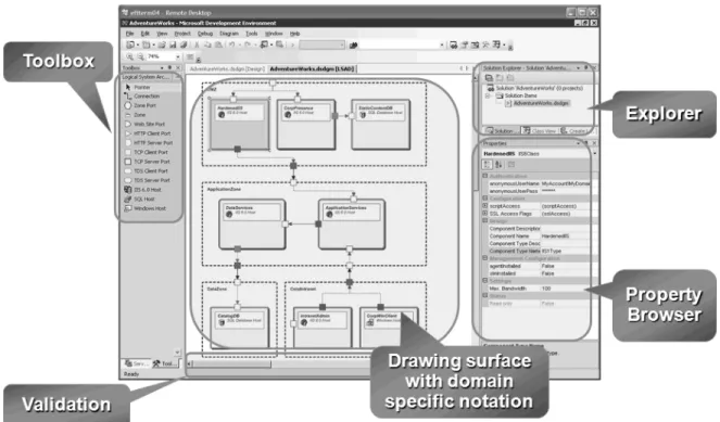
The goal of this activity is developing an environment such as one shows in Figure 9, to enable developer for modeling his/her system and then generated directly the code.
Figure 9. A Microsoft Visual Studio Graphical Designer, built by DSL Tools
As you can see, we have following parts in these kinds of modeling environments:
Toolbox: as far as you may familiar with visual environments specially .Net’s ones for doing stuffs of modeling we may have some toolboxes which help us to develop and represent our intention and what are in our mind.
Drawing Surface: this part takes a place for your model and then the environment supposes that your model is entirely summarized in this place.
Property Browser: in this part the environment shows the defined properties of selected component in the drawing surface.
Explorer: explorer part of the environment can show and brow all components that you have defined in the drawing surface using toolbox.
Validation: to be sure about the validity of your model this is a tool helps you to check your model before generating codes.
After illustrating the goal, we can focus on the structure of Microsoft DSL Tools and where they are located. Fist of all, at the base of structure we can see modeling platform of VS which can generate all modeling platforms in Visual Studio, so to achieve our desired environment we should develop our libraries on this platform. What the DSL Tools can do for us is presenting an environment that we should use it for more high level work than using the modeling platform for itself. Figure 10, tries to clarify this concept.
As far as you can see in Figure 10, DSL tools are developed to produce new designer on the .Net framework using modeling platform libraries. In this case for defining your language with tools have been proposed in DSL and running the program we could have such an environment.
to four libraries and one engine as follows:
Figure 10. Where Microsoft DSL tools seat.
Figure 11 presents modeling platform structure and which parts it has. In this case we can divide this platform
Shell Framework: The Premier Partner Edition (PPE) provides a version of Visual Studio that includes the Visual Studio IDE, the debugger, and source code control integration. No programming languages are included. Although PPE does not include programming languages, PPE does provide a framework that lets you add programming languages (Microsoft 2005). This framework provides a core IDE for users to develop their own custom programming language or development tools, so it doesn't provide languages or compilers, or a lot of the content of Visual Studio and it will be available in two modes, integrated and isolated (Frye 2007).
Validation Framework: These libraries can be used for applying reusable and customizable rules to properties and methods to provide validation for your strongly typed business objects.
Domain Model Framework: These libraries consist of some non-accessible classed used for developing design surface libraries and template engine.
Design Surface Framework: These libraries use the domain model framework and build the graphical designer specified for your language.
Figure 11. Microsoft Visual Studio Modeling Platform
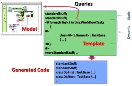
Template Engine: First of all, let us to explain what a template is? The templates can access the meta objects directly; properties of the meta objects can be used to provide data for template evaluation as shown in the pervious illustration, and then generate some codes. To generate the end application we should run a code like one is showed in Figure 12, which is divided in two types of code; the first one is more standard stuffs and the second one is model dependent stuffs. For more clear words we must call them the constant part and the dynamic part.
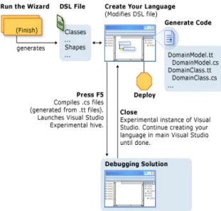
Figure 12. Template Based Code Generation
To sum up the Microsoft DSL Tools, you may consider the illustration diagram in Figure 13 which provides a high-level overview of how you can design, customize, test, and deploy a domain-specific language. As you can see in this figure, first of all we should define our language and with pressing the F5, you can see a graphical environment that designer can use it to model his/her system. Then with using template files (.tt files) you can read the model and then based on what you have read generate codes.