Tenor DX
VoIP MultiPath/Gateway
Switch
Product Guide
T
able of Contents
About this Guide
What’s included? . . . 1-2 Typographical Conventions . . . 1-3 Product Guide Conventions . . . 1-3 Finding Help. . . 1-4
Chapter 1: Overview
What is the Tenor DX? . . . 1-2 Features. . . 1-4 Unique Design . . . 1-4 State-of-the-Art GUI Configuration and Network Management . . . 1-4 SelectNet™ Technology Safety Net . . . 1-4 PacketSaver™ reduces bandwidth consumption . . . 1-5 Easy Connect to Console . . . 1-5 Powerful System Monitoring . . . 1-5 Capabilities . . . 1-6 Virtual Tie Line . . . 1-6 SNMP Support . . . 1-6 Call Detail Recording . . . 1-6 IVR/RADIUS Support . . . 1-6 NATAccess™. . . 1-7 Call Routing/Management Options . . . 1-8 Routing Table Options . . . 1-10 Call Management Features . . . 1-11 H.323 Gatekeeper Services. . . 1-12 Gatekeeper . . . 1-12 Zone Management . . . 1-12 Call Registration. . . 1-12 Border Element . . . 1-12 Call Services . . . 1-13 SIP User Agent . . . 1-15
Chapter 2: Hardware Components
Hardware Description . . . 2-2 Front Panel Connections and Reset Options. . . 2-2 Front Panel LEDs. . . 2-5
RJ-45 Cables . . . 2-7 DB-9 Serial RS-232 Cable . . . 2-11
Chapter 3: Installation
Installation . . . 3-2 Pre-Installation Guidelines . . . 3-2 Inspect Package Contents . . . 3-2 Rack Install . . . 3-3 Connection. . . 3-6 Connect to Line Interface - PBX . . . 3-6 Connect to Trunk Interface - PSTN . . . 3-7 Connect to Ethernet LAN . . . 3-8 Connect to PC Console . . . 3-9 Install Ground Safety Cable (if required) . . . 3-10 Power up the System. . . 3-11 Assign IP Address . . . 3-12 Change IP Address . . . 3-13 Load Software Upgrade . . . 3-15
Chapter 4: Getting Started: Tenor Configuration Manager/Tenor Monitor
Overview . . . 4-2 Tenor Configuration Manager . . . 4-3 Getting Started with Configuration . . . 4-3 Tenor Monitor . . . 4-4 Getting Started with Monitoring . . . 4-4
Chapter 5: Getting Started: Command Line Interface (CLI)
What is the Command Line Interface? . . . 5-2 Options. . . 5-2 Modes . . . 5-2 Navigation . . . 5-2 User Login IDs . . . 5-3 Access CLI. . . 5-3 Telnet Connection . . . 5-3 Serial Port Connection . . . 5-4 Configuration via CLI . . . 5-5
Change CDR Password . . . 6-5 Tenor DX Establishes Connection with CDR Server . . . 6-6 CDR Server Establishes Connection with Tenor DX. . . 6-6 CDR Output . . . 6-7 Sample Record for Standard and Extended CDR Format 0, 1, 100, 101 . . . 6-7 Sample Record for Extended Tenor DX CDR Format 3, 4, 103, 104: . . . 6-10
Chapter 7: System Alarms
Overview . . . 7-2 Monitor Alarms. . . 7-2 How to Read Alarms . . . 7-2 Valid Alarms . . . 7-4 View Alarms . . . 7-7 Display all Alarms . . . 7-7 Display Active Alarms . . . 7-7 Display Alarm History. . . 7-8
Chapter 8: Diagnostics/Maintenance
Before you Begin . . . 8-2 Monitor LEDs . . . 8-2 Diagnostics . . . 8-3 Common Symptoms/Problems . . . 8-3 Verify Unit Provisioning . . . 8-4 Ping Unit . . . 8-4 Monitoring . . . 8-5 Alarms . . . 8-5 General Maintenance . . . 8-5 Restore Factory Defaults . . . 8-5 Reset System. . . 8-5 Change Password . . . 8-5 Change Unit Date and Time . . . 8-6 If you need Additional Help . . . 8-7
Appendix A: Specifications/Approvals
INDEX
GLOSSARY
WARRANTY
What’s included?
This product guide is divided into chapters; each chapter describes a specific topic. The following chapters are included:
• About this Guide: Describes what is included in the Product Guide, including typographical conventions. • Chapter 1: Overview. Includes a general overview of the product, including a description of the Tenor
DX’s features and capabilities.
• Chapter 2: Hardware Components. Hardware description, including the front and rear panels, as well as LEDs and required cables.
• Chapter 3: Installation. Describes how to install the Tenor DX unit, including how to connect, power up and assign the IP address.
• Chapter 4: Getting Started: Tenor Configuration Manager/Tenor Monitor. This chapter tells you how to use the TenorConfiguration Manager and Tenor Monitor to configure/monitor the unit.
• Chapter 5: Getting Started: Command Line Interface (CLI). This chapter tells you how to access the CLI and execute commands. A description of each CLI mode is also included.
• Chapter 6: Call Detail Recording. Describes the Call Detail Recording (CDR) feature, including how to set up the CDR server and assign a password. In addition, instructions for reading CDR output are also included.
• Chapter 7: System Alarms. Describes how to monitor and view alarms via Command Line Interface (CLI). In addition, alarm definitions are also included.
• Chapter 8:Diagnostics/Maintenance. Describes how to troubleshoot and monitor the health of the sys-tem.
• Appendix A: Specifications/Approvals: A list of Tenor DX specifications and approvals. • Glossary
• Index
Typographical Conventions
Product Guide Conventions
Certain typographical conventions are used throughout this product guide. See below.
• All commands you enter via keystrokes appear in bold (e.g., Press Enter or Press Ctrl-I).
• All text commands you enter via Telnet session or command line typing appear in italics (e.g., type active).
• There are three types of special text that are designed to reveal supplemental information: Note, Warn-ing, and Caution. See below.
A NOTE provides additional, helpful information. This information may tell you how to do a certain task or just be a reminder for how-to’s given in previous sections. (i.e., For a list of valid commands at any time, type ?)
A WARNINGprovides information about how to avoid harming your VoIP equipment or other equip-ment (i.e., Do not stack more than 4 units together.)
A CAUTION provides information about how to avoid injury to yourself or to others (e.g., Do not install the equipment during a lightning storm).
Finding Help
Refer to the Product Guide for help. The Table of Contents and Index tells you where to find information eas-ily.
Extensive configuration help is available via the Tenor Configuraton Manager and Tenor Monitor online help systems or the Command Line Interface online help system. See Chapter 4: Getting Started: Tenor Configu-ration Manager/Tenor Monitor for more information.
C
hapter 1: Overview
This chapter gives you a general overview of the
Tenor DX
including feature descriptions and
capa-bilities. Specifically, the following topics are covered:
!
A description ofTenor DX
!
Features!
Capabilities!
Call Routing/Management OptionsWhat is the
Tenor DX?
The
Tenor DX
is a high-density VoIP (Voice over Internet Protocol) H.323/SIP switch that converts
voice, fax, and modem data on digital circuit switched trunks, and transmits it over the IP network.
The
Tenor DX
integrates a gateway, gatekeeper, border element, intelligent call routing, and
sup-ports H.323/SIP, and QoS all in one solution. The gateway converts circuit switched calls to VoIP
calls, the gatekeeper performs IP call routing functions, and the border element distributes the call
routing directories throughout the network.
With its MultiPath architecture, the
Tenor DX
can intelligently route calls between the PBX, the
PSTN, and the IP network to achieve the best combination of cost and quality. It can also route calls
over IP to reduce costs, and then transparently “hop off” to the PSTN, to reach off-net locations.
Figure 1-1
Tenor DXVoIP Switch
The
Tenor DX
is available in two configuration types:
•
MultiPath Switch
(intended for PBX and PSTN connectivity)
•
Gateway
(intended for VoIP and PSTN trunk port connectivity).
The
MultiPath Switch
is mainly intended for symmetrical multipath applications. The number of
VoIP channels is equal to half the number of PSTN channels.The
MultiPath Switch
configuration
enables connectivity between the customer equipment (i.e., PBX), PSTN and VoIP Network. The
Gateway
is mainly intended for trunking applications interfacing between the VoIP network and the
circuit switched network (PSTN). The number of VoIP channels equals the number of PSTN
chan-nels.
Whichever configuration you choose, the high performance unit provides two 10/100 BaseT
con-nections and one RS-232 serial console port connection. The unit also incorporates an intelligent
call routing engine which regulates system resources and configuration while coordinating all voice
traffic activity in the unit.
The
Tenor DX
may be managed by the
Tenor
Configuration Manager
and
Tenor Monitor
. Through
the
Configuration Manager
, you can configure all options, such as signaling data, trunk groups, dial
plans, and call routing numbers. An easy-to-use Java-based installation process enables you to an
install the manager and start configuring within minutes. Through the
Tenor Monitor
, you can
mon-itor the health of the system, including alarms, call detail records, etc. Both the
Configuration
Man-ager
and
Tenor Monitor
provide comprehensive on-line help systems that are available at your
fingertips.
POWER ALERT R E S E T 1 2 3 4 5 6 7 8 Line/Act 100 Line/Act 100LAN 1 LAN 2 CONSOLE D
I A G
The unit’s simple plug and play embedded system architecture brings VoIP technology to your
net-work without changing your existing telephony infrastructure. Your netnet-work stays as is, and the call
type is transparent to the user. This technology boasts superior voice quality without compromising
reliability.
The
Tenor DX
is available in the versions listed in Table 2-1.
Table 2-1
Tenor DX MultiPath Switch configurations
Table 2-2
Tenor DX Gateway configurations
Tenor Digital DX
MultiPath
Configurations
Spans Available
(RJ-45 port for T1/E1
connection)
VoIP Channels Supported
Usage
DX2008 2 8 VoIP connections T1/E1
DX2016 2 16 VoIP connections T1/E1
DX2024 2 24 VoIP connections T1
DX2030 2 30 VoIP connections E1
DX4048 4 48 VoIP connections 2 x T1
DX4060 4 60 VoIP connections 2 x E1
DX6120 6 120 VoIP connections T1/E1
DX8120 8 120 VoIP connections T1/E1
Tenor Digital DX
Gateway
Configurations
Spans Available
(RJ-45 port for T1/E1
connection)
VoIP Channels Supported
Usage
DX2048 2 48 VoIP connections 2 x T1
DX2060 2 60 VoIP connections 2 x E1
DX4096 4 96 VoIP connections 4 x T1
Features
The
Tenor DX
’s specific features are explained below.
Unique Design
Tenor DX
packs powerful VoIP features into one compact unit. The system’s embedded design
enables you to configure the unit directly without depending on another operating system; it can be
either placed on a table or mounted in a 19” rack.
With its MultiPath technology, the Tenor can be installed without upgrades to the existing voice or
data network. Tenor connects to the data network through a 10/100 Ethernet interface, and to the
enterprise and public voice network through multiple T1/E1 or PRI interfaces. In addition, with a
wide range of configurations available, it offers the flexibility for you to select a configuration that
best matches your needs.
State-of-the-Art GUI Configuration and Network Management
Once the unit is connected, the
Tenor Configuration Manager
makes configuring a
Tenor DX
easy.
Through the manager
,
you are able to set all configuration parameters, such as unit, signaling, and
call type features, as well as monitor the unit for alarms, and call information.
In addition, you can configure the unit via
Command Line Interface (CLI
). Through this simple
tel-net session, you can access all configuration options, including an online help system, built into the
CLI, which provides help for all features and functions. Just type
help
at any prompt, and data about
that field will be displayed.
SelectNet™ Technology Safety Net
Quality of service is virtually guaranteed.
Tenor DX
’s built-in patented SelectNet
™
Technology
provides a “safety net,” which virtually guarantees that each call going VoIP will not only be routed
successfully, but will deliver high voice quality.
SelectNet monitors the IP network performance for VoIP calls. If the performance characteristics
become unacceptable—according to the delay, jitter, and packet loss specifications you configure—
the
Tenor DX
will switch the call to the PSTN automatically and transparently. The Tenor
continu-ously monitors your data network for jitter, latency and packet loss, and transparently switches
cus-tomer calls to the PSTN when required.
PacketSaver
™
reduces bandwidth consumption
PacketSaver packet multiplexing technology reduces the amount of IP bandwidth required to
sup-port multiple calls flowing between two endpoints. PacketSaver minimizes bandwidth usage by
aggregating samples from multiple VoIP conversations and packing them into a larger IP packet
with a single IP header. The process removes the need to send a bulky IP header with individual
voice packets. As a result, it eliminates the transmission of redundant information.
.
Easy Connect to Console
Plugging a serial cable between the unit’s RS-232 port and your PC’s console port, will allow local
unit management. Through the console connection, you are able to assign an IP address. In addition,
if you are directly connected to the unit, you are able to configure the unit via
Command Line
Inter-face (CLI).
Powerful System Monitoring
There are many different ways to monitor the health of the unit, including LEDs and alarms. LEDs
appear on the front of the unit. The LEDs light up according to operations and alarms the system is
experiencing.
Through the
Tenor Monitor
(see
Chapter 4: Getting Started: Tenor Configuration Manager/TenorMoni-tor
) and the
Command Line Interface (CLI)
(see
Chapter 5: Getting Started: Command Line
Inter-face (CLI))
, you can view a list of active system alarms, as well as view an alarm history. Each alarm
indicates the unit’s operational status.
Conventional VoIP Transmission Sends Many Redundant Packet Headers
Tenor Tenor R POWER ALERT RESET 12345678 Line/Act 100 Line/Act 100 LAN 1 LAN 2 CONSOLE DIAG R POWER ALERT RESET 12345678 Line/Act 100 Line/Act 100 LAN 1 LAN 2 CONSOLE DIAG
Capabilities
Virtual Tie Line
Tenor DX
can emulate a tie trunk. It provides all of the functionality of a tie trunk, including the
con-siderable cost savings, but eliminates the need for a PBX trunk to be configured, or marked as a tie
trunk. A traditional tie trunk is a PBX-configured direct connection between two PBXs in separate
locations. The tie trunk bypasses the PSTN network.
Your PBX does not need any additional configuration.
Tenor DX
treats all the trunks the same
with-out compromising voice quality.
SNMP Support
The
Tenor DX
supports Simple Network Management Protocol (SNMP), the standard protocol used
to exchange network information between different types of networks.
Call Detail Recording
Through the Call Detail Record (CDR) feature, the
Tenor DX
generates a call record at the
comple-tion of each call, typically for accounting purposes. A CDR is a string of data that contains call
information such as call date and time, call duration, calling party, and called party.
Tenor DX
may
store Call Detail Records locally or they can be sent to a CDR server within the network. The CDR
contains sufficient information to capture billing data, which can be used to create billing reports
using third party billing software.
IVR/RADIUS Support
Interactive Voice Response (IVR) is a feature of the
Tenor DX
that enables you to offer services,
such as Pre-paid calling cards and Post-paid accounts, to your customers.
The Tenor uses the RADIUS (Remote Authentication Dial-In User Service), for authenticating and
authorizing user access to the VoIP network, including ANI Authentication (Types 1 and 2). The
RADIUS is a standard protocol which provides a series of standardized message formats for
trans-mitting and receiving dialed information, account data and authorization codes between the network
access gateway and the billing server.
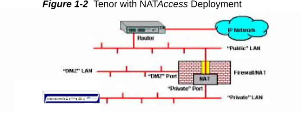
NAT
Access™
NAT
Access
is an intelligent network address translation technology. It enables VoIP networks with
multiple H.323 endpoints to operate behind firewalls equipped with H.323 Network Address
Trans-lation (NAT); this provides maximum network security. NAT
Access
simplifies deployment by
elim-inating the need to place the Tenor on a public IP network. Using NAT
Access
provides easy, secure
expansion between multiple VoIP sites. In addition, NAT technology in the Tenor permits the use of
private subnets at the same time; in-house calls will never go over the public internet.
Figure 1-2
Tenor with NAT
Access
Deployment
POWER ALERT RESET 12345678 Line/Act 100 Line/Act 100 LAN 1 LAN 2 CONSOLE DIAG
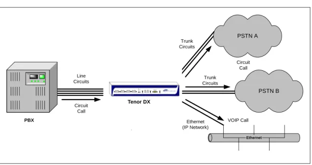
Call Routing/Management Options
Call Routing
Line Circuit Originated Calls.
Calls coming from a Line Circuit may be switched to either the data
network as a VoIP call or to a Trunk Circuit typically for connection to another circuit switched
net-work such as the PSTN. The routing decision made by the Tenor is based upon your configuration
and the dialed number.
Figure 1-3
Line Circuit Call Routing
Trunk Circuit Originated Calls.
A call coming from a Trunk Circuit may be switched to either the
data network as a VoIP call, a Line Circuit, or trunk typically for connection to a termination device
on the user’s premises such as a PBX. The routing decision made by the
Tenor DX
is based upon
your configuration and the dialed number.
Line Circuits Ethernet PSTN B Trunk Circuits Trunk Circuits PSTN A Ethernet (IP Network) Tenor CMS PBX VOIP Call Circuit Call Circuit Call R POWER ALERT RE SET 12 34 56 78 Line/Act 100 Line/Act 100 LAN 1 LAN 2 CONSOLE D IA G
Figure 1-4
Trunk Circuit Call Routing
Intra-trunk Routing - “Hairpinning”.
As a result of intra-trunk routing, incoming calls from a
particular Trunk Circuit are switched by
Tenor DX
to be routed back out the same trunk circuit
rout-ing group.
Figure 1-5
Intra-Trunk Routing
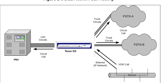
Data Network Calls.
Calls coming from the data network can be routed to the Line Circuit or Trunk
Circuit spans. The Tenor will route calls based upon the dialed number. If the number is configured
Line Circuits Ethernet PSTN B Trunk Circuits Trunk Circuits PSTN A Ethernet (IP Network) Tenor CMS PBX VOIP Call Circuit Call Circuit Call R POWER ALERT RES ET 12 34 56 78 Line/Act 100 Line/Act 100 LAN 1 LAN 2 CONSOLE
DI AG Tenor DX Line Circuits Ethernet PSTN B Trunk Circuits Trunk Circuits PSTN A Ethernet (IP Network) Tenor CMS PBX VOIP Call Circuit Call Circuit Call R POWER ALERT R ES ET 12 34 56 78 Line/Act 100 Line/Act 100 LAN 1 LAN 2 CONSOLE
DI
AG
Figure 1-6
Data Network Call Routing
Routing Table Options
There are four types of routing databases you can configure: Bypass Directory Numbers (BPN),
Hunt Local Directory Numbers (Hunt LDN), Hop-Off Directory Numbers (HDN) and Static Routes.
Bypass Directory Numbers.
Bypass Directory Numbers (BDN) are telephone numbers that are
automatically routed directly from a line circuit to a trunk circuit (PSTN); they will not be routed
VoIP. Some examples of bypass numbers include toll-free calls, emergency calls (i.e., 911), or high
security calls.
Hunt Local Directory Numbers.
A Hunt Local Directory Number (Hunt LDN) is a
phone number
reachable through local Line Circuits.
Hop-Off Directory Number.
A Hop-off PBX call travels over IP, and then “hops” off into the
pub-lic network (PSTN) on the distant side to reduce or eliminate pubpub-lic toll charges (also known as
Leaky Area Map). A Hop-Off Directory Number is routed over the IP to another Tenor location and
then out to the Trunk circuit, possibly to the PSTN as a local call.
Static Routes
. Static Routes are used between networks and other H.323 devices that are not
regis-tered to the network through the Border Element (such as non-Quintum gateways). A static route
associates endpoints (as represented by their IP address) with Directory Number patterns.
Line Circuits Ethernet PSTN B Trunk Circuits Trunk Circuits PSTN A Ethernet (IP Network) Tenor CMS PBX VOIP Call Circuit Call Circuit Call R POWER ALERT RE SE T 12 34 56 78 Line/Act 100 Line/Act 100 LAN 1 LAN 2 CONSOLE DIA G
Call Management Features
Dynamic Call Routing.
Tenor DX
’s intelligent call routing capabilities are state-of-the-art. The unit
automatically detects and supports three call types: voice, fax, and modem.
Tenor DX
will first identify the call origination site—trunk circuit, line circuit, or IP routing group
—and then route the call according to any parameters you have configured in the routing database.
Each call may be routed via circuit switched path between any two circuit groups, or compressed
and transported via VoIP when connecting to an IP routing group. Trunk circuits are those that
typi-cally connect to another circuit switched network such as the PSTN. Line circuits typitypi-cally connect
to a termination device on the user premises, such as a PBX.
Trunk Group Support.
The
Tenor DX
supports trunk groups, which are groups of T1 or E1
chan-nels used to connect the Tenor to other carriers (such as local telephone company) or to PBX
equip-ment used for circuit aggregation.
Public/Private Dial Plan Support.
The
Tenor DX
supports public and private dial plans. A public
dial plan includes numbers which conform to the international dialing plan (E.164) of a country
code + city/area code + local number. For a public dial plan, you can define the numbering plan
structure for the
Tenor DX
to use for outgoing calls.
A private dial plan does not conform to a public dialing plan (i.e., 3 digit dialing plan); through the
Tenor DX
you are able to configure the unique pattern/dialing plan structure, including number
length.
You are able to configure which dial plan to use for incoming and outgoing calls, including whether
other options such as hop-off calls, will use a public or private dial plan.
User Programmable Dial Plan Support.
The User Programmable Dial Plan Support (UPDP)
enables the Tenor to identify a completely customizable set of digit sequences, such as Local,
National, International or Private Numbers.
PassThrough support for certain call types.
Certain call types can be directly routed to a trunk
circuit, without going IP. There are several routing tables you can configure via the
Configuration
Manager
to adjust how the
Tenor DX
unit routes these types of “pass through” numbers. For
exam-ple, you may want to configure 911 as a “bypass number”, which means that all 911 calls coming
into
Tenor DX
from the line circuit will be routed directly to a Trunk circuit presumably connected
to a PSTN. Bypass calls are never routed over IP.
Hop-off PBX Calls.
Hop-off numbers are phone number patterns for calls to be routed out through
trunks. They are entered in a Hop-off Number Directory and associated with trunks where matching
calls should be sent.
H.323 Gatekeeper Services
The
Tenor DX
unit’s built-in H.323 gatekeeper performs IP call routing functions, such as call
con-trol and administrative services to another
Tenor DX
unit, or another H.323 endpoint. The
gate-keeper’s functionality complies with the H.323 industry specifications for voice control and
management.
Gatekeeper
A Gatekeeper in an H.323 network provides call control services and other services to H.323
end-points (i.e., gateways, terminals, and MCUs). The
Tenor DX
has a built-in H.323 gatekeeper which
complies to the H.323 industry specifications for voice control and management. The gatekeeper
performs call routing functions for calls entering and exiting a site.
The Gatekeeper performs IP call routing functions, such as Call Control Signaling and Call
Authori-zation for Gateways, IP phones, and H.323 terminals. The Gatekeeper communicates with other
Gatekeepers through a Border Element. When using a group of
Tenor DX
units, you can assign one
unit as the Gatekeeper for the network. We recommend you configure each as its own gatekeeper.
Tenor DX
supports gatekeeper to gatekeeper communication using the standard LRQ (Location
Request)/LCF (Location Confirm) messaging scheme.
Zone Management
A zone is a group of H.323 defined endpoints controlled by a Gatekeeper. Endpoints can be
gate-ways (i.e.,
Tenor DX
), terminals, and/or multipoint conferencing units (MCUs). Endpoints establish
control channels with a gatekeeper for registration, admission, and security. Call routing information
about the endpoint is sent to the gatekeeper, including: IP address, unit type (gateway, terminal, or
MCU) and routing information (such as phone numbers, number patterns, etc.).
A collection of zones is an administrative domain. An administrative domain provides call routing
services for its zones through gatekeeper to gatekeeper messages or gatekeeper to border element
messages (see below for more information).
Call Registration
When registration from an H.323 endpoint is complete and a call is originated, the call request is
sent to the gatekeeper. The call request provides the Gatekeeper with the dialed number and requests
the routing information. The gatekeeper confirms the dialed number and supplies the endpoint with
the destination IP address. For example, a
Tenor DX
’s gatekeeper will act as the gatekeeper for that
zone and all of the other endpoints will register with it.
Border Element
The
Tenor DX
’s gatekeeper uses a border element to gain access to the routing database of the
administrative domain for the purpose of call completion or any other services that involve
commu-nications with other endpoints out of the administrative domain. The border element functionality is
The primary function of the border element is to collect, manage, and distribute call routing
infor-mation. A gatekeeper will establish a service relationship with a border element; the gatekeeper
pro-vides its zones capabilities and the border element shares call routing capabilities of other zones in
the administrative domain. Through the border element, gatekeepers from multiple zones will be
able to communicate.
A border element also establishes relationships with other border elements to route between
admin-istrative domains. If a gatekeeper cannot resolve an address, it contacts the border element.
In addition, if you are using more than one Tenor unit, you can configure one of the border elements
for that zone. The
Tenor DX
unit can use two border elements: primary and secondary. These work
together as one entity to provide redundancy and fault tolerance; there are no hierarchal differences.
Call Services
Gatekeepers provide services such as addressing, authorization and authentication of terminals and
gateways, bandwidth management, accounting, billing, and charging. Gatekeepers also provide
call-routing services. Specifically, the
Tenor DX
Gatekeeper provides the functions which follow:
Address Translation.
The gatekeeper translates telephone numbers into IP addresses and vice
versa. It performs Alias Address (phone number) to Transport Address (IP address) translation when
an endpoint requests service. The Gatekeeper uses a translation table to translate an Alias Address
(an address such as an H.323 identifier that a user may not understand) to a transport address. The
translation table is updated using Registration messages.
Autodiscovery.
The gatekeeper is discovered in one of the following ways: An endpoint sends an IP
broadcast called a Gatekeeper Request message (GRQ) message (which includes that correct
gate-keeper name) to discover a Gategate-keeper OR the endpoint will discover a gategate-keeper by its IP address.
Border Element Gatekeeper Zone Gatekeeper Zone Gatekeeper Zone Administrative Domain Border Element Gatekeeper Zone Gatekeeper Zone Gatekeeper Zone Administrative Domain
Admissions Control.
All H.323 endpoints must register and request permission to enter the
gate-keeper’s zone; the gatekeeper will confirm or deny access to the network.
The gatekeeper authorizes
network access and protects the integrity of the network using Admissions Request (ARQ),
Admis-sions Confirmation (ACF) and AdmisAdmis-sions Reject (ARJ) messages.
SIP User Agent
SIP (Session Initiation Protocol) is a signaling protocol used to establish a session on an IP network
for voice control and management; it is a request-response protocol that closely resembles Hypertext
Transfer Protocol (HTTP), which forms the basis of the World Wide Web. SIP re-uses many of the
constructs and concepts of Internet protocols such as HTTP and Simple Mail Transfer Protocol
(SMTP). The purpose of SIP is only to establish/change/terminate sessions. SIP is not concerned
with the content or details of the session.
SIP is Transport layer-independent, which means it can be used with any transport protocol: UDP,
TCP, ATM, etc. It is text-based, so it requires no encoding/decoding like H.323. And SIP supports
user mobility, using proxies and redirecting requests to your current location.
When configured for SIP the Tenor will act as a SIP User Agent (Endpoint) as defined in IETF
RFC3261. Multiple user agents allow for separate agents to be allocated to each SIP call. It will be
able to gateway calls to and from the IP network, and Customer Premise Equipment (CPE) such as
phones, PBX's, and FAX machines, or the Public Switched Telephone Network (PSTN). The Tenor
SIP User Agent will work in conjunction with an external SIP proxy or redirect server to route and
connect calls over SIP based networks.
There are three basic components of SIP:
1. User Agent (Endpoint)
•
client element, initiates calls
•
server element, answers calls
2. Network Server (Proxy Server or Redirect Server)
•
name resolution
•
user location
•
redirect and forking
3. Registrar
C
hapter 2: Hardware Components
This chapter tells you what is contained in your hardware package. A description of each component is also included.
Specifically, the following topics are covered:
!
Hardware DescriptionHardware Description
The Tenor DX is a stackable/rack mountable device which provides PSTN and PBX connections (through T1/ E1/PRI lines), as well as connections to the Ethernet LAN and a PC. The unit provides eight RJ-45 ports in which you can connect to a PBX or the PSTN.
The unit’s front panel includes connection jacks, LEDs, a reset button, and a diagnostics option; the back panel includes a power cord connection site, an on/off switch, and a label.
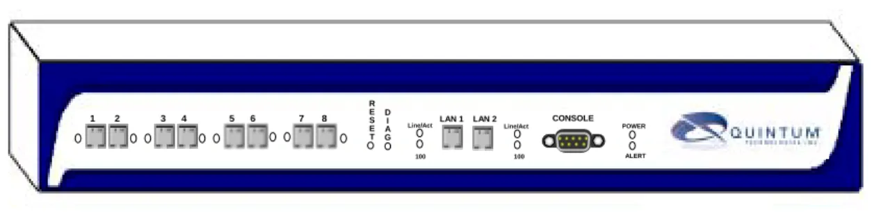
Front Panel Connections and Reset Options
Figure 2-1
Tenor DX
Front Panel
• Ports 1-8. One RJ-45 jack for each port supports a connection to a line side (PBX) or other customer equipment via upstream T1 or E1 lines, or to the trunk side (PSTN) via downstream T1 or E1 lines. Each T1 line provides 24 channels. For each T1 interface, there are two types of signaling supported: Channel Associated Signaling (CAS) and Common Channel Signaling (CCS). For T1 using CAS, chan-nels 1-24 are available; for T1 using CCS, chanchan-nels 1-23 are available.
Each E1 line provides 30B (Bearer) channels and 1D (Data) signaling channel. For each E1 interface, there are two types of signaling supported: Channel Associated Signaling (CAS) and Common Channel Signaling (CCS).
Adjacent port pairs (i.e., 1/2, 3/4, etc.) are configured by default to connect to each other (power off bypass) when the unit is turned off, or when the unit is in Offline mode. This is the preferred method when connecting one of the lines to a PBX, and its adjacent pair to the PSTN. However, if you have adja-cent port pairs that are connected to smaller devices (i.e., both going to PSTN) in which you do not want the two ports to be connected to each other in case of power off or offline, you should set the power off bypass = 0. Each pair of ports (1/2, 3/4, 5/6 and 7/8) have their own online/offline and power off bypass control. See the TenorConfiguration Manager online help or the Command Line Interface (CLI) guide for specific configuration information.
• Reset. Enables you to reset the system.
• Diag. Enables you to perform software diagnostic procedures.
• LAN 1/LAN2. 10/100 Base-T Ethernet ports. LAN 1 port provides an RJ-45 jack for an individual con-nection to a 10/100 Ethernet LAN switch or hub via RJ-45 cable; it is individually configured with a unique IP and MAC address. LAN2 Ethernet port is reserved for future use.
1 2 3 4 5 6 7 8 R E S E T D I A G CONSOLE POWER ALERT LAN 1 LAN 2 Line/Act 100 Line/Act 100 Port Reset
Diag Console Port LAN1/LAN2
Figure 2-2
10/100 BASE-T Ethernet Port Pin Order
Table 2-1
Input/Output 10/100 Ethernet port
• Console port. This RS-232 connector is used for connection to a PC’s serial port via DB-9 serial cable at 38400 BPS 8N1, without flow control. The input/output signals are listed in Table 2-2.
Figure 2-3
DB-9 Female Connector Pin Order
Table 2-2
Serial RS232 DB-9 Connector Pinouts
Pin # Signal Definition Color
1 TX + Transmit Data White w/orange
2 TX - Transmit Data Orange
3 RX + Receive Data White w/green
4 RSVD Reserved Blue
5 RSVD Reserved White w/blue
6 RX - Receive Data Green
7 RSVD Reserved White w/Brown
8 RSVD Reserved Brown
Pin #
Function
Description
1 DTR Data Terminal Ready
2 TXD Transmit Data 3 RXD Receive Data 4 CD Carrier Detect 5 GND Signal Ground 6 N.C. No Connect
5 4 3 2 1
9 8 7 6
7 N.C. No Connect
8 N.C. No Connect
9 N.C. No Connect
Front Panel LEDs
The LEDs display the health of the system. There are different types of LEDs: network, LAN, Alert and Power. For LED definitions, see Table 2-3.
Figure 2-4
Front Panel LEDs
Table 2-3
Front Panel LEDs Definitions
LED
Label LED
Color
Description
Network (PSTN) or PBX
1-8
Red Receive Path Error Indication. Line is not connected or other receive errors.
Yellow Receive Path Error Indication. Line is not connected or other receive errors.
Green Indicates B channels are busy. Off The port is empty.
LAN1
LAN2 (LAN 2 is reserved for future use)
Link/ACT Green On: Link is good.
Flashing: Line is working properly and activity is on the line. Off: Link has failed.
100 Green On: Activity is being transmitted at 100 Mbps.
Off: Activity is being transmitted at 10 Mbps.
Power Power Green On: Indicates power is on.
Off: Power is off.
Alert Alert Amber Operational Status.
Off: Tenor DX is working prop-erly.
On: One or more diagnostic tests have failed. 1 2 3 4 5 6 7 8 R E S E T D I A G CONSOLE POWER ALERT LAN 1 LAN 2 Line/Act 100 Line/Act 100
Back Panel
• AC Receptacle. Receptacle in which to plug in a power cord; the other end will plug into an AC outlet for power.
• Power Switch. Switch to turn power on and off.
• Ground Screw. An earth ground screw provided to connect to earth ground using a Ground Safety Cable (if your AC power plug only has two prongs and does not have a third, grounded prong).
• Label. A label that displays UL, model, and power information. AC Receptacle
Power Switch Ground Screw
Cables
The cables listed in Table 2-4 are required to connect a Tenor DX to various interfaces. Contact Quintum for ordering information, if necessary.
NOTE: A crossover cable is required when connecting to a Line side (PBX) interface (when supplied by Quintum, this is a red RJ-45 cable). A straight cable is required when connecting to the trunk side (PSTN) interface (when supplied by Quintum, this is a green RJ-45 cable).
Table 2-4
Cables Supported
RJ-45 Cables
RJ-45 cable connector pinouts are given in this section to help you identify the proper connector to accommo-date your specific networking requirements. The RJ-45 (ISO 8877) connector is the EIA/TIA standard for Unshielded Twisted Pair (UTP) cable; the wiring color codes are UTP Standard Coloring. The pin order is shown in Figure 2-5.
Figure 2-5
RJ-45 Pin Order
Cable Usage
RJ-45 to RJ-45 Crossover Cable (this cable is red if provided by Quintum)
T1/E1 connection Line Side Side (PBX) inter-face.
RJ-45 to RJ-45 Straight Through cable (this cable is green if provided by Quintum)
T1/E1 connection to Trunk Side (PSTN) inter-face.
RJ-45 Ethernet cable (grey or white) Connection to Ethernet LAN 10/100. DB-9 Serial RS-232 Connection to PC’s asynchronous console
port.
Detachable (IEC) AC Power Supply Cord Connection to AC power jack.
8 1 1 8 Side View Top View
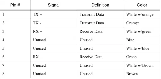
RJ-45 Ethernet Cable (10/100)
An RJ-45 (10/100BaseT) straight through shielded cable is used to connect Tenor DX to an Ethernet LAN. Cable pinouts are listed in Table 2-5. Color specifications are applicable to the RJ-45 cable provided.
Figure 2-6
RJ-45 (10/100BT) Connector Pinouts
Table 2-5
RJ-45 (10/100BT) Connector Pinouts
Pin # Signal Definition Color
1 TX + Transmit Data White w/orange
2 TX - Transmit Data Orange
3 RX + Receive Data White w/green
4 Unused Unused Blue
5 Unused Unused White w/blue
6 RX - Receive Data Green
7 Unused Unused White w/Brown
8 Unused Unused Brown
Pin # Connects to Pin #
1 2 3 4 5 6 7 8 1 2 3 4 5 6 7 8
RJ-45 to RJ-45 Straight Cable (T1/E1/PRI WAN to Trunk Side)
An RJ-45 (T1/E1) straight cable is used to connect Tenor DX T1/E1 (1-8) port to the Trunk Side (PSTN). Cable pinouts are provided below. If this cable is provided by Quintum, the color is green. The color specifica-tions are applicable to the RJ-45 straight cable provided.
Figure 2-7
RJ-45 (T1/E1/PRI) Connector Pinouts
Table 2-6
RJ-45 Connector Pinouts for T1/E1/PRI
Pin # Signal Definition Color
1 RX ring Receive Ring White w/orange
2 RX tip Receive Tip Orange
3 RSVD Reserved White w/green
4 TX ring Transmit Ring Blue
5 TX tip Transmit Tip White w/blue
6 N.C No Connect Green
7 N.C. No Connect White w/Brown
8 N.C. No Connect Brown
Pin # Connects to Pin #
1 2 3 4 5 6 7 8 1 2 3 4 5 6 7 8
RJ-45 to RJ-45 Crossover Cable (T1/E1/PRI WAN to PBX)
An RJ-45 (T1/E1) crossover cable is used to connect Tenor DX T1/E1 (1-8) port to the Line Side (PBX). Cable pinouts are provided below. If this cable is provided by Quintum, the color is red. The color specifica-tions are applicable to the RJ-45 crossover cable provided.
Figure 2-8
RJ-45 Crossover Cable Pinouts
Table 2-7
RJ-45 Connector Pinouts for T1/E1/PRI (1-8) port
Pin # Signal Definition Color for Connector 1 Color for Connector 2
1 RX ring Receive Ring White w/orange Blue
2 RX tip Receive Tip Orange White w/blue
3 RSVD Reserved
-4 TX ring Transmit Ring Blue White w/orange 5 TX tip Transmit Tip White w/blue Orange
6 N.C No Connect -
-7 N.C. No Connect -
-8 N.C. No Connect -
-Pin # Connects to Pin #
1 2 3 4 5 6 7 8 1 2 3 4 5 6 7 8 Connector 1 Connector 2
DB-9 Serial RS-232 Cable
The Serial RS-232 9-pin cable with a DB-9 male connector (with RS-232 interface) is used to connect the Tenor DX to your PC’s asynchronous serial port. The pin order for DB-9 male and female connectors are shown in Figure 2-9 and Figure 2-10.
Figure 2-9
DB-9 Male Connector Pin Order
Figure 2-10
DB-9 Female Connector Pin Order
Figure 2-11
DB-9 Connector Pinouts
Table 2-8
DB-9 Connector Pinouts
Pin #
Function
Description
Pin #
1 DTR Data Terminal Ready 1
2 TXD TransmitData 2 3 RXD Receive Data 3 4 CD Carrier Detect 4 5 GND Signal Ground 5 6 N.C. No Connect 6 7 N.C. No Connect 7 8 N.C. No Connect 8 9 N.C. No Connect 9
1 2 3 4 5
6 7 8 9
5 4 3 2 1
9 8 7 6
P in # Con nects to P in # 1 2 3 4 5 6 7 8 9 1 2 3 4 5 6 7 8 9C
hapter 3: Installation
This chapter gives you installation instructions, as well as how to position the Tenor DX successfully within your network.
Specifically, the following topics are covered:
!
Installation!
Connection!
Install Ground Safety Cable!
Power up the SystemInstallation
Before you begin the actual installation, review the pre-installation guidelines which follow and inspect the package contents.
Pre-Installation Guidelines
• Always use an anti-static wrist strap when handling the unit.
• Do not open the unit cover. Inside parts have hazardous voltages and are extremely sensitive to static. If the unit has been opened, your warranty is void.
• Do not connect equipment in wet conditions and keep away from dusty areas.
• The area must not exceed the temperature and humidity guidelines outlined in Appendix A: Technical Specifications.
• Avoid exposing the chassis to excessive vibrations.
• Mechanical loading of rack should be considered so that the rack remains stable and unlikely to tip over. Ensure no equipment is put on top of the chassis.
Inspect Package Contents
Before you install the hardware, ensure the following components are included in your shipment: • Tenor Tenor DX and Mounting Hardware
• 1 AC Power Cable • DB-9 RS-232 Serial Cable • RJ-45 LAN Cable
• Correct quantity of RJ-45 cables associated with your custom configuration • Product Guide in CD format
Rack Install
Locate the Tenor DX unit within the same area as your PBX, Ethernet hub, switch, router, and/or PSTN patch panel. The chassis is intended to be installed in a 19” rack.
Mounting brackets are attached to the chassis; the rack is not included with your system. Included with the chassis are the screws and clip nuts listed below. The sizes should allow installation in most racks. If your rack does not use the same size screws listed in the table, please consult the instructions you received with the rack.
Required Materials
• 19” rack (not included with system)
• #8 - 32 x 3/8 screws (qty: 2) (included with system) • screws as required by your rack manufacturer Install the chassis in a rack as follows:
1. Choose a position for the chassis within the rack.
WARNING:
If the Tenor DX unit is the only equipment installed in the rack, ensure it is level with the rack to avoid the rack from becoming unbalanced. Mount as low as possible to avoid a high center of gravity.2. Align the unit’s mounting brackets flush with the rack’s mounting holes (see Figure 3-1) and follow the vendor specific instructions for rack installation. The screws provided require a Phillips #2 screwdriver. 3. Ensure the chassis is secured firmly to the rack.
Figure 3-1
Rack Installation (Front View)
Wall Mount
There are two mounting brackets available to mount the unit to the wall.
Pre-installation Guidelines
• Ensure the wall is level and stable. • Do not attach the unit to a temporary wall.
• Ensure the wall mounting area is within cord distance of the power outlet.
Required Materials
• 2 wall mounting brackets (including 2 screws) • Drill
• 3/16 drill bit
• Measuring tape or ruler • Hammer
• Phillips head screwdriver
Rack Mounting Holes
Attach the unit to the wall as follows:
1. Determine the wall area to mount the unit. With chalk or a soft pencil, mark the install area according to Figure 3-2.
NOTE: Ensure the unit is level.
Figure 3-2
Wall Mounting Dimensions
2. Position and attach one mounting bracket to the unit using a screw existing in the system and one screw included with the package. See Figure 3-3.
3. Position and attach the other mounting bracket using a screw existing in the system and the remaining screw in the package. See Figure 3-3.
Figure 3-3
Wall Mount Installation
4. Mount the unit to the wall using the four remaining screws included with the system. 5. Ensure the unit is firmly mounted against the wall.
7 3/4” (19.9cm)
3/16”
Mounting Brackets
Note: Ensure unit is level.
Attach each bracket to the
unit using 1 screw already installed and 1 screw already included in the unit (unscrew and re-insert) with the package.
Connection
Connect to Line Interface - PBX
Since there are many different PBX devices and connection methods, your individual PBX will determine the connection method you use to connect to the unit. For example, your PBX may be connected using a patch panel, punch down block, wire wrapped blocks, etc. If you are not sure about installation procedures, contact the network administrator or review the documentation you received with the PBX.
Adjacent port pairs (i.e., 1/2, 3/4, etc.) are configured by default to connect to each other (power off bypass) when the unit is turned off, or when the unit is in Offline mode. This is the preferred method when connecting one of the lines to a PBX, and its adjacent pair to the PSTN. However, if you have adjacent port pairs that are connected to smaller devices (i.e., both going to PSTN) in which you do not want the two ports to be con-nected to each other in case of power off or offline, you should set the power off bypass = 0. Each pair of ports (1/2, 3/4, 5/6 and 7/8) have their own online/offline and power off bypass control. See the TenorConfiguration Manager online help or the Command Line Interface (CLI) guide for specific configuration information. You may use your PBX documentation, along with other PBX materials, to determine how to connect the other end of the RJ-45 cable to your PBX. See Chapter 2: Hardware Components for the RJ-45 cable pinouts you can use to acquire another cable or adapter that may be required to connect your specific PBX to the unit. No changes are required to the PBX itself; you will need only the correct cable or adapter.
The instructions which follow tell you how to connect an RJ-45 cable (included in your package) between one of the eight network ports on the Tenor DX and a PBX. See Chapter 2: Hardware Components for a list of RJ-45 cable pinouts you can use to make a custom cable.
Figure 3-4
Connect to Line Interface
Connect to Line Interface as follows:
1. Plug one end of the crossover RJ-45 cable into one of the eight network ports on the front of the unit. (This cable from Quintum would be the red RJ-45 crossover cable.) See Chapter 2: Hardware Components for cable pinouts if you are making your own cable.
2. Connect the other end of the crossover RJ-45 cable into the appropriate port on the PBX. (If another cable or adapter is required, see Chapter 2: Hardware Components for RJ-45 crossover pinout information.)
NOTE: If you are connecting to an external CSU, ensure the Digital Interface is configured as short haul (or DSX-1); otherwise, configure the Digital Interface to DS-1 to enable the built in CSU via Com-mand Line Interface (CLI). See Chapter 4: Getting Started: Tenor Configuration Manager/Tenor Monitor. 1 2 3 4 5 6 7 8 R E S E T D I A G CONSOLE POWER ALERT LAN 1 LAN 2 Line/Act 100 Line/Act 100 PBX RJ-45 Crossover Insert ports 1-8
Connect to Trunk Interface - PSTN
Adjacent port pairs (i.e., 1/2, 3/4, etc.) are configured by default to connect to each other (power off bypass) when the unit is turned off, or when the unit is in Offline mode. This is the preferred method when connecting one of the lines to a PBX, and its adjacent pair to the PSTN. However, if you have adjacent port pairs that are connected to smaller devices (i.e., both going to PSTN) in which you do not want the two ports to be con-nected to each other in case of power off or offline, you should set the power off bypass = 0. Each pair of ports (1/2, 3/4, 5/6 and 7/8) have their own online/offline and power off bypass control. See the TenorConfiguration Manager online help or the Command Line Interface (CLI) guide for specific configuration information.
Figure 3-5
Connect to Trunk Interface
1. Plug one end of the straight through RJ-45 cable into one of the eight network ports on the front of the unit. The cable from Quintum would be the green RJ-45 cable. See Chapter 2: Hardware Components for cable pinouts if you are making your own cables, or if you wish to attach the table to a punch down block. 2. Connect the other end of the RJ-45 straight cable to the patch panel which houses your telephone lines.
NOTE: If you are connecting to an external CSU, ensure the Digital Interface is configured as short haul (or DSX-1), otherwise, configure the Digital Interface to DS-1 to enable the built-in CSU via Com-mand Line Interface (CLI). See Chapter 4: Getting Started: Tenor Configuration Manager/Tenor Monitor.
NOTE: Connecting to the patch panel may require trained telephone personnel.
1 2 3 4 5 6 7 8 R E S E T D I A G CONSOLE POWER ALERT LAN 1 LAN 2 Line/Act 100 Line/Act 100 PSTN Patch Panel RJ-45
Connect to Ethernet LAN
You can use these instructions for general connection purposes only. The Ethernet hub/switch manufacturer’s documentation should provide specific instructions for connection to another device, such as the Tenor DX. Only LAN 1 is available for use; LAN 2 is reserved for future use.
Figure 3-6
Connect to Ethernet Hub/Switch
1. Plug one end of the grey or white RJ-45 Ethernet cable into the port labeled LAN 1.
2. Plug the other end of the cable into one of the Ethernet hub/switch ports. If a custom cable or adapter is required, see Chapter 2: Hardware Components for Ethernet RJ-45 10/100.
1 2 3 4 5 6 7 8 R E S E T D I A G CONSOLE POWER ALERT LAN 1 LAN 2 Line/Act 100 Line/Act 100 Data Network Ethernet Hub/Switch
Connect to PC Console
You will need to connect the Tenor DX to your workstation’s serial port via RS-232 connection. (This connec-tion will be used when you assign an IP address to the unit.) For the instrucconnec-tions below, it is assumed you are connecting to a Windows PC.
Figure 3-7
Connect to PC Com Port
1. Insert the male end of the DB-9 cable into the port labeled Console. (See Chapter 2: Hardware Compo-nents for RS-232 connector pinouts.)
2. Insert the female end of the DB-9 cable into your workstation’s serial port (see your PC documentation for more information about this port).
1 2 3 4 5 6 7 8 R E S E T D I A G CONSOLE POWER ALERT LAN 1 LAN 2 Line/Act 100 Line/Act 100 DB-9
Install Ground Safety Cable (if required)
The Tenor DX provides an Earth Ground screw (a #6 screw). This screw provides earth ground to the unit if the AC power receptacle you are plugging into does not contain a ground prong (the Quintum supplied power cable has a three prong connector). To provide ground via the grounding screw, you will need to connect the grounding screw to a Ground Safety Cable, which can then be connected to an approved safety earth ground. Connect the Ground Safety Cable as follows:
1. Unscrew the existing screw from the grounding hole.
2. Place the screw through the ring connector at one end of the ground safety cable. 3. Attach the screw securely to the threaded grounding hole.
4. Connect the other end of the ground safety cable to an approved electrically grounded object. Consult with a licensed electrician if you are unclear about this operation.
Power up the System
Once you have all cables connected properly, you are ready to turn the system on as follows: 1. Plug in the power cord to an AC outlet.
2. Locate the on/off switch on the back of the unit and click the switch to On.
The unit will power up and the LEDs will flash and turn off; the power LED will remain lit. For information about the LEDs, see Chapter 2: Hardware Components.
Once the unit is powered up, you are ready to assign an IP address. See the following section Assign IP Address.
Assign IP Address
Before you can configure a Tenor DX, you need to assign a valid IP address. When a Tenor DX is shipped to a customer, you need to assign a valid IP address for each unit. An IP address is a 32 bit (up to 12 numeric char-acters) address used to identify each network device in the TCP/IP network. If the unit does not have an IP address, data will not be able to be sent to or from the unit.
Communication between the Tenor and the PC is enabled via RS-232 connection and terminal emulation soft-ware. The instructions below assume you are running HyperTerminal (running Windows 95 or later) on your PC. For all other terminal emulation packages, the specific Tenor commands used to assign the IP address will be the same, but the software specific instructions will be different. Consult the applicable documentation for more information.
You can re-configure the IP address using the procedure which follows. 1. Press the Tenor DX’s power switch to On.
2. Click on Start> Programs> Accessories> Communications>HyperTerminal> Run. The Connection Description window will be displayed.
3. Enter a connection name(i.e., name for each unit such as Tenor DX New Jersey). 4. Click Ok.
5. Choose the serial port on your PC from the Connect Using drop down list box (i.e., Direct to Com 1). Click
Ok. The Com1 Properties window will be displayed. See Figure 3-9.
Figure 3-9
Port Settings Window6. From the Bits Per Second drop down list box, choose 38400. 7. From the Data Bits drop down list box, choose 8.
8. From the Parity drop down list box, choose None. 9. From the Stop bits drop down list box, choose 1.
11. Click Ok and a connection to the Tenor will be established. Information about the unit will scroll on the screen.
12. Enter login and password. Both are admin by default.
13. A message will appear on the screen “Tenor Analog does not have an Ethernet interface configured. Would you like to configure an Ethernet Interface?” (y/n).
14. Type y.
15. For IP Address, enter the IP address for the Tenor unit.
16. For Subnet Mask, enter the subnet mask. This address is used to differentiate the network portion of the IP address from the host portion of the IP address.
17. For Default Gateway, choose whether there should be a default gateway (router) which routes packet data outside of your LAN and enter its IP address.
18. A message will appear on the screen “Tenor Digital Ethernet Interface successfully configured.” The Tenor will restart using the new Ethernet settings.
Tenor will restart using the new Ethernet settings.
Change IP Address
You are able to change the IP address in which the unit is attached as follows:
NOTE: The instructions below assume you are running Windows 2000 or above. 1. Press the Tenor DX’s power switch to On.
2. Click on Start> Programs> Accessories> Communications>HyperTerminal> Run. The Connection Description window will be displayed.
3. Enter a connection name(i.e., name for each unit such as Tenor DX New Jersey). 4. Click Ok.
5. Choose the serial port on your PC from the Connect Using drop down list box (i.e., Direct to Com 1). Click
Figure 3-10
Port Settings Window6. From the Bits Per Second drop down list box, choose 38400. 7. From the Data Bits drop down list box, choose 8.
8. From the Parity drop down list box, choose None. 9. From the Stop bits drop down list box, choose 1. 10. From the Flow control drop down list box, choose None.
11. Press the Tenor AS power switch to On. After the bootup sequence, the login prompt will appear. 12. Enter a login name. The default login name is admin.
13. Enter a password. The default password is admin. (Once you are up and running, changing the password is a good idea for security purposes). Step through each of the following parameters and enter the correct values for your installation: IP address, Subnet Mask and Default Gate-way.
14. At the Quintum prompt, type ei to reach the Ethernet prompt and then type config to change to the Con-figuration mode.
15. To set the IP address, type set ipa followed by the IP address.
16. To set the Subnet Mask, type set subnetmask, followed by the subnet mask. 17. Type siprd to change to the Static IP Route Directory.
18. To set the Default Gateway IP, type change 1 g followed by the IP address for the default gateway IP. 19. Type submit.
20. Type maint to reach the maintenance mode and then mc. Type reset. A confirmation message will ask if you want to reset the unit. Type yes to reset the unit. The reboot enables the Tenor to incorporate the new settings.
Load Software Upgrade
To upgrade the software, download the upgrade from the CD ROM you received with the unit, or
C
hapter 4: Getting Started:
Tenor
Configu-ration Manager/Tenor Monitor
This chapter tells you how to get started configuring and monitoring the Tenor DX through the Tenor Config-uration Manager and the Tenor Monitor.
!
Overview!
Tenor Configuration ManagerOverview
The Tenor Configuration Manager is a user-friendlywindows-basedstand-alone GUI which enables you to configure a number of Quintum products, including the Tenor DX. The software was designed to run on any PC; you simply designate the IP address for the Tenor product (i.e., Tenor DX) on which you would like to configure or perform monitoring functions.
The TenorConfigurationManager and Tenor Monitor enable you toperformconfiguration and monitoring tasks. For complete information, including all field definitions and extensive usage instructions, see the Tenor Configuration Manager/Tenor Monitor User Guide andthe Command Line InterfaceUser Guide (or the Online Help available with the software).
Tenor Configuration Manager
The Tenor Configuration Manager is used to configure all aspects of the Tenor DX, including system, Ether-net, CDR, signaling, circuit, and VoIP configuration. Through the Configuration Manager, you are able to configure all aspects of the Tenor unit.
The manager is a user-friendly GUI which enables you to configure Quintum products; you designate the IP address of the Tenor product you want to configure. A menu tree—which displays all configuration options in the system—is divided into four main areas: System Wide Configuration, Ethernet Configuration, VoIP Con-figuration, and Circuit Configuration.
• System Wide Configuration. The configuration items under System Wide Configuration include chassis, dial plan, and assorted server information.
• Ethernet Configuration. The Ethernet Configuration menu includes options for configuring Ethernet interface information as well as Static IP, NAT IP and Filter IP information.
• VoIP Configuration. The VoIP Configuration prompt contains the major sub-prompts for configuring the parameters which pertain to its VoIP element status, such as Gateway, Gatekeeper, Border Element, and Signaling Group.
• Circuit Configuration. Through the Circuit Configuration options, you are able to set auto-switch, sig-naling, and trunk group information.
Getting Started with Configuration
This section gives instructions for getting started with the Tenor Configuration Manager. For detailed infor-mation about the installation procedure, see the Tenor Configuration Manager/Tenor Monitor User’s Guide.
NOTE: As an alternate to configuring via Tenor Configuration Manager, you can configure the unit via Command Line Interface (CLI). For information about the CLI, see Chapter 5: Getting Started: Command Line Interface (CLI) or the Command Line Interface User Guide you received with the unit.
NOTE: Ensure the software is installed and running.
1. Access the Tenor Configuration Manager icon (located in the area in which you specified during installa-tion). For example, click on Start > Programs >Quintum Tenor Configuration Manager> Tenor Config Manager. The Tenor Configuration Manager will launch. The Specify Tenor IP Address window will be displayed.
2. From the Tenor IP Address drop down box, click on Specify New IP Address (if the IP address is already listed from a previous login, select that IP address and you will automatically be connected).
3. Enter the IP address of the Tenor unit in which you would like to configure.
4. Enter the Tenor Server Port (the value must match the port numbers set via CLI; the default entry is 8080). 5. Click Ok. The Confirm Login and Password screen will be displayed.
6. Enter a user name and password (the default user name is admin; the default password is admin). Click