TECHNICAL REPORT
TR-098
Internet Gateway Device Data Model for TR-069
Issue: 1 Amendment 2
Issue Date: September 2008
Internet Gateway Device Data Model for TR-069
TR-098 Amendment 2
Notice
The Broadband Forum is a non-profit corporation organized to create guidelines for broadband network
system development and deployment. This Broadband Forum Technical Report has been approved by
members of the Forum. This Broadband Forum Technical Report is not binding on the Broadband Forum,
any of its members, or any developer or service provider. This Broadband Forum Technical Report is
subject to change, but only with approval of members of the Forum.
This Broadband Forum Technical Report is provided "as is," with all faults. Any person holding a
copyright in this Broadband Forum Technical Report, or any portion thereof, disclaims to the fullest extent
permitted by law any representation or warranty, express or implied, including, but not limited to –
(a)
any warranty of merchantability, fitness for a particular purpose, non-infringement, or title;
(b)
any warranty that the contents of this Broadband Forum Technical Report are suitable for any
purpose, even if that purpose is known to the copyright holder;
(c)
any warranty that the implementation of the contents of the documentation will not infringe any
third party patents, copyrights, trademarks or other rights.
This Broadband Forum publication may incorporate intellectual property. The Broadband Forum
encourages but does not require declaration of such intellectual property. For a list of declarations made by
Broadband Forum member companies, please see
http://www.broadband-forum.org
.
Broadband Forum Technical Reports may be copied, downloaded, stored on a server or otherwise
re-distributed in their entirety only. The text of this notice must be included in all copies.
Internet Gateway Device Data Model for TR-069
TR-098 Amendment 2
Issue History
Issue Number
Issue Date
Issue Editor
Changes
Issue 1 September 2005 Jeff Bernstein, 2Wire
Barbara Stark, BellSouth
Issue 1 Issue 1
Amendment 1
November 2006 Jeff Bernstein, 2Wire
John Blackford, 2Wire Mike Digdon, SupportSoft Heather Kirksey, Motive William Lupton, 2Wire Anton Okmianski, Cisco
Clarification of original document
Issue 1 Amendment 2
September 2008 Christele Bouchat, Alcatel William Lupton, 2Wire
Clarification of Amendment 1; Data model extensions (v1.4); See section 1 for further details
Technical comments or questions about this Technical Report should be directed to:
Editors
William Lupton
2Wire
Christele Bouchat
Alcatel-Lucent
DSLHome™
Technical
Working Group
Chairs
Greg Bathrick
PMC-Sierra
Heather Kirksey
Motive
Internet Gateway Device Data Model for TR-069
TR-098 Amendment 2
Table of Contents
1
Introduction ... 10
1.1
Terminology... 11
1.2
Document Conventions ... 12
2
Data Model Definition ... 12
2.1
General Notation ... 12
2.2
Data Types ... 12
2.3
Vendor-Specific Parameters ... 14
2.4
InternetGatewayDevice Data Model ... 15
2.4.1
Inform and Notification Requirements ...158
2.4.2
Version 1.0 Data Model Requirements ...169
3
Profile Definitions ...170
3.1
Notation ...170
3.2
Baseline Profile ...170
3.3
EthernetLAN Profile ...175
3.4
USBLAN Profile ...176
3.5
WiFiLAN Profile ...177
3.6
WiFiWMM Profile ...178
3.7
WiFiWPS Profile ...179
3.8
ADSLWAN Profile ...179
3.9
ADSL2WAN Profile ...181
3.10
VDSL2WAN Profile ...182
3.11
PTMWAN Profile ...184
3.12
EthernetWAN Profile ...185
3.13
POTSWAN Profile ...185
3.14
QoS Profile ...186
3.15
QoSDynamicFlow Profile ...188
3.16
QoSStats Profile ...189
3.17
Bridging Profile ...190
3.18
BridgingPortVLAN Profile ...191
3.19
Time Profile ...191
3.20
CaptivePortal Profile ...192
3.21
IPPing Profile...192
3.22
TraceRoute Profile ...193
3.23
Download Profile ...193
3.24
DownloadTCP Profile ...194
3.25
Upload Profile ...194
3.26
UploadTCP Profile ...195
3.27
UDPEcho Profile ...195
3.28
UDPEchoPlus Profile ...195
3.29
ATMLoopback Profile ...195
3.30
DSLDiagnostics Profile ...196
3.31
ADSL2DSLDiagnostics Profile ...196
3.32
VDSL2DSLDiagnostics Profile ...197
3.33
DeviceAssociation Profile ...198
3.34
UDPConnReq Profile ...198
3.35
DHCPCondServing Profile ...199
3.36
DHCPOption Profile ...199
Normative References ...201
Annex A.
Queuing and Bridging ...203
A.1
Queuing and Bridging Model ...203
A.1.1
Packet Classification ...203
A.1.2
Policing ...206
A.1.3
Queuing and Scheduling ...206
A.1.4
Bridging ...207
A.2
Default Layer 2/3 QoS Mapping ...209
A.3
URN Definitions for App and Flow Tables ...210
A.3.1
ProtocolIdentifier ...210
Internet Gateway Device Data Model for TR-069
TR-098 Amendment 2
A.3.3
FlowTypeParameters ...211
A.4
Example Queuing Architecture for RG (from TR-059) ...211
A.5
Layer2Bridging Use Case: Interface Based Bridging ...213
A.6
Relationship between Layer2Bridging and LANDevice / WAN**Connection ...213
A.6.1
Populating the Data Model on Reboot ...214
A.6.2
Updating the Data Model on Configuration Changes ...215
A.6.3
Bridging Behavior when Layer2Bridging is not Implemented ...215
A.6.4
Case Studies ...215
Annex B.
LinkType and ConnectionType Interdependencies ...218
Appendix I.
Managed bridge configuration in a multi-PVC scenario ...220
I.1
Description of scenario ...220
I.1.1
Network Traffic Classes and Priorities ...220
I.1.2
Mapping to PVCs ...221
I.2
Example Configuration ...222
I.2.1
IGD WAN Connection Device Definitions ...223
I.2.2
IGD Default Queue Definitions ...224
I.2.3
IGD Upstream Classification definitions ...224
I.2.4
IGD Upstream Queue definitions ...225
I.2.5
IGD DHCP Server ...226
I.2.6
IGD DHCP Conditional Serving Pool ...226
Appendix II.
Use of the Bridging Objects for VLAN Tagging ...228
II.1
Tagged LAN to tagged WAN traffic (VLAN bridging) ...230
II.2
Tagged LAN to tagged WAN traffic (special case with VLAN ID translation) ...231
II.3
Untagged LAN to tagged WAN traffic ...233
II.4
Internally generated to tagged WAN traffic ...236
II.5
Other issues ...237
II.5.1
More than one LAN interface in a bridge ...237
II.5.2
802.1D (re-)marking ...237
Internet Gateway Device Data Model for TR-069
TR-098 Amendment 2
List of Figures
Figure 1 – Positioning in the End-to-End Architecture ... 10
Figure 2 – Queuing model of an Internet Gateway Device ...203
Figure 3 – Queuing and Scheduling Example for RG ...212
Figure 4 – Example of interface-based bridging ...213
Figure 5 – WAN / LAN bridged example ...216
Figure 6 – WAN / LAN routed example ...216
Figure 7 – Triple Play Service ...220
Figure 8 – Triple Play Upstream Priorities ...221
Figure 9 – IGD Physical Ingress/Egress Interfaces Block Diagram ...222
Figure 10 – IGD Upstream Data Model Diagram ...223
Figure 11 – Examples of VLAN configuration based on Layer2Bridging ...229
Internet Gateway Device Data Model for TR-069
TR-098 Amendment 2
List of Tables
Table 1 – Data types ... 12
Table 2 – Definition of InternetGatewayDevice:1 ... 15
Table 3 – Forced Inform parameters for an Internet Gateway Device ...159
Table 4 – Forced Active Notification parameters for an Internet Gateway Device ...159
Table 5 - Default Active Notification parameters for an Internet Gateway Device ...160
Table 6 – Parameters for which Active Notification MAY be denied by the CPE ...160
Table 7 – Baseline profile definition for InternetGatewayDevice:1 ...170
Table 8 – EthernetLAN profile definition for InternetGatewayDevice:1 ...175
Table 9 – USBLAN profile definition for InternetGatewayDevice:1 ...176
Table 10 – WiFiLAN profile definition for InternetGatewayDevice:1 ...177
Table 11 – WiFiWMM:1 profile definition for InternetGatewayDevice:1 ...178
Table 12 – WiFiWPS:1 profile definition for InternetGatewayDevice:1 ...179
Table 13 – ADSLWAN:1 profile definition for InternetGatewayDevice:1 ...179
Table 14 – ADSL2WAN:1 profile definition for InternetGatewayDevice:1 ...181
Table 15 – VDSL2WAN:1 profile definition for InternetGatewayDevice:1 ...182
Table 16 – PTMWAN:1 profile definition for InternetGatewayDevice:1 ...184
Table 17 – EthernetWAN:1 profile definition for InternetGatewayDevice:1 ...185
Table 18 – POTSWAN:1 profile definition for InternetGatewayDevice:1 ...185
Table 19 – QoS profile definition for InternetGatewayDevice:1 ...186
Table 20 – QoSDynamicFlow profile definition for InternetGatewayDevice:1 ...188
Table 21 – QoSStats:1 profile definition for InternetGatewayDevice:1 ...189
Table 22 – Bridging profile definition for InternetGatewayDevice:1 ...190
Table 23 – BridgingPortVLAN:1 profile definition for InternetGatewayDevice:1 ...191
Table 24 – Time profile definition for InternetGatewayDevice:1 ...191
Table 25 – CaptivePortal:1 profile definition for InternetGatewayDevice:1 ...192
Table 26 – IPPing:1 profile definition for InternetGatewayDevice:1 ...192
Table 27 – TraceRoute:1 profile definition for InternetGatewayDevice:1 ...193
Table 28 – Download:1 profile definition for InternetGatewayDevice:1 ...193
Table 29 – DownloadTCP:1 profile definition for InternetGatewayDevice:1 ...194
Table 30 – Upload:1 profile definition for InternetGatewayDevice:1 ...194
Table 31 – UploadTCP:1 profile definition for InternetGatewayDevice:1 ...195
Table 32 – UDPEcho:1 profile definition for InternetGatewayDevice:1 ...195
Table 33 – UDPEchoPlus:1 profile definition for InternetGatewayDevice:1 ...195
Table 34 – ATMLoopback:1 profile definition for InternetGatewayDevice:1 ...195
Table 35 – DSLDiagnostics:1 profile definition for InternetGatewayDevice:1 ...196
Table 36– ADSL2DSLDiagnostics:1 profile definition for InternetGatewayDevice:1 ...196
Table 37 – VDSL2DSLDiagnostics:1 profile definition for InternetGatewayDevice:1 ...197
Table 38 – DeviceAssociation Profile definition for InternetGatewayDevice:1 ...198
Table 39 – UDPConnReq:1 Profile definition for InternetGatewayDevice:1 ...198
Table 40 – DHCPCondServing:1 profile definition for InternetGatewayDevice:1 ...199
Table 41 – DHCPOption:1 profile definition for InternetGatewayDevice:1 ...199
Table 42 – Default Layer 2/3 QoS Mapping ...209
Table 43 – ProtocolIdentifer URNs ...210
Table 44 – FlowTypeParameter values for FlowType urn:dslforum-org:pppoe ...211
Table 45 – LinkType and ConnectionType Interdependencies for a WANPPPConnection ...218
Table 46 – LinkType and ConnectionType Interdependencies for a WANIPConnection...219
Table 47 – Tagged LAN to tagged WAN configuration ...230
Table 48 – Tagged LAN to tagged WAN configuration (VLAN ID translation; LAN-to-WAN) ...232
Table 49 – Tagged LAN to tagged WAN configuration (VLAN ID translation; WAN-to-LAN) ...233
Table 50 – Untagged LAN to tagged WAN configuration ...234
Internet Gateway Device Data Model for TR-069
TR-098 Amendment 2
Internet Gateway Device Data Model for TR-069
TR-098 Amendment 2
Summary
Internet Gateway Device Data Model for TR-069
TR-098 Amendment 2
1 Introduction
This document describes the Internet Gateway Device data model for the CPE WAN Management Protocol
(CWMP). TR-069 defines the generic requirements of the management protocol methods which can be
applied to any TR-069 CPE. It is intended to support a variety of different functionalities to manage a
collection of CPE, including the following primary capabilities:
•
Auto-configuration and dynamic service provisioning
•
Software/firmware image management
•
Status and performance monitoring
•
Diagnostics
The ability to manage the home network remotely has a number of benefits including reducing the costs
associated with activation and support of broadband services, improving time-to-market for new products
and services, and improving the user experience.
If TR-069 defines the generic methods for any device, other documents (such as this one) specify the
managed objects, or data models, which are collections of objects and parameters on which the generic
methods act to configure, diagnose, and monitor the state of specific devices and services.
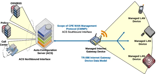
The following figure places TR-069 and this document in the end-to-end management architecture:
OSS/BSS Call Center Policy Auto-Configuration Server (ACS) Managed Internet Gateway Device TR:098 Internet Gateway Device Data Model
Managed LAN Device Managed LAN Device Managed LAN Device
Scope of CPE WAN Management Protocol (CWMP):
ACS Southbound Interface
ACS Northbound Interface OSS/BSS Call Center Policy Auto-Configuration Server (ACS) Managed Internet Gateway Device TR:098 Internet Gateway Device Data Model
Managed LAN Device Managed LAN Device Managed LAN Device
Scope of CPE WAN Management Protocol (CWMP):
ACS Southbound Interface
ACS Northbound Interface
Figure 1 – Positioning in the End-to-End Architecture
The ACS is a server that resides in the network and manages devices in the subscriber premises. It uses the
methods, or RPCs, defined to TR-069 to get and set the state of the device, initiate diagnostic tests,
download and upload files, and manage events. This document defines those objects applicable to
management of an Internet Gateway Device delivering broadband service.
The Internet Gateway Device data model follows the conventions defined in [3] for versioning of data
models and the use of profiles.
This document, TR-098 Amendment 2, defines version 1.4 of the IGD data model. It updates and enhances
TR-098 Amendment 1 in a number of ways, including:
Internet Gateway Device Data Model for TR-069
TR-098 Amendment 2
•
Enhanced management of LAN hosts, and addition of DHCP conditional serving capabilities,
•
Improvements to management or QoS, routing, and bridging,
•
Significant WiFi improvements, including configuration of WMM and U-APSD, and various fixes to
the existing WiFi data model,
•
PPPoE and NAT management enhancements,
•
Enhancements to DSL and Ethernet statistics, including support for VDSL2.
1.1 Terminology
The following terminology is used throughout the series of documents defining the CPE WAN
Management Protocol.
ACS
Auto-Configuration Server. This is a component in the broadband network responsible
for auto-configuration of the CPE for advanced services.
ATM
Asynchronous Transfer Mode.
B-NT
Broadband-Network Termination. A specific type of Broadband CPE used in DSL
networks.
CBR
Constant Bitrate.
CPE
Customer Premises Equipment; refers to any TR-069-compliant device and therefore
covers both Internet Gateway Devices and LAN-side end devices.
CWMP
CPE WAN Management Protocol. Defined in [2], CWMP is a communication protocol
between an ACS and CPE that defines a mechanism for secure auto-configuration of a
CPE and other CPE management functions in a common framework.
Data Model
A hierarchical set of Parameters that define the managed objects accessible via TR-069
for a particular device or service.
Device
Used interchangeably with CPE.
Event
An indication that something of interest has happened that requires the CPE to notify the
ACS.
ICMP
Internet Control Message Protocol.
IGD
Used interchangeably with Internet Gateway Device.
Internet
Gateway
Device
A CPE device, typically a broadband router, that acts as a gateway between the WAN
and the LAN.
IPTV
Internet Protocol Television.
ISP
Internet Service Provider.
Parameter
A name-value pair representing a manageable CPE parameter made accessible to an ACS
for reading and/or writing.
PVC
Permanent Virtual Circuit.
QoS
Quality of Service.
RG
Residential Gateway.
RPC
Remote Procedure Call.
Internet Gateway Device Data Model for TR-069
TR-098 Amendment 2
VBR
Variable Bitrate. An “-rt” suffix indicates “real time”.
VoIP
Voice over Internet Protocol.
1.2 Document Conventions
The key words "MUST", "MUST NOT", "REQUIRED", "SHALL", "SHALL NOT", "SHOULD",
"SHOULD NOT", "RECOMMENDED", "MAY", and "OPTIONAL" in this document are to be interpreted
as described in [1].
The key words “DEPRECATED” and “OBSOLETED” in this document are to be interpreted as defined in
[3].
2 Data Model Definition
2.1 General Notation
Parameter names use a hierarchical form similar to a directory tree. The name of a particular Parameter is
represented by the concatenation of each successive node in the hierarchy separated with a “.” (dot),
starting at the trunk of the hierarchy and leading to the leaves. When specifying a partial path, indicating
an intermediate node in the hierarchy, the trailing “.” (dot) is always used as the last character.
Parameter names MUST be treated as case sensitive.
In some cases, where multiple instances of an object can occur, the placeholder node name “{i}” is shown.
In actual use, this placeholder is to be replaced by an instance number, which MUST be a positive integer
(
≥
1). Because in some cases object instances can be deleted, instance numbers will in general not be
contiguous.
2.2 Data Types
The parameters defined in this specification make use of a limited subset of the default SOAP data types
[4]. The complete set of parameter data types along with the notation used to represent these types is listed
in Table 1.
Table 1 – Data types
Type
Description
object A container for parameters and/or other objects. The full path name of a parameter is given by the parameter name appended to the full path name of the object it is contained within.
string For strings listed in this specification, a maximum allowed length can be listed using the form string(N), where N is the maximum string length in characters. A “k” or “K” suffix is interpreted as a 1024 (not 1000) multiplier, e.g. 32k means 32768.
For all strings a maximum length is either explicitly indicated or implied by the size of the elements composing the string. For strings in which the content is an enumeration, the longest enumerated value determines the maximum length. If a string does not have an explicitly indicated maximum length or is not an enumeration, the default maximum is 16 characters.
When transporting a string value within an XML document, any characters which are special to XML MUST be escaped as specified by the XML specification [12]. Additionally, any characters other than printable ASCII characters, i.e. any characters whose decimal ASCII representations are outside the (inclusive) range 32-126, SHOULD be escaped as specified by the XML specification.
int Integer in the range –2147483648 to +2147483647, inclusive.
For some int types listed, a value range is given using the form int[Min:Max], where the Min and Max values are inclusive. If either Min or Max are missing, this indicates no limit. A “k” or “K” suffix is interpreted as a 1024 (not 1000) multiplier, e.g. 32k means 32768.
Internet Gateway Device Data Model for TR-069
TR-098 Amendment 2
Type
Description
unsignedInt Unsigned integer in the range 0 to 4294967295, inclusive.
For some unsignedInt types listed, a value range is given using the form unsignedInt[Min:Max], where the Min and Max values are inclusive. If either Min or Max are missing, this indicates no limit. A “k” or “K” suffix is interpreted as a 1024 (not 1000) multiplier, e.g. 32k means 32768.
boolean Boolean, where the allowed values are “0”, “1”, “true”, and “false”. The values “1” and “true” are
considered interchangeable, where both equivalently represent the logical value true. Similarly, the values “0” and “false” are considered interchangeable, where both equivalently represent the logical value false. dateTime The subset of the ISO 8601 date-time format defined by the SOAP dateTime type.
All times MUST be expressed in UTC (Universal Coordinated Time) unless explicitly stated otherwise in the definition of a parameter of this type.
If absolute time is not available to the CPE, it SHOULD instead indicate the relative time since boot, where the boot time is assumed to be the beginning of the first day of January of year 1, or 0001-01-01T00:00:00. For example, 2 days, 3 hours, 4 minutes and 5 seconds since boot would be expressed as
0001-01-03T03:04:05. Relative time since boot MUST be expressed using an untimezoned representation. Any untimezoned value with a year value less than 1000 MUST be interpreted as a relative time since boot.
If the time is unknown or not applicable, the following value representing “Unknown Time” MUST be used: 0001-01-01T00:00:00Z.
Any dateTime value other than one expressing relative time since boot (as described above) MUST use timezoned representation (that is, it MUST include a timezone suffix).
base64 Base64 encoded binary (no line-length limitation).
A maximum allowed length can be listed using the form base64(N), where N is the maximum length in characters after Base64 encoding. A “k” or “K” suffix is interpreted as a 1024 (not 1000) multiplier, e.g. 32k means 32768.
All IPv4 addresses and subnet masks are represented as strings in IPv4 dotted-decimal notation. All IPv6
addresses and subnet masks MUST be represented using any of the 3 standard textual representations as
defined in RFC 3513 [45], sections 2.2.1, 2.2.2 and 2.2.3. Both lower-case and upper-case letters can be
used. Use of the lower-case letters is RECOMMENDED. Examples of valid IPv6 address textual
representations:
•
1080:0:0:800:ba98:3210:11aa:12dd
•
1080::800:ba98:3210:11aa:12dd
•
0:0:0:0:0:0:13.1.68.3
Unspecified or inapplicable IP addresses and subnet masks MUST be represented as empty strings unless
otherwise specified by the parameter definition.
All MAC addresses are represented as strings of 12 hexadecimal digits (digits 0-9, letters A-F or a-f)
displayed as six pairs of digits separated by colons. Unspecified or inapplicable MAC addresses MUST be
represented as empty strings unless otherwise specified by the parameter definition.
For unsignedInt parameters that are used for statistics, e.g. for byte counters, the actual value of the statistic
might be greater than the maximum value that can be represented as an unsignedInt. Such values
SHOULD wrap around through zero. The term “packet” is to be interpreted as the transmission unit
appropriate to the protocol layer in question, e.g. an IP packet or an Ethernet frame.
For strings that are defined to contain comma-separated lists, the format is defined as follows. Between
every pair of successive items in a comma-separated list there MUST be a separator. The separator MUST
include exactly one comma character, and MAY also include one or more space characters before or after
the comma. The entire separator, including any space characters, MUST NOT be considered part of the list
items it separates. The last item in a comma-separated list MUST NOT be followed with a separator.
Internet Gateway Device Data Model for TR-069
TR-098 Amendment 2
For string parameters whose value is defined to contain the full hierarchical name of an object, the
representation of the object name MUST NOT include a trailing “dot.” An example of a parameter of this
kind in the InternetGatewayDevice data model is
InternetGatewayDevice.Layer3Forwarding.Default-ConnectionService. For this parameter, the following is an example of a properly formed value:
InternetGatewayDevice.WANDevice.1.WANConnectionDevice.2.WANPPPConnection.1
2.3 Vendor-Specific Parameters
A vendor MAY extend the standardized parameter list with vendor-specific parameters and objects.
Vendor-specific parameters and objects MAY be defined either in a separate naming hierarchy or within
the standardized naming hierarchy.
The name of a vendor-specific parameter or object not contained within another vendor-specific object
MUST have the form:
X_<VENDOR>_VendorSpecificName
In this definition <VENDOR> is a unique vendor identifier, which MAY be either an OUI or a domain
name. The OUI or domain name used for a given vendor-specific parameter MUST be one that is assigned
to the organization that defined this parameter (which is not necessarily the same as the vendor of the CPE
or ACS). An OUI is an organizationally unique identifier as defined in [5], which MUST formatted as a
six-hexadecimal-digit string using all upper-case letters and including any leading zeros. A domain name
MUST be upper case with each dot (“.”) replaced with a hyphen or underscore.
The VendorSpecificName MUST be a valid string as defined in 2.2, and MUST NOT contain a “.” (period)
or a space character.
Note – the use of the string “X_” to indicate a vendor-specific parameter implies that no standardized
parameter can begin with “X_”.
The name of a vendor-specific parameter or object that is contained within another vendor-specific object
which itself begins with the prefix described above need not itself include the prefix.
The full path name of a vendor-specific parameter or object MUST NOT exceed 256 characters in length.
Below are some example vendor-specific parameter and object names:
InternetGatewayDevice.UserInterface.X_012345_AdBanner
InternetGatewayDevice.LANDevice.1.X_012345_LANInfraredInterfaceConfig.2.Status X_GAMECO-COM_GameDevice.Info.Type
When appropriate, a vendor MAY also extend the set of values of an enumeration. If this is done, the
vendor-specified values MUST be in the form “X_<VENDOR>_VendorSpecificValue”. The total length
of such a string MUST NOT exceed 31 characters.
Internet Gateway Device Data Model for TR-069
TR-098 Amendment 2
2.4 InternetGatewayDevice Data Model
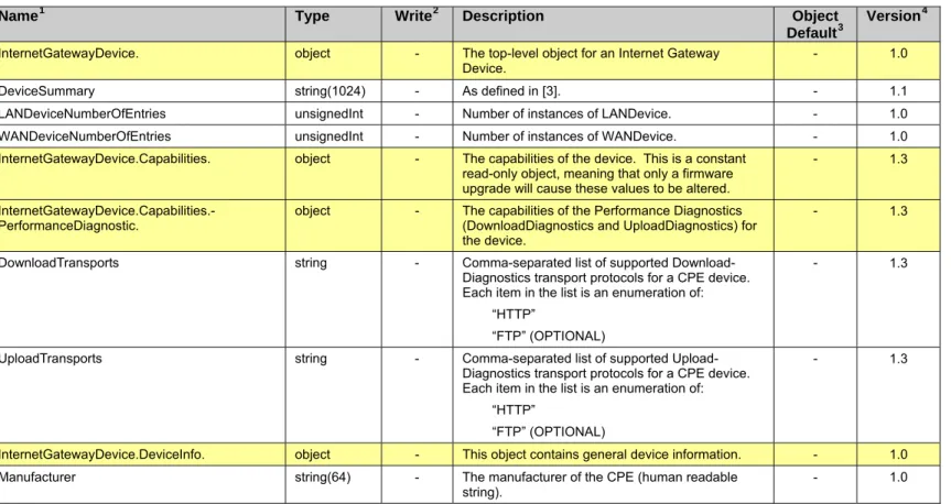
Table 2 defines version 1.4 of the InternetGatewayDevice data model. This definition is a superset of
previously defined versions, 1.3, 1.2, 1.1 and 1.0. The table lists the objects defined for an Internet
Gateway Device, and the corresponding parameters within those objects.
For a given implementation of this data model, the CPE MUST indicate support for the highest version
number of any object or parameter that it supports. For example, even if the CPE supports only a single
parameter that was introduced in version 1.4, then it would have to indicate support for version 1.4. The
version number associated with each object and parameter is shown in the Version column of Table 2.
Table 2 – Definition of InternetGatewayDevice:1
Name
1Type
Write
2Description
Object
Default
3Version
4InternetGatewayDevice. object - The top-level object for an Internet Gateway
Device.
- 1.0
DeviceSummary string(1024) - As defined in [3]. - 1.1
LANDeviceNumberOfEntries unsignedInt - Number of instances of LANDevice. - 1.0
WANDeviceNumberOfEntries unsignedInt - Number of instances of WANDevice. - 1.0
InternetGatewayDevice.Capabilities. object - The capabilities of the device. This is a constant
read-only object, meaning that only a firmware upgrade will cause these values to be altered.
- 1.3
InternetGatewayDevice.Capabilities.-PerformanceDiagnostic. object - The capabilities of the Performance Diagnostics (DownloadDiagnostics and UploadDiagnostics) for the device.
- 1.3
DownloadTransports string - Comma-separated list of supported
Download-Diagnostics transport protocols for a CPE device. Each item in the list is an enumeration of:
“HTTP”
“FTP” (OPTIONAL)
- 1.3
UploadTransports string - Comma-separated list of supported
Upload-Diagnostics transport protocols for a CPE device. Each item in the list is an enumeration of:
“HTTP”
“FTP” (OPTIONAL)
- 1.3
InternetGatewayDevice.DeviceInfo. object - This object contains general device information. - 1.0
Manufacturer string(64) - The manufacturer of the CPE (human readable
string). - 1.0
1
The full name of a Parameter is the concatenation of the object name shown in the yellow header with the
individual Parameter name.
2
“W” indicates the parameter MAY be writable (if “W” is not present, the parameter is defined as
read-only). For an object, “W” indicates object instances can be Added or Deleted.
3
The default value of the parameter on creation of an object instance via TR-069. If the default value is an
empty string, this is represented by the symbol <Empty>. A hyphen indicates that no default value is
specified. For a parameter in which no default value is specified, on creation of a parent object instance,
Internet Gateway Device Data Model for TR-069
TR-098 Amendment 2
1
Name
Type
Write
2Description
Object
Version
4Default
3ManufacturerOUI string(6) - Organizationally unique identifier of the device
manufacturer. Represented as a six hexadecimal-digit value using all upper-case letters and including any leading zeros. The value MUST be a valid OUI as defined in [5].
This value MUST remain fixed over the lifetime of the device, including across firmware updates.
- 1.0
ModelName string(64) - Model name of the CPE (human readable string). - 1.0
Description string(256) - A full description of the CPE device (human
readable string).
- 1.0
ProductClass string(64) - Identifier of the class of product for which the serial
number applies. That is, for a given manufacturer, this parameter is used to identify the product or class of product over which the SerialNumber parameter is unique.
This value MUST remain fixed over the lifetime of the device, including across firmware updates.
- 1.0
SerialNumber string(64) - Serial number of the CPE.
This value MUST remain fixed over the lifetime of the device, including across firmware updates.
- 1.0
HardwareVersion string(64) - A string identifying the particular CPE model and
version.
- 1.0
SoftwareVersion string(64) - A string identifying the software version currently
installed in the CPE.
To allow version comparisons, this element SHOULD be in the form of dot-delimited integers, where each successive integer represents a more minor category of variation. For example, 3.0.21 where the components mean: Major.Minor.Build.
- 1.0
ModemFirmwareVersion string(64) - A string identifying the version of the modem
firmware currently installed in the CPE. This is applicable only when the modem firmware is separable from the overall CPE software.
- 1.0
EnabledOptions string(1024) - Comma-separated list of the OptionName of each
Option that is currently enabled in the CPE. The OptionName of each is identical to the OptionName element of the OptionStruct described in [2]. Only those options are listed whose State indicates the option is enabled.
- 1.0
AdditionalHardwareVersion string(64) - A comma-separated list of any additional versions.
Represents any additional hardware version information the vendor might wish to supply.
- 1.0
AdditionalSoftwareVersion string(64) - A comma-separated list of any additional versions.
Represents any additional software version information the vendor might wish to supply.
- 1.0
SpecVersion string(16) - Represents the version of the specification
implemented by the device. Currently 1.0 is the only available version. The value of this parameter MUST equal “1.0”.
This parameter is DEPRECATED because its value is fixed and it therefore serves no purpose. However, it is a Forced Inform parameter and therefore cannot be OBSOLETED.
Internet Gateway Device Data Model for TR-069
TR-098 Amendment 2
1
Name
Type
Write
2Description
Object
Version
4Default
3ProvisioningCode string(64) W Identifier of the primary service provider and other
provisioning information, which MAY be used by the ACS to determine service provider-specific customization and provisioning parameters. If non-empty, this argument SHOULD be in the form of a hierarchical descriptor with one or more nodes specified. Each node in the hierarchy is represented as a 4-character sub-string, containing only numerals or upper-case letters. If there is more than one node indicated, each node is separated by a "." (dot). Examples: “TLCO” or “TLCO.GRP2”.
- 1.0
UpTime unsignedInt - Time in seconds since the CPE was last restarted. - 1.0
FirstUseDate dateTime - Date and time in UTC that the CPE first both
successfully established an IP-layer network connection and acquired an absolute time reference using NTP or equivalent over that network connection. The CPE MAY reset this date after a factory reset.
If NTP or equivalent is not available, this parameter, if present, SHOULD be set to the Unknown Time value.
- 1.0
DeviceLog string(32K) - Vendor-specific log(s). - 1.0
VendorConfigFileNumberOfEntries unsignedInt - Number of instances of VendorConfigFile. - 1.0
InternetGatewayDevice.DeviceInfo.Vendor-ConfigFile.{i}. object - Every instance of this object is a Vendor Configuration File, and contains parameters associated with the Vendor Configuration File. This table of Vendor Configuration Files is for information only and does not allow the ACS to operate on these files in any way.
Whenever the CPE successfully downloads a configuration file as a result of the Download RPC with the FileType argument of “3 Vendor
Configuration File”, the CPE MUST update this table. If the name of the file (determined as described in the definition of the Name parameter) differs from that of any existing instance, then the CPE MUST create a new instance to represent this file. If instead, the name of the file is identical to that of an existing instance, then the CPE MUST update the content of the existing instance with the new version, date, and (optionally) description of the file.
- 1.0
Name string(64) - Name of the vendor configuration file.
If the CPE is able to obtain the name of the configuration file from the file itself, then the value of this parameter MUST be set to that name. Otherwise, if the CPE can extract the file name from the URL used to download the configuration file, then the value of this parameter MUST be set to that name.
Otherwise, the value of this parameter MUST be set to the value of the TargetFileName argument of the Download RPC used to download this configuration file.
Internet Gateway Device Data Model for TR-069
TR-098 Amendment 2
1
Name
Type
Write
2Description
Object
Version
4Default
3Version string(16) - A string identifying the configuration file version
currently used in the CPE.
If the CPE is able to obtain the version of the configuration file from the file itself, then the value of this parameter MUST be set to the obtained value.
Otherwise, the value of this parameter MUST be empty.
- 1.0
Date dateTime - Date and time when the content of the current
version of this vendor configuration file was first applied by the CPE.
- 1.0
Description string(256) - A description of the vendor configuration file
(human-readable string).
- 1.0
InternetGatewayDevice.DeviceConfig. object - This object contains general configuration
parameters.
- 1.0
PersistentData string(256) W Arbitrary user data that MUST persist across CPE
reboots.
- 1.0
ConfigFile string(32K) W A dump of the currently running configuration on
the CPE. This parameter enables the ability to backup and restore the last known good state of the CPE. It returns a vendor-specific document that defines the state of the CPE. The document MUST be capable of restoring the CPE’s state when written back to the CPE using
SetParameterValues.
An alternative to this parameter, e.g. when the configuration file is larger than the parameter size limit, is to use the Upload and Download RPCs with a FileType of “1 Vendor Configuration File”.
- 1.0
InternetGatewayDevice.ManagementServer. object - This object contains parameters relating to the
CPE’s association with an ACS.
- 1.0
EnableCWMP boolean W Enables and disables the CPE’s support for
CWMP.
False means that CWMP support in the CPE is disabled, in which case the device MUST NOT send any Inform messages to the ACS or accept any Connection Request notifications from the ACS.
True means that CWMP support on the CPE is enabled.
The factory default value MUST be True. The subscriber can re-enable the CPE’s CWMP support either by performing a factory reset or by using a LAN-side protocol to change the value of this parameter back to True.
- 1.4
URL string(256) W URL, as defined in [8], for the CPE to connect to
the ACS using the CPE WAN Management Protocol.
This parameter MUST be in the form of a valid HTTP or HTTPS URL [6].
The “host” portion of this URL is used by the CPE for validating the ACS certificate when using SSL or TLS.
Note that on a factory reset of the CPE, the value of this parameter might be reset to its factory value. If an ACS modifies the value of this parameter, it SHOULD be prepared to accommodate the situation that the original value is restored as the result of a factory reset.
Internet Gateway Device Data Model for TR-069
TR-098 Amendment 2
1
Name
Type
Write
2Description
Object
Version
4Default
3Username string(256) W Username used to authenticate the CPE when
making a connection to the ACS using the CPE WAN Management Protocol.
This username is used only for HTTP-based authentication of the CPE.
Note that on a factory reset of the CPE, the value of this parameter might be reset to its factory value. If an ACS modifies the value of this parameter, it SHOULD be prepared to accommodate the situation that the original value is restored as the result of a factory reset.
- 1.0
Password string(256) W Password used to authenticate the CPE when
making a connection to the ACS using the CPE WAN Management Protocol.
This password is used only for HTTP-based authentication of the CPE.
When read, this parameter returns an empty string, regardless of the actual value.
Note that on a factory reset of the CPE, the value of this parameter might be reset to its factory value. If an ACS modifies the value of this parameter, it SHOULD be prepared to accommodate the situation that the original value is restored as the result of a factory reset.
- 1.0
PeriodicInformEnable boolean W Whether or not the CPE MUST periodically send
CPE information to the ACS using the Inform method call.
- 1.0
PeriodicInformInterval unsignedInt
[1:] W The duration in seconds of the interval for which the CPE MUST attempt to connect with the ACS and call the Inform method if PeriodicInformEnable is True.
- 1.0
PeriodicInformTime dateTime W An absolute time reference in UTC to determine
when the CPE will initiate the periodic Inform method calls. Each Inform call MUST occur at this reference time plus or minus an integer multiple of the PeriodicInformInterval.
PeriodicInformTime is used only to set the “phase” of the periodic Informs. The actual value of PeriodicInformTime can be arbitrarily far into the past or future.
For example, if PeriodicInformInterval is 86400 (a day) and if PeriodicInformTime is set to UTC midnight on some day (in the past, present, or future) then periodic Informs will occur every day at UTC midnight. These MUST begin on the very next midnight, even if PeriodicInformTime refers to a day in the future.
The Unknown Time value defined in section 2.2 indicates that no particular time reference is specified. That is, the CPE MAY locally choose the time reference, and needs only to adhere to the specified PeriodicInformInterval.
If absolute time is not available to the CPE, its periodic Inform behavior MUST be the same as if the PeriodicInformTime parameter was set to the Unknown Time value.
Internet Gateway Device Data Model for TR-069
TR-098 Amendment 2
1
Name
Type
Write
2Description
Object
Version
4Default
3ParameterKey string(32) - ParameterKey provides the ACS a reliable and
extensible means to track changes made by the ACS. The value of ParameterKey MUST be equal to the value of the ParameterKey argument from the most recent successful SetParameterValues, AddObject, or DeleteObject method call from the ACS.
The CPE MUST set ParameterKey to the value specified in the corresponding method arguments if and only if the method completes successfully and no fault response is generated. If a method call does not complete successfully (implying that the changes requested in the method did not take effect), the value of ParameterKey MUST NOT be modified.
The CPE MUST only modify the value of ParameterKey as a result of SetParameterValues, AddObject, DeleteObject, or due to a factory reset. On factory reset, the value of ParameterKey MUST be set to empty.
- 1.0
ConnectionRequestURL string(256) - HTTP URL, as defined in [8], for an ACS to make a
Connection Request notification to the CPE. In the form:
http://host:port/path
The “host” portion of the URL MAY be the IP address for the management interface of the CPE in lieu of a host name.
- 1.0
ConnectionRequestUsername string(256) W Username used to authenticate an ACS making a
Connection Request to the CPE.
- 1.0
ConnectionRequestPassword string(256) W Password used to authenticate an ACS making a
Connection Request to the CPE.
When read, this parameter returns an empty string, regardless of the actual value.
- 1.0
UpgradesManaged boolean W Indicates whether or not the ACS will manage
upgrades for the CPE. If True, the CPE SHOULD NOT use other means other than the ACS to seek out available upgrades. If False, the CPE MAY use other means for this purpose.
Note that an autonomous upgrade (reported via an "10 AUTONOMOUS TRANSFER COMPLETE” Inform Event code) SHOULD be regarded as a managed upgade if it is performed according to ACS-specified policy.
- 1.0
KickURL string(256) - Present only for a CPE that supports the Kicked
RPC method.
LAN-accessible URL, as defined in [8], from which the CPE can be “kicked” to initiate the Kicked RPC method call. MUST be an absolute URL including a host name or IP address as would be used on the LAN side of the CPE.
- 1.0
DownloadProgressURL string(256) - Present only for a CPE that provides a LAN-side
web page to show progress during a file download. LAN-accessible URL, as defined in [8], to which a web-server associated with the ACS MAY redirect a user’s browser on initiation of a file download to observer the status of the download.
Internet Gateway Device Data Model for TR-069
TR-098 Amendment 2
1
Name
Type
Write
2Description
Object
Version
4Default
3DefaultActiveNotificationThrottle unsignedInt W This parameter is used to control throttling of active
notifications sent by the CPE to the ACS. It defines the minimum number of seconds that the CPE MUST wait since the end of the last session with the ACS before establishing a new session for the purpose of delivering an active notification. In other words, if CPE needs to establish a new session with the ACS for the sole purpose of delivering an active notification, it MUST delay establishing such a session as needed to ensure that the minimum time since the last session completion has been met.
The time is counted since the last successfully completed session, regardless of whether or not it was used for active notifications or other purposes. However, if connection to the ACS is established for purposes other than just delivering active notifications, including for the purpose of retrying a failed session, such connection MUST NOT be delayed based on this parameter value, and the pending active notifications MUST be
communicated during that connection.
The time of the last session completion does not need to be tracked across reboots.
- 1.4
UDPConnectionRequestAddress string(256) - Address and port to which an ACS MAY send a
UDP Connection Request to the CPE (see Annex G of [2]).
This parameter is represented in the form of an Authority element as defined in [8]. The value MUST be in one of the following two forms:
host:port host
When STUNEnable is True, the “host” and “port” portions of this parameter MUST represent the public address and port corresponding to the NAT binding through which the ACS can send UDP Connection Request messages (once this information is learned by the CPE through the use of STUN).
When STUNEnable is False, the “host” and “port” portions of the URL MUST represent the local IP address and port on which the CPE is listening for UDP Connection Request messages.
The second form of this parameter MAY be used only if the port value is equal to “80”.
- 1.2
UDPConnectionRequestAddressNotification-Limit
unsignedInt W The minimum time, in seconds, between Active
Notifications resulting from changes to the UDP-ConnectionRequestAddress (if Active Notification is enabled).
- 1.2
STUNEnable boolean W Enables or disables the use of STUN by the CPE.
This applies only to the use of STUN in association with the ACS to allow UDP Connection Requests.
- 1.2
STUNServerAddress string(256) W Host name or IP address of the STUN server for
the CPE to send Binding Requests if STUN is enabled via STUNEnable.
If empty and STUNEnable is True, the CPE MUST use the address of the ACS extracted from the host
Internet Gateway Device Data Model for TR-069
TR-098 Amendment 2
1
Name
Type
Write
2Description
Object
Version
4Default
3STUNServerPort unsignedInt [0:65535]
W Port number of the STUN server for the CPE to
send Binding Requests if STUN is enabled via STUNEnable.
By default, this SHOULD be the equal to the default STUN port, 3478.
- 1.2
STUNUsername string(256) W If non-empty, the value of the STUN USERNAME
attribute to be used in Binding Requests (only if message integrity has been requested by the STUN server).
If empty, the CPE MUST NOT send STUN Binding Requests with message integrity.
- 1.2
STUNPassword string(256) W The value of the STUN Password to be used in
computing the MESSAGE-INTEGRITY attribute to be used in Binding Requests (only if message integrity has been requested by the STUN server). When read, this parameter returns an empty string, regardless of the actual value.
- 1.2
STUNMaximumKeepAlivePeriod int[-1:] W If STUN Is enabled, the maximum period, in
seconds, that STUN Binding Requests MUST be sent by the CPE for the purpose of maintaining the binding in the Gateway. This applies specifically to Binding Requests sent from the UDP Connection Request address and port.
A value of -1 indicates that no maximum period is specified.
- 1.2
STUNMinimumKeepAlivePeriod unsignedInt W If STUN Is enabled, the minimum period, in
seconds, that STUN Binding Requests can be sent by the CPE for the purpose of maintaining the binding in the Gateway. This limit applies only to Binding Requests sent from the UDP Connection Request address and port, and only those that do not contain the BINDING-CHANGE attribute. This limit does not apply to retransmissions following the procedures defined in [9].
- 1.2
NATDetected boolean - When STUN is enabled, this parameter indicates
whether or not the CPE has detected address and/or port mapping in use.
A True value indicates that the received MAPPED-ADDRESS in the most recent Binding Response differs from the CPE’s source address and port. When STUNEnable is False, this value MUST be False.
- 1.2
ManageableDeviceNumberOfEntries unsignedInt - Number of entries in the ManageableDevice table. - 1.2
ManageableDeviceNotificationLimit unsignedInt W The minimum time, in seconds, between Active
Notifications resulting from changes to the ManageableDeviceNumberOfEntries (if Active Notification is enabled).
- 1.2
InternetGatewayDevice.ManagementServer.-ManageableDevice.{i}.
object - Each entry in this table corresponds to a distinct
LAN Device that supports Device-Gateway Association according to Annex F of [2] as indicated by the presence of the DHCP option specified in that Annex.
- 1.2
ManufacturerOUI string(6) - Organizationally unique identifier of the Device
manufacturer as provided to the Gateway by the Device. Represented as a six hexadecimal-digit value using all upper-case letters and including any leading zeros. The value MUST be a valid OUI as defined in [5].
- 1.2
SerialNumber string(64) - Serial number of the Device as provided to the
Internet Gateway Device Data Model for TR-069
TR-098 Amendment 2
1
Name
Type
Write
2Description
Object
Version
4Default
3ProductClass string(64) - Identifier of the class of product for which the
Device’s serial number applies as provided to the Gateway by the Device.
If the Device does not provide a Product Class, then this parameter MUST be left empty.
- 1.2
Host string(1024) - Comma-separated list of the full path names of all
Host table entries, whether active or inactive, that correspond to this physical LAN Device.
As such entries are added to or removed from the Host tables, the value of this parameter MUST be updated accordingly. For example: “InternetGatewayDevice.LANDevice.1.Hosts. Host.1,InternetGatewayDevice.LANDevice.1. Hosts.Host.5” - 1.4
InternetGatewayDevice.Time. object - This object contains parameters relating an NTP or
SNTP time client in the CPE.
- 1.0
Enable boolean W Enables or disables the NTP or SNTP time client. - 1.4
Status string - Status of Time support on the CPE. Enumeration
of: “Disabled” “Unsynchronized” “Synchronized” “Error_FailedToSynchronize” “Error” (OPTIONAL)
The “Unsynchronized” value indicates that the CPE’s absolute time has not yet been set. The “Synchronized” value indicates that the CPE has acquired accurate absolute time; its current time is accurate.
The “Error_FailedToSynchronize” value indicates that the CPE failed to acquire accurate absolute time; its current time is not accurate.
The “Error” value MAY be used by the CPE to indicate a locally defined error condition.
- 1.4
NTPServer1 string(64) W First NTP timeserver. Either a host name or IP
address. - 1.0
NTPServer2 string(64) W Second NTP timeserver. Either a host name or IP
address.
- 1.0
NTPServer3 string(64) W Third NTP timeserver. Either a host name or IP
address.
- 1.0
NTPServer4 string(64) W Fourth NTP timeserver. Either a host name or IP
address.
- 1.0
NTPServer5 string(64) W Fifth NTP timeserver. Either a host name or IP
address.
- 1.0
CurrentLocalTime dateTime - The current date and time in the CPE’s local time
zone.
Internet Gateway Device Data Model for TR-069
TR-098 Amendment 2
1
Name
Type
Write
2Description
Object
Version
4Default
3LocalTimeZone string(6) W The local time zone offset from UTC, ignoring
daylight savings time adjustments, in the form: +hh:mm
-hh:mm
For example, this will always be “-08:00” for California, “+00:00” or “-00:00” for the United Kingdom, and “+01:00” for France.
This parameter is OBSOLETED because the information that it represents is fully covered by LocalTimeZoneName.
- 1.0
LocalTimeZoneName string(64) W Name of the local time zone (human readable
string).
The name SHOULD be encoded according to IEEE 1003.1 (POSIX). The following is an example value:
“EST+5EDT,M4.1.0/2,M10.5.0/2”
- 1.0
DaylightSavingsUsed boolean W Whether or not daylight savings time is in use in
the CPE’s local time zone.
This parameter is OBSOLETED because the information that it represents is fully covered by LocalTimeZoneName.
- 1.0
DaylightSavingsStart dateTime W Current local date and time at which the switch to
daylight savings time occurs. If daylight savings time is not used, this value is ignored.
This parameter is OBSOLETED because the information that it represents is fully covered by LocalTimeZoneName.
- 1.0
DaylightSavingsEnd dateTime W Current local date and time at which the switch
from daylight savings time will occur. If daylight savings time is not used, this value is ignored. This parameter is OBSOLETED because the information that it represents is fully covered by LocalTimeZoneName.
- 1.0
InternetGatewayDevice.UserInterface. object - This object contains parameters relating to the user
interface of the CPE.
- 1.0
UserDatabaseSupported boolean - Present only if the CPE provides a
password-protected LAN-side user interface.
Indicates whether or not the CPE supports a user database that provides per-user passwords that can be used for accessing the local user interface.
- 1.4
SharedPassword boolean W Present only if the CPE provides a
password-protected LAN-side user interface.
Indicates whether or not a single shared password MUST protect the local user interface, or whether per-user passwords can be used.
If either UserDatabaseSupported or Password-UserSelectable is False, the CPE MUST ignore the value of this parameter.
- 1.4
PasswordRequired boolean W Present only if the CPE provides a
password-protected LAN-side user interface.
Indicates whether or not the local user interface MUST require a password to be chosen by the user. If False, the choice of whether or not a password is used is left to the user.
Internet Gateway Device Data Model for TR-069
TR-098 Amendment 2
1
Name
Type
Write
2Description
Object
Version
4Default
3PasswordUserSelectable boolean W Present only if the CPE provides a
password-protected LAN-side user interface and supports LAN-side Auto-Configuration.
Indicates whether or not a password to protect the local user interface of the CPE MAY be selected by the user directly, or MUST be equal to the
password used by the LAN-side Auto-Configuration protocol.
- 1.0
UpgradeAvailable boolean W Indicates that a CPE upgrade is available, allowing
the CPE to display this information to the user.
- 1.0
WarrantyDate dateTime W Indicates the date and time in UTC that the
warranty associated with the CPE is to expire.
- 1.0
ISPName string(64) W The name of the customer’s ISP. - 1.0
ISPHelpDesk string(32) W The help desk phone number of the ISP. - 1.0
ISPHomePage string(256) W The URL of the ISP’s home page. - 1.0
ISPHelpPage string(256) W The URL of the ISP’s on-line support page. - 1.0
ISPLogo base64
(5460)
W Base64 encoded GIF or JPEG image. The binary
image is constrained to 4095 bytes or less.
- 1.0 ISPLogoSize unsignedInt
[0:4095]
W Un-encoded binary image size in bytes.
If ISPLogoSize input value is 0 then the ISPLogo is cleared.
ISPLogoSize can also be used as a check to verify correct transfer and conversion of Base64 string to image size.
- 1.0
ISPMailServer string(256) W The URL of the ISP’s mail server. - 1.0
ISPNewsServer string(256) W The URL of the ISP’s news server. - 1.0
TextColor string(6) W The color of text on the GUI screens in RGB
hexidecimal notation (e.g., FF0088).
- 1.0
BackgroundColor string(6) W The color of the GUI screen backgrounds in RGB
hexidecimal notation (e.g., FF0088).
- 1.0
ButtonColor string(6) W The color of buttons on the GUI screens in RGB
hexidecimal notation (e.g., FF0088).
- 1.0
ButtonTextColor string(6) W The color of text on buttons on the GUI screens in
RGB hexidecimal notation (e.g., FF0088).
- 1.0
AutoUpdateServer string(256) W The server the CPE can check to see if an update
is available for direct download to it. This MUST NOT be used by the CPE if the InternetGateway-Device.ManagementServer.UpgradesManaged parameter is True.
- 1.0
UserUpdateServer string(256) W The server where a user can check via a web
browser if an update is available for download to a PC. This MUST NOT be used by the CPE if the InternetGatewayDevice.ManagementServer.-UpgradesManaged parameter is True.
- 1.0
ExampleLogin string(40) W An example of a correct login, according to
ISP-specific rules. - 1.0
ExamplePassword string(30) W An example of a correct password, according to
ISP-specific rules.
- 1.0
AvailableLanguages string(256) - Comma-separated list of user-interface languages
that are available, where each language is specified according to RFC 3066 [40].
- 1.4
CurrentLanguage string(16) W Current user-interface language, specified
according to RFC 3066 [40].
Internet Gateway Device Data Model for TR-069
TR-098 Amendment 2
1
Name
Type
Write
2Description
Object
Version
4Default
3InternetGatewayDevice.CaptivePortal. object - This object contains parameters relating to the
captive portal configuration on the CPE.
The captive portal configuration defines the CPE’s WAN-destined HTTP (port 80) traffic redirect behavior.
When the captive portal is disabled, WAN-destined HTTP (port 80) traffic MUST be permitted to all destinations.
When the captive portal is enabled, WAN-destined HTTP (port 80) traffic MUST be permitted only to destinations listed in the AllowedList; traffic to all other destinations MUST be redirected to the CaptivePortalURL.
- 1.4
Enable boolean W Enables or disables the captive portal. - 1.4
Status string - Indicates the status of the captive portal.
Enumeration of: “Disabled” “Enabled” “Error_URLEmpty” (CaptivePortalURL is empty) “Error” (OPTIONAL)
The “Error” value MAY be used by the CPE to indicate a locally defined error condition.
- 1.4
AllowedList string (10000)
W Comma-separated list of IP addresses to which
HTTP (port 80) traffic MUST always be permitted, regardless of whether the captive portal is enabled. Each entry in the list MUST be either an IP address or an IP subnet specified using variable length subnet mask (VLSM) syntax.
An IP subnet is specified as an IP address followed (with no intervening white space) by “/n”, where n is an integer in the range 0-32; this is equivalent to a subnet mask consisting of n 1s followed by 32 minus n 0s.
For example, 1.2.3.4 specifies a single IP address, and 1.2.3.4/24 specifies a class C subnet with subnet mask 255.255.255.0.
The maximum length of a single entry (plus comma) is 19 characters so 10000 bytes is sufficient for more than 500 IP addresses and/or IP subnets.
- 1.4
CaptivePortalURL string(2000) W Captive portal URL to which WAN-destined HTTP
(port 80) traffic to destinations not listed in the AllowedList will be redirected.
The captive portal URL MUST be an HTTP (not HTTPS) URL.
The CPE MUST permit the captive portal URL to be set to an empty string, which has the effect of disabling the captive portal (if Enable is True and the captive portal URL is an empty string, Status MUST be “Error_URLEmpty”).
- 1.4
InternetGatewayDevice.Layer3Forwarding. object - This object allows the handling of the routing and
forwarding configuration of the device.
- 1.0
DefaultConnectionService string(256) W Specifies the default WAN interface. The content
is the full hierarchical parameter name of the default layer 3 connection object. Example: “InternetGatewayDevice.WANDevice.1.WAN-ConnectionDevice.2.WANPPPConnection.1”.
Internet Gateway Device Data Model for TR-069
TR-098 Amendment 2
1
Name
Type
Write
2Description
Object
Version
4Default
3ForwardNumberOfEntries unsignedInt - Number of forwarding instances. - 1.0
InternetGatewayDevice.Layer3Forwarding.-Forwarding.{i}.
object W Layer 3 forwarding table.
In addition to statically configured routes, this table MUST include dynamic routes learned through layer 3 routing protocols, including RIP, OSPF, DHCP, and IPCP. The CPE MAY reject attempts to delete or modify a dynamic route entry. For each incoming packet, the layer 3 forwarding decision is conceptually made as follows:
• Only table entries with a matching ForwardingPolicy are considered, i.e. those that either do not specify a ForwardingPolicy, or else specify a ForwardingPolicy that matches that of the incoming packet.
• For the remaining table entries, those for which the source address/mask matches are sorted by longest prefix, i.e. with the most specific networks first (an
unspecified source address is a wild-card and always matches, with a prefix length of zero).
• For the remaining table entries, those for which the destination address/mask matches are sorted by longest prefix, i.e. with the most specific networks first (an unspecified destination address is a wild-card and always matches, with a prefix length of zero).
• The first of the remaining table entries is applied to the packet.
- 1.0
Enable boolean W Enables or disables the forwarding entry. On
creation, an entry is disabled by default.
False 1.0
Status string - Indicates the status of the forwarding entry.
Enumeration of: “Disabled” “Enabled”
“Error” (OPTIONAL)
The “Error” value MAY be used by the CPE to indicate a locally defined error condition.
“Disabled” 1.0
StaticRoute boolean - If True, this route is a Static route. True 1.4
Type string W Indicates the type of route. Enumeration of:
“Default” “Network” “Host”
This parameter is DEPRECATED because its value could conflict with DestIPAddress and/or DestSubnetMask.
“Host” 1.0
DestIPAddress string W Destination address. An empty string or a value of
“0.0.0.0” indicates no destination address is specified.
A Forwarding table entry for which DestIPAddress
Internet Gateway Device Data Model for TR-069
TR-098 Amendment 2
1
Name
Type
Write
2Description
Object
Version
4Default
3DestSubnetMask string W Destination subnet mask. An empty string or a
value of “0.0.0.0” indicates no destination subnet mask is specified.
If a destination subnet mask is specified, the DestSubnetMask is ANDed with the destination address before comparing with the DestIPAddress. Otherwise, the full destination address is used as is.
A Forwarding table entry for which DestIPAddress and DestSubnetMask are both empty or “0.0.0.0” is a default route.
<Empty> 1.0
SourceIPAddress string W Source address. An empty string or a value of
“0.0.0.0” indicates no source address is specified.
<Empty> 1.0
SourceSubnetMask string W Source subnet mask. An empty string or a value of
“0.0.0.0” indicates no source subnet mask is specified.
If a source subnet mask is specified, the SourceSubnetMask is ANDed with the source address before comparing with the
SourceIPAddress. Otherwise, the full source address is used as is.
<Empty> 1.0
ForwardingPolicy int[-1:] W Identifier of a set of classes or flows that have the
corresponding ForwardingPolicy value as defined in the QueueManagement object.
A value of -1 indicates no ForwardingPolicy is specified.
If specified, this forwarding entry is to apply only to traffic associated with the specified classes and flows.
-1 1.0
GatewayIPAddress string W IP address of the gateway.
Only one of GatewayIPAddress and Interface SHOULD be configured for a route.
If both are configured, GatewayIPAddress and Interface MUST be consistent with each other.
<Empty> 1.0
Interface string(256) W Specifies the egress interface associated with this
entry. The content is the full hierarchical parameter name of the layer 3 connection object. Example: “InternetGatewayDevice.WANDevice.1.WAN-ConnectionDevice.2.WANPPPConnection.1”. Only one of GatewayIPAddress and Interface SHOULD be configured for a route.
If both are configured, GatewayIPAddress and Interface MUST be consistent with each other. For a route that was configured by setting GatewayIPAddress but not Interface, read access to Interface MUST return the full hierarchical parameter name for the route’s egress interface.
- 1.0
ForwardingMetric int[-1:] W Forwarding metric. A value of -1 indicates this
metric is not used.
-1 1.0 MTU unsignedInt