TR-181
Device Data Model for TR-069
Issue: 2 Amendment 2 Issue Date: February 2011Notice
The Broadband Forum is a non-profit corporation organized to create guidelines for broadband network system development and deployment. This Broadband Forum Technical Report has been approved by members of the Forum. This Broadband Forum Technical Report is not
binding on the Broadband Forum, any of its members, or any developer or service provider. This Broadband Forum Technical Report is subject to change, but only with approval of members of the Forum. This Technical Report is copyrighted by the Broadband Forum, and all rights are reserved. Portions of this Technical Report may be copyrighted by Broadband Forum members. This Broadband Forum Technical Report is provided AS IS, WITH ALL FAULTS. ANY PERSON HOLDING A COPYRIGHT IN THIS BROADBAND FORUM TECHNICAL REPORT, OR ANY PORTION THEREOF, DISCLAIMS TO THE FULLEST EXTENT PERMITTED BY LAW ANY REPRESENTATION OR WARRANTY, EXPRESS OR IMPLIED, INCLUDING, BUT NOT LIMITED TO, ANY WARRANTY:
(A) OF ACCURACY, COMPLETENESS, MERCHANTABILITY, FITNESS FOR A PARTICULAR PURPOSE, NON-INFRINGEMENT, OR TITLE;
(B) THAT THE CONTENTS OF THIS BROADBAND FORUM TECHNICAL REPORT ARE SUITABLE FOR ANY PURPOSE, EVEN IF THAT PURPOSE IS KNOWN TO THE COPYRIGHT HOLDER;
(C) THAT THE IMPLEMENTATION OF THE CONTENTS OF THE TECHNICAL REPORT WILL NOT INFRINGE ANY THIRD PARTY PATENTS, COPYRIGHTS, TRADEMARKS OR OTHER RIGHTS.
By using this Broadband Forum Technical Report, users acknowledge that implementation may require licenses to patents. The Broadband Forum encourages but does not require its members to identify such patents. For a list of declarations made by Broadband Forum member
companies, please see http://www.broadband-forum.org. No assurance is given that licenses to patents necessary to implement this Technical Report will be available for license at all or on reasonable and non-discriminatory terms.
ANY PERSON HOLDING A COPYRIGHT IN THIS BROADBAND FORUM TECHNICAL REPORT, OR ANY PORTION THEREOF, DISCLAIMS TO THE FULLEST EXTENT
PERMITTED BY LAW (A) ANY LIABILITY (INCLUDING DIRECT, INDIRECT, SPECIAL, OR CONSEQUENTIAL DAMAGES UNDER ANY LEGAL THEORY) ARISING FROM OR RELATED TO THE USE OF OR RELIANCE UPON THIS TECHNICAL REPORT; AND (B) ANY OBLIGATION TO UPDATE OR CORRECT THIS TECHNICAL REPORT.
Broadband Forum Technical Reports may be copied, downloaded, stored on a server or otherwise re-distributed in their entirety only, and may not be modified without the advance written permission of the Broadband Forum.
Issue History
Issue Number Issue Date Issue Editor Changes
Issue 2 May 2010 Paul Sigurdson, Broadband Forum William Lupton, 2Wire
Original. Defines version 2.0 of the TR-069 Device data model (Device:2.0). Issue 2
Amendment 1
November 2010
Paul Sigurdson, Broadband Forum William Lupton, 2Wire
Added support for Software Module Management in the data model (no change to this document). Defines version 2.1 of the TR-069 Device data model (Device:2.1).
Issue 2 Amendment 2
February 2011 Paul Sigurdson, Broadband Forum William Lupton, Pace
Added support for IPv6 and Firewall in the data model (added IPv6 and Firewall Appendices to this document). Defines version 2.2 of the TR-069 Device data model (Device:2.2).
Comments or questions about this Broadband Forum Technical Report should be directed to
Editors William Lupton Pace
Paul Sigurdson Broadband Forum
BroadbandHome™
Working Group Chairs Greg Bathrick Heather Kirksey PMC-Sierra Alcatel-Lucent
Table of Contents
EXECUTIVE SUMMARY ... 8
1 PURPOSE AND SCOPE ... 9
1.1 PURPOSE ... 9
1.2 SCOPE ... 9
2 REFERENCES AND TERMINOLOGY ... 14
2.1 CONVENTIONS ... 14
2.2 REFERENCES ... 14
2.3 DEFINITIONS ... 17
2.4 ABBREVIATIONS ... 18
3 TECHNICAL REPORT IMPACT ... 19
3.1 ENERGY EFFICIENCY ... 19 3.2 IPV6 ... 19 3.3 SECURITY ... 19 4 ARCHITECTURE ... 20 4.1 INTERFACE LAYERS ... 20 4.2 INTERFACE OBJECTS ... 21 4.2.1 Lower Layers ... 23
4.2.2 Administrative and Operational Status ... 24
4.2.3 Stacking and Operational Status ... 25
4.2.4 Vendor-specific Interface Objects ... 25
4.3 INTERFACESTACK TABLE ... 26
5 PARAMETER DEFINITIONS ... 30
ANNEX A: BRIDGING AND QUEUING ... 31
A.1 QUEUING AND BRIDGING MODEL ... 31
A.1.1 Packet Classification ... 31
A.1.1.1 Classification Order ... 32
A.1.1.2 Dynamic Application Specific Classification ... 33
A.1.1.3 Classification Outcome ... 34
A.1.2 Policing ... 34
A.1.3 Queuing and Scheduling ... 34
A.1.4 Bridging ... 35
A.1.4.1 Filtering ... 36
A.1.4.2 Filter Order ... 36
A.2 DEFAULT LAYER 2/3QOSMAPPING ... 37
A.3 URNDEFINITIONS FOR APP AND FLOW TABLES ... 38
A.3.1 App ProtocolIdentifier ... 38
A.3.2 Flow Type ... 38
A.3.3 Flow TypeParameters ... 39
APPENDIX II: USE OF BRIDGING OBJECTS FOR VLAN TAGGING ... 42
II.1 TAGGED LAN TO TAGGED WANTRAFFIC (VLANBRIDGING) ... 43
II.2 TAGGED LAN TO TAGGED WANTRAFFIC (SPECIAL CASE WITH VLANIDTRANSLATION) 44 II.3 UNTAGGED LAN TO TAGGED WANTRAFFIC ... 47
II.4 INTERNALLY GENERATED TO TAGGED WANTRAFFIC ... 48
II.5 OTHER ISSUES ... 49
II.5.1 MORE THAN ONE DOWNSTREAM INTERFACE IN A BRIDGE ... 50
II.5.2 802.1D(RE)-MARKING ... 51
II.5.3 MORE THAN ONE VLANIDTAG ADMITTED ON THE SAME DOWNSTREAM INTERFACE 52 APPENDIX III: WI-FI THEORY OF OPERATION ... 55
III.1 MULTI-RADIO AND MULTI-BAND WI-FI RADIO DEVICES ... 55
III.2 DEFINITIONS ... 55
III.3 NUMBER OF INSTANCES OF WIFI.RADIO OBJECT ... 55
III.4 SUPPORTEDFREQUENCYBANDS AND OPERATINGFREQUENCYBAND ... 56
III.5 BEHAVIOR OF DUAL-BAND RADIOS WHEN OPERATINGFREQUENCYBAND CHANGED ... 56
III.6 SUPPORTEDSTANDARDS AND OPERATINGSTANDARDS ... 56
APPENDIX IV: USE CASES ... 58
IV.1 CREATE A WANCONNECTION ... 58
IV.2 MODIFY A WANCONNECTION ... 58
IV.3 DELETE A WANCONNECTION ... 59
IV.4 DISCOVER WHETHER THE DEVICE IS A GATEWAY ... 59
IV.5 PROVIDE EXTENDED HOME NETWORKING TOPOLOGY VIEW ... 60
IV.6 DETERMINE CURRENT INTERFACES CONFIGURATION ... 60
IV.7 CREATE A WLANCONNECTION ... 60
IV.8 DELETE A WLANCONNECTION ... 61
IV.9 CONFIGURE A DHCPCLIENT AND SERVER ... 61
IV.9.1 DHCPCLIENT CONFIGURATION (ACME DEVICES) ... 61
IV.9.2 DHCPSERVER CONFIGURATION (GATEWAY) ... 61
IV.10 RECONFIGURE AN EXISTING INTERFACE ... 62
APPENDIX V: IPV6 DATA MODELING THEORY OF OPERATION ... 64
V.1 IPV6OVERVIEW ... 64
V.2 DATA MODEL OVERVIEW ... 65
V.3 ENABLING IPV6 ... 68
V.4 CONFIGURING UPSTREAM IPINTERFACES ... 68
V.4.1 CONFIGURATION MESSAGES SENT OUT THE UPSTREAM IPINTERFACE ... 69
V.4.2 IPV6PREFIXES ... 69
V.4.3 IPV6ADDRESSES ... 70
V.5 CONFIGURING DOWNSTREAM IPINTERFACES ... 70
V.5.1 IPV6PREFIXES ... 70
V.5.2 IPV6ADDRESSES ... 71
V.6 DEVICE INTERACTIONS ... 72
V.6.2 MONITORING ... 73
V.7 CONFIGURING IPV6ROUTING AND FORWARDING ... 73
V.8 CONFIGURING IPV6ROUTING AND FORWARDING ... 74
APPENDIX VI: 6RD THEORY OF OPERATION ... 79
VI.1 RFC5969CONFIGURATION PARAMETERS ... 79
VI.2 INTERNAL CONFIGURATION PARAMETERS ... 79
VI.3 IPV4ADDRESS SOURCE ... 79
VI.4 SENDING ALL TRAFFIC TO THE BORDER RELAY SERVER ... 80
VI.5 INTERNAL TREATMENT OF IPV6PACKETS ... 81
APPENDIX VII: DUAL-STACK LITE THEORY OF OPERATION ... 83
VII.1 INTERNAL TREATMENT OF IPV4PACKETS ... 83
List of Figures
Figure 1 – Device:2 Data Model Structure – Overview ... 10
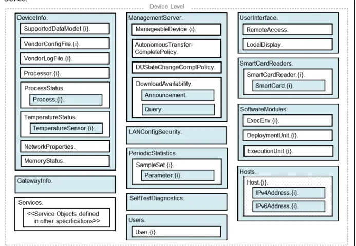
Figure 2 – Device:2 Data Model Structure – Device Level ... 11
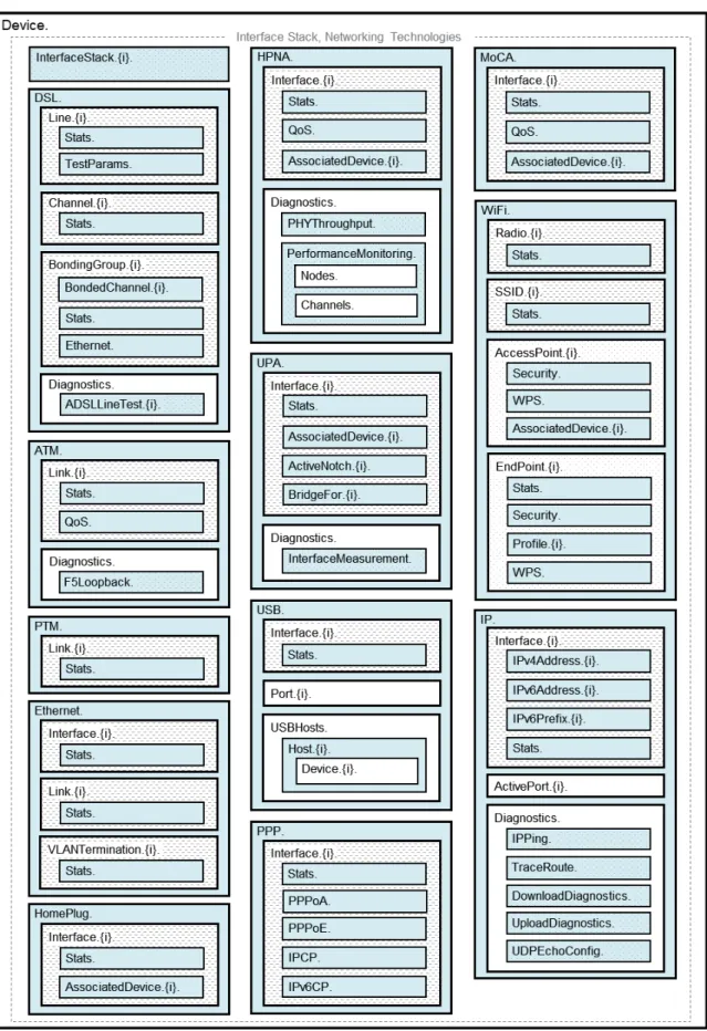
Figure 3 – Device:2 Data Model Structure – Interface Stack and Networking Technologies ... 12
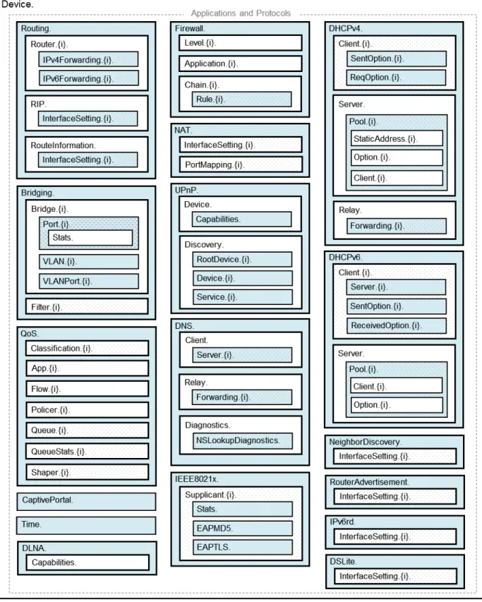
Figure 4 – Device:2 Data Model Structure – Applications and Protocols ... 13
Figure 5 – OSI Layers and Interface Objects ... 21
Figure 6 – Interface LowerLayers ... 24
Figure 7 – Ignoring a Vendor-specific Interface Object in the Stack ... 26
Figure 8 – Ignoring a Vendor-specific Interface Object in the Stack (multiple sub-objects) ... 26
Figure 9 – Simple Router Example (Interfaces Visualized) ... 28
Figure 10 – Queuing Model of a Device ... 31
Figure 11 – Queuing and Scheduling Example for RG ... 41
Figure 12 – Examples of VLAN configuration based on Bridging and VLAN Termination objects ... 42
Figure 13 – Bridge 1 model ... 43
Figure 14 – Bridge 2 model ... 45
Figure 15 – Bridge 3 model ... 47
Figure 16 – VLAN Termination model ... 49
Figure 17 – Bridge 1 model ... 50
Figure 18 – Example of VLAN configuration in a 2 box scenario ... 53
Figure 19 – Bridge 1,2,3 model ... 53
Figure 20 – Relationship of Protocols to Data Model ... 67
Figure 21 – Internal Relationships of IPv6 Addresses and Prefixes ... 68
Figure 22 – Sample 6rd Routing and Forwarding ... 82
Figure 23 – Sample Flow of Upstream Tunneled Traffic through Device QoS ... 82
Figure 24 – Sample DS-Lite Routing and Forwarding ... 84
List of Tables Table 1 – Simple Router Example (InterfaceStack table) ... 27
Table 2 – Simple Router Example (Interface LowerLayers) ... 29
Table 3 – Device:2 Data Model Versions ... 30
Table 4 – Default Layer 2/3 QoS Mapping ... 37
Table 5 – ProtocolIdentifer URNs ... 38
Table 6 – Flow TypeParameters values for flow type urn:dslforum-org:pppoe ... 39
Table 7 – Tagged LAN to tagged WAN configuration ... 43
Table 8 – Tagged LAN to tagged WAN configuration (VLAN ID translation) ... 45
Table 9 – Untagged LAN to tagged WAN configuration ... 47
Table 10 – Internally generated to tagged WAN configuration ... 49
Table 11 – Configuration to be added to Table 7 ... 51
Table 12 – 802.1D (re-)marking ... 52
Table 13 – More than one VLAN ID tag admitted on the same Downstream interface ... 54
Table 14 – RFC 5969 Configuration Parameter Mapping ... 79
Executive Summary
This Technical Report defines version 2 of the TR-069 [2] Device data model (Device:2). The Device:2 data model applies to all types of TR-069-enabled devices, including End Devices, Residential Gateways, and other Network Infrastructure Devices. It represents a next generation evolution that supersedes both Device:1 and InternetGatewayDevice:1.
The evolution to Device:2 was necessary in order resolve some fundamental limitations in the InternetGatewayDevice:1 data model, which proved to be inflexible and caused problems in representing complex device configurations. However, in defining this next generation data model, care has been taken to ensure that all InternetGatewayDevice:1 and Device:1 functionality has been covered. Legacy installations can continue to make use of the InternetGatewayDevice:1 and Device:1 data models, which are still valid.
The Device:2 data model defined in this Technical Report consists of a set of data objects covering things like basic device information, time-of-day configuration, network interface and protocol stack configuration, routing and bridging management, throughput statistics, and diagnostic tests. It also defines a baseline profile that specifies a minimum level of data model support.
The cornerstone of the Device:2 data model is the interface stacking mechanism. Network interfaces and protocol layers are modeled as independent data objects that can be stacked, one on top of the other, into whatever configuration a device might support.
1
Purpose and Scope
1.1 PurposeThis Technical Report defines version 2 of the TR-069 [2] Device data model (Device:2). The Device:2 data model applies to all types of TR-069-enabled devices, including End Devices, Residential Gateways, and other Network Infrastructure Devices. It represents a next generation evolution that supersedes both Device:1 and InternetGatewayDevice:1.
The evolution to Device:2 was necessary in order resolve some fundamental limitations in the InternetGatewayDevice:1 data model, which proved to be inflexible and caused problems in representing complex device configurations. However, in defining this next generation data model, care has been taken to ensure that all InternetGatewayDevice:1 and Device:1 functionality has been covered. Legacy installations can continue to make use of the InternetGatewayDevice:1 and Device:1 data models, which are still valid.
1.2 Scope
The Device:2 data model defined in this Technical Report consists of a set of data objects covering things like basic device information, time-of-day configuration, network interface and protocol stack configuration, routing and bridging management, throughput statistics, and diagnostic tests. It also defines a baseline profile that specifies a minimum level of data model support.
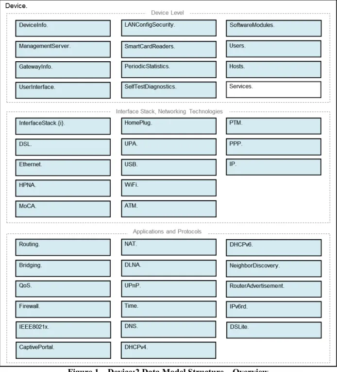
The cornerstone of the Device:2 data model is the interface stacking mechanism. Network interfaces and protocol layers are modeled as independent data objects (a.k.a. interface objects) that can be stacked, one on top of the other, into whatever configuration a device might support. Figure 1 illustrates the top-level Device:2 data model structure. Figure 2, Figure 3, and Figure 4 illustrate the data model structure in greater detail. See Section 5 for the complete list of objects.
• Interface objects are indicated by a “dashed” background pattern.
• Objects that reference interface objects are indicated by a “dotted” background pattern.
2
References and Terminology
2.1 ConventionsIn this Technical Report, several words are used to signify the requirements of the specification. These words are always capitalized. More information can be found be in RFC 2119 [1].
MUST This word, or the term “REQUIRED”, means that the definition is an absolute requirement of the specification.
MUST NOT This phrase means that the definition is an absolute prohibition of the specification.
SHOULD This word, or the adjective “RECOMMENDED”, means that there could exist valid reasons in particular circumstances to ignore this item, but the full implications need to be understood and carefully weighed before choosing a different course.
SHOULD NOT This phrase, or the phrase “NOT RECOMMENDED” means that there could exist valid reasons in particular circumstances when the particular behavior is acceptable or even useful, but the full implications need to be understood and the case carefully weighed before implementing any behavior described with this label.
MAY This word, or the adjective “OPTIONAL”, means that this item is one of an allowed set of alternatives. An implementation that does not include this option MUST be prepared to inter-operate with another implementation that does include the option.
The key words “DEPRECATED” and “OBSOLETED” in this Technical Report are to be interpreted as defined in TR-106 [3].
2.2 References
The following references are of relevance to this Technical Report. At the time of publication, the editions indicated were valid. All references are subject to revision; users of this Technical Report are therefore encouraged to investigate the possibility of applying the most recent edition of the references listed below.
A list of currently valid Broadband Forum Technical Reports is published at www.broadband-forum.org.
[1] RFC 2119, Key words for use in RFCs to Indicate Requirement Levels, IETF, 1997 [2] TR-069 Amendment 3, CPE WAN Management Protocol, Broadband Forum, 2010 [3] TR-106 Amendment 5, Data Model Template for TR-069-Enabled Devices, Broadband
Forum, 2010
[5] XML Schema Part 0: Primer Second Edition, W3C, 2004 [6] RFC 2863, The Interfaces Group MIB, IETF, 2000
[7] X.200, Information technology - Open Systems Interconnection - Basic Reference Model: The basic model, ITU-T, 1994
[8] 802.1D-2004, Media Access Control (MAC) Bridges, IEEE, 2004 [9] 802.1Q-2005, Virtual Bridged Local Area Networks, IEEE, 2006 [10] RFC 2597, Assured Forwarding PHB Group, IETF, 1999
[11] RFC 3246, An Expedited Forwarding PHB (Per-Hop Behavior), IETF, 2002 [12] RFC 3261, SIP: Session Initiation Protocol, IETF, 2002
[13] RFC 3435, Media Gateway Control Protocol (MGCP) - Version 1.0, IETF, 2003 [14] RFC 4566, SDP: Session Description Protocol, IETF, 2006
[15] RFC 2453, RIP Version 2, IETF, 1998
[16] RFC 2460, Internet Protocol Version 6 (IPv6) Specification, IETF, 1998 [17] RFC 2464, Transmission of IPv6 Packets over Ethernet Networks, IETF, 1998 [18] RFC 3315, Dynamic Host Configuration Protocol for IPv6 (DHCPv6), IETF, 2003 [19] RFC 3633, IPv6 Prefix Options for Dynamic Host Cofiguration Protocol (DHCP) version
6, IETF, 2003
[20] RFC 4191, Default Router Preferences and More-Specific Routes, IETF, 2005 [21] RFC 4193, Unique Local IPv6 Unicast Addresses, IETF, 2005
[22] RFC 4861, Neighbor Discovery for IP version 6 (IPv6), IETF, 2007 [23] RFC 4862, IPv6 Stateless Address Autoconfiguration, IETF, 2007 [24] RFC 5072, IP Version 6 over PPP, IETF, 2007
[25] RFC 5969, IPv6 Rapid Deployment on IPv4 Infrastructures (6rd) – Protocol Specification, IETF, 2010
[26] RFC 6106, IPv6 Router Advertisement Options for DNS Configuration, IETF, 2010 [27] draft-ietf-softwire-dual-stack-lite, Dual-Stack Lite Broadband Deployments Following
IPv4 Exhaustion, IETF, 2010
[28] draft-ietf-softwire-ds-lite-tunnel-option, Dynamic Host Configuration Protocol for IPv6 (DHCPv6) Options for Dual-Stack Lite, IETF, 2010
[29] TR-101, Migration to Ethernet Based DSL Aggregation, Broadband Forum, 2006 [30] TR-124 Issue 2, Functional Requirements for Broadband Residential Gateway Devices,
Broadband Forum, 2010
[31] TR-177, IPv6 in the context of TR-101, Broadband Forum, 2010 [32] TR-187, IPv6 for PPP Broadband Access, Broadband Forum, 2010
[33] ICSA Baseline Modular Firewall Certification Criteria, Baseline module – version 4.1, ICSA Labs, 2008
[34] ICSA Residential Modular Firewall Certification Criteria, Required Services Security Policy – Residential Category module – version 4.1, ICSA Labs, 2008
2.3 Definitions
The following terminology is used throughout this Technical Report.
ACS Auto-Configuration Server. This is a component in the broadband network responsible for auto-configuration of the CPE for advanced services.
CPE Customer Premises Equipment; refers to any TR-069-enabled [2] device and therefore covers Residential Gateways, LAN-side End Devices, and other Network Infrastructure Devices.
Component A named collection of Objects and/or Parameters and/or Profiles that can be included anywhere within a Data Model.
CWMP CPE WAN Management Protocol. Defined in TR-069 [2], CWMP is a communication protocol between an ACS and CPE that defines a mechanism for secure auto-configuration of a CPE and other CPE management functions in a common framework.
Data Model A hierarchical set of Objects and/or Parameters that define the managed objects accessible via TR-069 for a particular CPE.
Device Used here as a synonym for CPE.
DM Instance Data Model Schema instance document. This is an XML document that conforms to the DM Schema and to any additional rules specified in or referenced by the DM Schema.
DM Schema Data Model Schema. This is the XML Schema [5] that is used for defining data models for use with CWMP.
Downstream Interface
A physical interface object whose Upstream parameter is set to false, or an interface that is associated with such a physical interface via the InterfaceStack. For example, a downstream IP Interface is an IP.Interface object that is associated with an Upstream=false physical layer interface.
Interface Object A type of Object that models a network interface or protocol layer. Commonly referred to as an interface. They can be stacked, one on top of the other, using Path References in order to dynamically define the relationships between interfaces. Object A named collection of Parameters and/or other Objects.
Parameter A name-value pair representing a manageable CPE parameter made accessible to an
ACS for reading and/or writing.
Path Reference Describes how a parameter can reference another parameter or object via its path name (Section A.2.3.4/TR-106 [3]). Such a reference can be weak or strong (Section A.2.3.6/TR-106 [3]).
Upstream Interface
A physical interface object whose Upstream parameter is set to true, or an interface that is associated with such a physical interface via the InterfaceStack. For example, an upstream IP Interface is an IP.Interface object that is associated with an Upstream=true physical layer interface.
2.4 Abbreviations
This Technical Report uses the following abbreviations:
ATM Asynchronous Transfer Mode.
DHCP Dynamic Host Configuration Protocol
DSL Digital Subscriber Line.
IP Internet Protocol.
OSI Open Systems Interconnection.
PPP Point-to-Point Protocol.
PTM Packet Transfer Mode.
RG Residential Gateway
RPC Remote Procedure Call.
SSID Service Set Identifier.
URI Uniform Resource Identifier [4].
3
Technical Report Impact
3.1 Energy EfficiencyTR-181 Issue 2 Amendment 2 has no impact on Energy Efficiency.
3.2 IPv6
TR-181 Issue 2 Amendment 2 defines IPv6 extensions1 to the Device:2 data model.
3.3 Security
TR-181 Issue 2 Amendment 2 has no impact on Security.
4
Architecture
4.1 Interface LayersThis Technical Report models network interfaces and protocol layers as independent data objects, generally referred to as interface objects (or interfaces). Interface objects can be stacked, one on top of the other, using path references in order to dynamically define the relationships between interfaces.
The interface object and interface stack are concepts inspired by RFC 2863 [6].
Within the Device:2 data model, interface objects are arbitrarily restricted to definitions that operate at or below the IP network layer (i.e. layers 1 through 3 of the OSI model [7]). However, vendor-specific interface objects MAY be defined which fall outside this restricted scope.
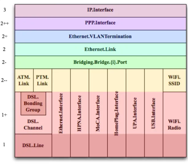
Figure 5 lists the interface objects defined in the Device:2 data model. The indicated OSI layer is non-normative; it serves as a guide only, illustrating at what level in the stack an interface object is expected to appear. However, a CPE need not support or use all interfaces, which means that the figure does not reflect all possible stacking combinations and restrictions. For example, one CPE stack might exclude DSL Bonding, while another CPE stack might include DSL Bonding but exclude Bridging, while still another might include VLANTermination under PPP, or VLANTermination under IP with no PPP, or even Ethernet Link under IP with no VLANTermination and no PPP.
NOTE – Throughout this Technical Report, object names are often abbreviated in order to improve readability. For example, Device.Ethernet.VLANTermination.{i}. is the full name of a Device:2 object, but might casually be referred to as Ethernet.VLANTermination.{i} or VLANTermination.{i} or
VLANTermination, just so long as the abbreviation is unambiguous (with respect to similarly named objects defined elsewhere within the data model).
Figure 5 – OSI Layers and Interface Objects23 4.2 Interface objects
An interface object is a type of network interface or protocol layer. Each type of interface is modeled by a Device:2 data model table, with a row per interface instance (e.g. IP.Interface.{i} for IP Interfaces).
Each interface object contains a core set of parameters and objects, which serves as the template for defining interface objects within the data model. Interface objects can also contain other parameters and sub-objects specific to the type of interface.
2 Note that, because new minor versions of the Device:2 data model can be defined without re-publishing this
Technical Report, the figure is not necessarily up-to-date.
3 The Bridge.{i}.Port.{i} object models both management (upwards facing) Bridge Ports and non-management
(downwards facing) Bridge Ports, where each instance is configured as one or the other. Management Bridge Ports are stacked above non-management Bridge Ports.
The core set of parameters consists of:
• Enable The administrative state of the interface (i.e. boolean indicating enabled
or disabled)
• Status The operational state of the interface (i.e. Up, Down, Unknown,
Dormant, NotPresent, LowerLayerDown, Error)
• Alias An alternate name used to identify the interface, which is assigned an
initial value by the CPE but can later be chosen by the ACS
• Name The textual name used to identify the interface, which is chosen by the
CPE
• LastChange The accumulated time in seconds since the interface entered its current
operational state
• LowerLayers A list of path references to interface objects that are stacked
immediately below the interface
Also, a core set of statistics parameters is contained within a Stats sub-object. The definition of these parameters MAY be customized for each interface type. The core set of parameters within the Stats sub-object consists of:
• BytesSent The total number of bytes transmitted out of the interface,
including framing characters.
• BytesReceived The total number of bytes received on the interface,
including framing characters.
• PacketsSent The total number of packets transmitted out of the
interface.
• PacketsReceived The total number of packets received on the interface. • ErrorsSent The total number of outbound packets that could not be
transmitted because of errors.
• ErrorsReceived The total number of inbound packets that contained errors
preventing them from being delivered to a higher-layer protocol.
• UnicastPacketsSent The total number of packets requested for transmission
which were not addressed to a multicast or broadcast address at this layer, including those that were discarded or not sent.
• UnicastPacketsReceived The total number of received packets, delivered by this
layer to a higher layer, which were not addressed to a multicast or broadcast address at this layer.
• DiscardPacketsSent The total number of outbound packets which were chosen
to be discarded even though no errors had been detected to prevent their being transmitted.
• DiscardPacketsReceived The total number of inbound packets which were chosen
to be discarded even though no errors had been detected to prevent their being delivered.
• MulticastPacketsSent The total number of packets that higher-layer protocols
requested for transmission and which were addressed to a multicast address at this layer, including those that were discarded or not sent.
• MulticastPacketsReceived The total number of received packets, delivered by this
layer to a higher layer, which were addressed to a multicast address at this layer.
• BroadcastPacketsSent The total number of packets that higher-level protocols
requested for transmission and which were addressed to a broadcast address at this layer, including those that were discarded or not sent.
• BroadcastPacketsReceived The total number of received packets, delivered by this
layer to a higher layer, which were addressed to a broadcast address at this layer.
•
UnknownProtoPackets-Received
The total number of packets received via the interface, which were discarded because of an unknown or unsupported protocol.
NOTE – The CPE MUST reset an interface's Stats parameters (unless otherwise stated in individual object or parameter descriptions) either when the interface becomes operationally down due to a previous administrative down (i.e. the interface's Status parameter transitions to a down state after the interface is disabled) or when the interface becomes administratively up (i.e. the interface's Enable parameter transitions from false to true). Administrative and operational status is discussed in Section 4.2.2.
4.2.1 Lower Layers
Each interface object can be stacked on top of zero or more other interface objects, which MUST be specified using its LowerLayers parameter. By having each interface object, in turn, reference the interface objects in its lower layer, a logical hierarchy of all interface relationships is built up. The LowerLayers parameter is a comma-separated list of path references to interface objects. Each item in the list represents an interface object that is stacked immediately below the referencing interface. If a referenced interface is deleted, the CPE MUST remove the corresponding item from this list (i.e. items in the LowerLayers parameter are strong references). These relationships between interface objects can either be set by management action, in order to specify new interface configurations, or be pre-configured within the CPE.
A CPE MUST reject any attempt to set LowerLayers values that would result in an invalid or unsupported configuration. The corresponding fault response from the CPE MUST indicate this using an Invalid Parameter Value fault code (9007). See Section A.3.2.1/TR-069 [2] for further details on SetParameterValues fault responses.
The lowest layer in a fully configured and operational stack is generally the physical interface (e.g. DSL Line instance representing a DSL physical link). Within these physical interface objects the LowerLayers parameter will be an empty list, unless some lower layer vendor-specific interface objects are defined and present. Higher layer interface objects MAY operate without a physical layer being modeled, however this is a local matter to the CPE.
Figure 6 illustrates the use of the LowerLayers parameter. A, B, C, and D represent interface objects. Interface A’s LowerLayers parameter references interfaces B and C. Interface B’s LowerLayers parameter references interface D. Interfaces C and D have no interface references specified in their LowerLayers parameters. In this way, a multi-layered interface stack is configured. If the ACS were to delete interface B, then the CPE would update interface A’s LowerLayers parameter to no longer reference interface B (and interface D would be stranded, no longer referenced by the now deleted interface B).
Figure 6 – Interface LowerLayers
4.2.2 Administrative and Operational Status
NOTE – Many of the requirements outlined in this section were derived from Section 3.1.13/RFC 2863 [6].
An interface object’s Enable and Status parameters specify the current administrative and operational status of the interface, respectively. Valid values for the Status parameter are: Up, Down, Unknown, Dormant, NotPresent, LowerLayerDown, and Error.
The CPE MUST do everything possible in order to follow the operational state transitions as described below. In some cases these requirements are defined as SHOULD; this is not an indication that they are optional. These transitions, and the relationship between the Enable parameter and the Status parameter, are required behavior – it is simply the timing of how long these state transitions take that is implementation specific.
When the Enable parameter is false the Status parameter SHOULD normally be Down (or NotPresent or Error if there is a fault condition on the interface). Note that when the Enable parameter transitions to false, it is possible that the Status parameter’s transition to Down might occur after a small time lag if the CPE needs to first complete certain operations (e.g. finish transmitting a packet).
D
A
When the Enable parameter is changed to true, the Status SHOULD do one of the following:
• Change to Up if and only if the interface is able to transmit and receive network traffic. • Change to Dormant if and only if the interface is operable, but is waiting for external
actions before it can transmit and receive network traffic.
• Change to LowerLayerDown if and only if the interface is prevented from entering the
Up state because one or more of the interfaces beneath it is down.
• Remain in the Error state if there is an error or other fault condition detected on the
interface.
• Remain in the NotPresent state if the interface has missing (typically hardware)
components.
• Change to Unknown if the state of the interface can not be determined for some reason.
The Dormant state indicates that the interface is operable, but it is waiting for external events to occur before it can transmit/receive traffic. When such events occur, and the interface is then able to transmit/receive traffic, the Status SHOULD change to the Up state. Note that both the Up and Dormant states are considered healthy states.
The Down, NotPresent, LowerLayerDown, and Error states all indicate that the interface is down. The NotPresent state indicates that the interface is down specifically because of a missing (typically hardware) component. The LowerLayerDown state indicates that the interface is stacked on top of one or more other interfaces, and that this interface is down specifically because one or more of these lower-layer interfaces is down.
The Error state indicates that the interface is down because an error or other fault condition was detected on the interface.
4.2.3 Stacking and Operational Status
NOTE – The requirements outlined in this section were derived from Section 3.1.14/RFC 2863 [6].
When an interface object is stacked on top of lower-layer interfaces (i.e. is not a bottommost layer in the stack), then:
• The interface SHOULD be Up if it is able to transmit/receive traffic due to one or more
interfaces lower down in the stack being Up, irrespective of whether other interfaces below it are in a non-Up state (i.e. the interface is functioning in conjunction with at least some of its lower-layered interfaces).
• The interface MAY be Up or Dormant if one or more interfaces lower down in the stack
are Dormant and all other interfaces below it are in a non-Up state.
• The interface is expected to be LowerLayerDown while all interfaces lower down in the
stack are either Down, NotPresent, LowerLayerDown, or Error.
4.2.4 Vendor-specific Interface Objects
Vendor-specific interface objects MAY be defined and used. If such objects are specified by vendors, they MUST be preceded by X_<VENDOR>_ and follow the syntax for vendor extensions used for parameter names (as defined in Section 3.3/TR-106 [3]).
If the ACS encounters an unknown vendor-specific interface object within a CPE’s interface stack, rather than responding with a fault, the ACS MUST proceed as if this object’s upper-layer interfaces were directly linked to its lower-layer interfaces. This applies whether the ACS encounters such an object via the InterfaceStack table (Section 4.3) or via an interface object’s LowerLayers parameter.
Figure 7 illustrates a stacked vendor-specific interface object being bypassed by the ACS, where there is just one object below the vendor-specific object.
IP.Interface.1 Ethernet.Link.1 X_00256D_AB. Interface.1 IP.Interface.1 Ethernet.Link.1 IP.Interface.1 Ethernet.Link.1 X_00256D_AB. Interface.1 IP.Interface.1 Ethernet.Link.1
Figure 7 – Ignoring a Vendor-specific Interface Object in the Stack
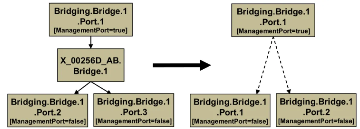
Figure 8 illustrates a stacked vendor-specific interface object being bypassed by the ACS, where there are multiple objects below the vendor-specific object.
Bridging.Bridge.1 .Port.1 [ManagementPort=true] Bridging.Bridge.1 .Port.2 [ManagementPort=false] X_00256D_AB. Bridge.1 Bridging.Bridge.1 .Port.3 [ManagementPort=false] Bridging.Bridge.1 .Port.1 [ManagementPort=false] Bridging.Bridge.1 .Port.2 [ManagementPort=false] Bridging.Bridge.1 .Port.1 [ManagementPort=true] Bridging.Bridge.1 .Port.1 [ManagementPort=true] Bridging.Bridge.1 .Port.2 [ManagementPort=false] X_00256D_AB. Bridge.1 Bridging.Bridge.1 .Port.3 [ManagementPort=false] Bridging.Bridge.1 .Port.1 [ManagementPort=false] Bridging.Bridge.1 .Port.2 [ManagementPort=false] Bridging.Bridge.1 .Port.1 [ManagementPort=true]
Figure 8 – Ignoring a Vendor-specific Interface Object in the Stack (multiple sub-objects) 4.3 InterfaceStack Table
Although the interface stack can be traversed via LowerLayers parameters (as described in Section 4.2.1 Lower Layers), an alternate mechanism is provided to aid in visualizing the overall stacking relationships and to quickly access objects within the stack.
The InterfaceStack table is a Device:2 data model object, namely Device.InterfaceStack.{i}. This is a read-only table whose rows are auto-generated by the CPE based on the current relationships that are configured between interface objects (via each interface instance’s LowerLayers parameter). Each table row represents a “link” between a higher-layer interface object
(referenced by its HigherLayer parameter) and a lower-layer interface object (referenced by its LowerLayer parameter). This means that an InterfaceStack table row’s HigherLayer and LowerLayer parameters will always both be non-null.
NOTE – As a consequence, interface instances that have been stranded will not be represented within the InterfaceStack table4. It is also likely that multiple, disjoint groups of stacked interface objects will coexist within the table (for example, each IP interface will be the root of a disjoint group; unused “fragments”, e.g. a secondary DSL channel with a configured ATM PVC that isn’t attached to anything above, will linger if they remain interconnected; and finally, partially configured “fragments” can be present when an interface stack is being set up).
A CPE MUST autonomously add or remove rows in the InterfaceStack table in response to the following circumstances:
• An interface’s LowerLayers parameter was updated to remove a reference to another
interface (i.e. a “link” is being removed from the stack due to a SetParameterValues request).
• An interface’s LowerLayers parameter was updated to add a reference to another
interface (i.e. a “link” is being added to the stack due to a SetParameterValues request).
• An interface was deleted that had referenced, or been referenced by, one other interface
(i.e. a “link” is being removed from the stack due to a DeleteObject request).
• An interface was deleted that had referenced, or been referenced by, multiple interfaces
(i.e. multiple “links” are being removed from the stack due to a DeleteObject request). Once the CPE issues the SetParameterValuesResponse or the DeleteObjectResponse, all autonomous InterfaceStack table changes associated with the corresponding request (as described in the preceding paragraph) MUST be available for subsequent commands to operate on, regardless of whether or not these changes have been applied by the CPE (see TR-069 [2] Sections A.3.2.1 and A.3.2.7 for background on these RPC methods).
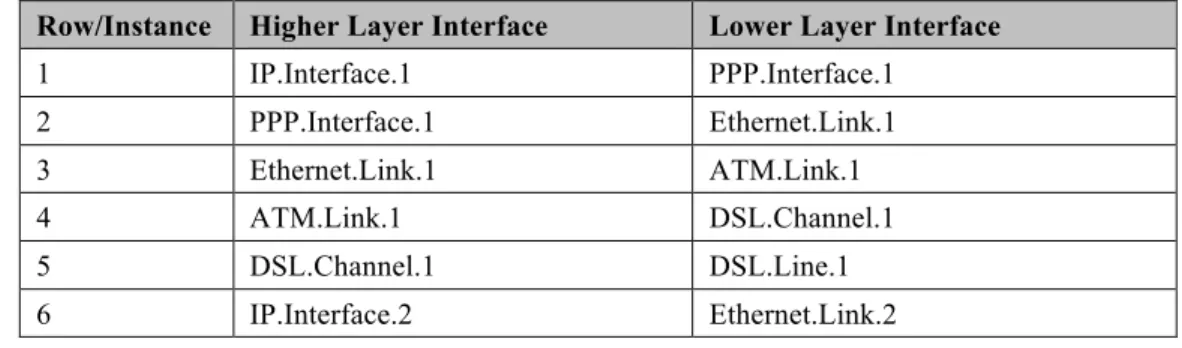
As an example, Table 1 lists an InterfaceStack table configuration imagined for a fictitious, simple router. Each row in this table corresponds to a row in the InterfaceStack table. The specified objects and instance numbers are manufactured for the sake of this example; real world configurations will likely differ.
Table 1 – Simple Router Example (InterfaceStack table)
Row/Instance Higher Layer Interface Lower Layer Interface
1 IP.Interface.1 PPP.Interface.1 2 PPP.Interface.1 Ethernet.Link.1 3 Ethernet.Link.1 ATM.Link.1 4 ATM.Link.1 DSL.Channel.1 5 DSL.Channel.1 DSL.Line.1 6 IP.Interface.2 Ethernet.Link.2
4 An interface instance is considered stranded when it has no lower layer references to or from other interface
instances. Stranded interface instances will be omitted from the InterfaceStack table until such time as they are stacked, above or below another interface instance, via a LowerLayers parameter reference.
Row/Instance Higher Layer Interface Lower Layer Interface 7 Ethernet.Link.2 ATM.Link.2 8 ATM.Link.2 DSL.Channel.1 9 IP.Interface.3 Ethernet.Link.3 10 Ethernet.Link.3 Bridging.Bridge.1.Port.1 11 Bridging.Bridge.1.Port.1 Bridging.Bridge.1.Port.2 12 Bridging.Bridge.1.Port.2 Ethernet.Interface.1 13 Bridging.Bridge.1.Port.1 Bridging.Bridge.1.Port.3 14 Bridging.Bridge.1.Port.3 Ethernet.Interface.2 15 Bridging.Bridge.1.Port.1 Bridging.Bridge.1.Port.4 16 Bridging.Bridge.1.Port.4 WiFi.SSID.1 17 WiFi.SSID.1 WiFi.Radio.1
By looking at the rows from the example InterfaceStack table as a whole, we can visualize the overall stack configuration. Figure 9 shows how this information can be pictured. Interface instances are represented by colored boxes, while InterfaceStack instances are represented by numbered circles. Bridging.Bridge.1 .Port.4 [ManagementPort=false] IP.Interface.2 IP.Interface.3 router WAN LAN L1 L2 L2+ L3 layer Ethernet.Link.2 WiFi.SSID.1 IP.Interface.1 Ethernet.Link.1 PPP.Interface.1 3 8 9 Ethernet.Link.3 6 7 11 xxx Interface Object InterfaceStack entry n Bridging.Bridge.1.Port.1 [ManagementPort=true] LAN LAN Bridging.Bridge.1 .Port.3 [ManagementPort=false] Bridging.Bridge.1 .Port.2 [ManagementPort=false] 15 1 13 2 4 17 12 14 16 10 WiFi.Radio.1 [Upstream=false] Ethernet.Interface.2 [Upstream=false] Ethernet.Interface.1 [Upstream=false] DSL.Line.1 [Upstream=true] ATM.Link.1 ATM.Link.2 DSL.Channel.1 5
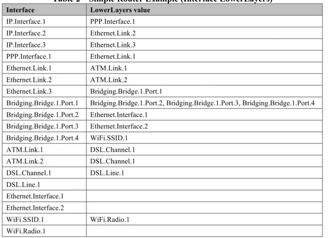
Finally, Table 2 completes the example by listing each interface instance and its corresponding LowerLayers parameter value.
Table 2 – Simple Router Example (Interface LowerLayers)
Interface LowerLayers value
IP.Interface.1 PPP.Interface.1 IP.Interface.2 Ethernet.Link.2 IP.Interface.3 Ethernet.Link.3 PPP.Interface.1 Ethernet.Link.1 Ethernet.Link.1 ATM.Link.1 Ethernet.Link.2 ATM.Link.2 Ethernet.Link.3 Bridging.Bridge.1.Port.1
Bridging.Bridge.1.Port.1 Bridging.Bridge.1.Port.2, Bridging.Bridge.1.Port.3, Bridging.Bridge.1.Port.4 Bridging.Bridge.1.Port.2 Ethernet.Interface.1 Bridging.Bridge.1.Port.3 Ethernet.Interface.2 Bridging.Bridge.1.Port.4 WiFi.SSID.1 ATM.Link.1 DSL.Channel.1 ATM.Link.2 DSL.Channel.1 DSL.Channel.1 DSL.Line.1 DSL.Line.1 Ethernet.Interface.1 Ethernet.Interface.2 WiFi.SSID.1 WiFi.Radio.1 WiFi.Radio.1
5
Parameter Definitions
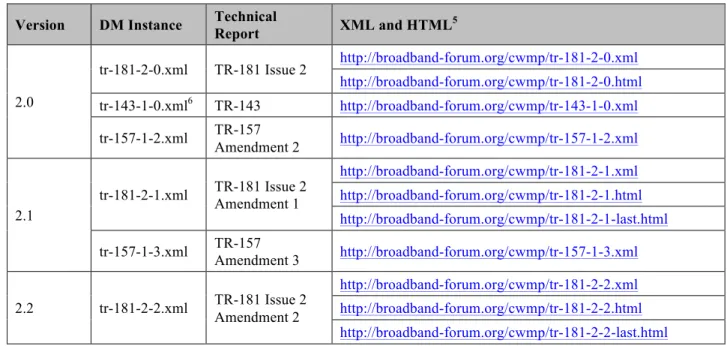
The normative definition of the Device:2 data model is split between several DM Instance documents (see TR-106 [3] Annex A). Table 3 lists the Device:2 data model versions and DM Instances that had been defined at the time of writing. It also indicates the corresponding Technical Reports and gives links to the associated XML and HTML files. For a given revision of the data model, the corresponding TR-181 Issue 2 XML document defines the Device:2 model itself and imports additional components from the other XML documents listed. Each TR-181 Issue 2 HTML document is a report generated from the XML files, and lists a consolidated view of the Device:2 data model in human-readable form.
Note that, because new minor versions of the Device:2 data model can be defined without re-publishing this Technical Report, the table is not necessarily up-to-date. An up-to-date version of this information can always be found at http://www.broadband-forum.org/cwmp.
Table 3 – Device:2 Data Model Versions
Version DM Instance Technical Report XML and HTML5
2.0 tr-181-2-0.xml TR-181 Issue 2 http://broadband-forum.org/cwmp/tr-181-2-0.xml http://broadband-forum.org/cwmp/tr-181-2-0.html tr-143-1-0.xml6 TR-143 http://broadband-forum.org/cwmp/tr-143-1-0.xml tr-157-1-2.xml TR-157 Amendment 2 http://broadband-forum.org/cwmp/tr-157-1-2.xml 2.1 tr-181-2-1.xml TR-181 Issue 2 Amendment 1 http://broadband-forum.org/cwmp/tr-181-2-1.xml http://broadband-forum.org/cwmp/tr-181-2-1.html http://broadband-forum.org/cwmp/tr-181-2-1-last.html tr-157-1-3.xml TR-157 Amendment 3 http://broadband-forum.org/cwmp/tr-157-1-3.xml 2.2 tr-181-2-2.xml TR-181 Issue 2 Amendment 2 http://broadband-forum.org/cwmp/tr-181-2-2.xml http://broadband-forum.org/cwmp/tr-181-2-2.html http://broadband-forum.org/cwmp/tr-181-2-2-last.html
5 The HTML with a name of the form tr-xxx-i-a.html, e.g. tr-181-2-1.html, lists the entire data model. The HTML
with a name of the form tr-xxx-i-a-last.html, e.g. tr-181-2-1-last.html, lists only the changes since the previous version.
6 The minimum valid version of the tr-143-1-0.xml document is corrigendum 2. Earlier versions are not supported
Annex A:
Bridging and Queuing
A.1
Queuing and Bridging Model
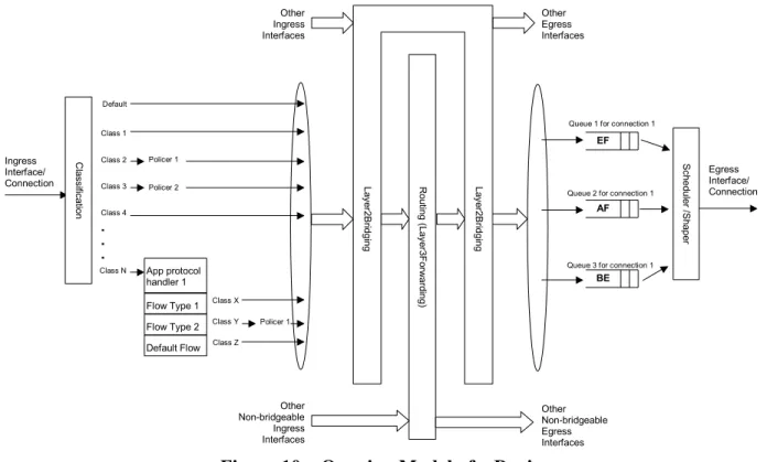
Figure 10 shows the queuing and bridging model for a device. This model relates to the QoS object as well as the Bridging and Routing objects. The elements of this model are described in the following sections.
NOTE – the queuing model described in this Annex is meant strictly as a model to clarify the intended behavior of the related data objects. There is no implication intended that an implementation has to be structured to conform to this model.
. . . Class 2 Class 3 Class 4 Class N EF AF Class 1
Queue 1 for connection 1
Queue 2 for connection 1 Policer 1
BE
Queue 3 for connection 1 Ingress Interface/ Connection Egress Interface/ Connection Policer 2 Class X Class Y Class Z Default C la ssi fica tio n App protocol handler 1 Flow Type 1 Flow Type 2 Default Flow Policer 1 Other Ingress Interfaces Other Non-bridgeable Egress Interfaces R ou tin g (L aye r3 F orw ard in g) Other Non-bridgeable Ingress Interfaces La ye r2 Bri dg in g La ye r2 Bri dg in g Other Egress Interfaces Sch ed ule r /Sh ap er
Figure 10 – Queuing Model of a Device
A.1.1 Packet Classification
The Classification table within the QoS object specifies the assignment of each packet arriving at an ingress interface to a specific internal class. This classification can be based on a number of matching criteria, such as destination and source IP address, destination and source port, and protocol.
Each entry in the Classification table includes a series of parameters, each indicated to be a Classification Criterion. Each classification criterion can be set to a specified value, or can be set to a value that indicates that criterion is not to be used. A packet is defined to match the classification criteria for that table entry only if the packet matches all of the specified criteria. That is, a logical AND operation is applied across all classification criteria within a given Classification table entry.
NOTE – to apply a logical OR to sets of classification criteria, multiple entries in the Classification table can be created that specify the same resulting queuing behavior.
For each classification criterion, the Classification table also includes a corresponding “exclude” flag. This flag can be used to invert the sense of the associated classification criterion. That is, if this flag is false for a given criterion, the classifier is to include only packets that meet the specified criterion (as well as all others). If this flag is true for a given criterion, the classifier is to include all packets except those that meet the associated criterion (in addition to meeting all other criteria).
For a given entry in the Classification table, the classification is to apply only to the interface specified by the Interface parameter. This parameter can specify a particular ingress interface or all sources. Depending on the particular interface, not all classification criteria will be applicable. For example, Ethernet layer classification criteria would not apply to packets arriving on a non-bridged ATM VC.
Packet classification is modeled to include all ingress packets regardless of whether they ultimately will be bridged or routed through the device.
A.1.1.1 Classification Order
The class assigned to a given packet corresponds to the first entry in the Classification table (given the specified order of the entries in the table) whose matching criteria match the packet. If there is no entry that matches the packet, the packet is assigned to a default class.
Classification rules are sensitive to the order in which they are applied because certain traffic might meet the criteria of more than one Classification table entry. The Order parameter is responsible for identifying the order in which the Classification entries are to be applied.
The following rules apply to the use and setting of the Order parameter:
Order goes in order from 1 to n, where n is equal to the number of entries in the
Classification table. 1 is the highest precedence, and n the lowest. For example, if entries with Order of 4 and 7 both have rules that match some particular traffic, the traffic will be classified according to the entry with the 4.
The CPE is responsible for ensuring that all Order values are unique and sequential.
o If an entry is added (number of entries becomes n+1), and the value specified for Order is greater than n+1, then the CPE will set Order to n+1.
o If an entry is added (number of entries becomes n+1), and the value specified for Order is less than n+1, then the CPE will create the entry with that specified value, and increment the Order value of all existing entries with Order equal to or greater than the specified value.
o If an entry is deleted, the CPE will decrement the Order value of all remaining entries with Order greater than the value of the deleted entry.
o If the Order value of an entry is changed, then the value will also be changed for other entries greater than or equal to the lower of the old and new values, and less than the
larger of the old and new values. If the new value is less than the old, then these other entries will all have Order incremented. If the new value is greater than the old, then the other entries will have Order decremented and the changed entry will be given a value of <new value>-1. For example, an entry is changed from 8 to 5. The existing 5 goes to 6, 6 to 7, and 7 to 8. If the entry goes from 5 to 8, then 6 goes to 5, 7 to 6, and the changed entry is 7. This is consistent with the behavior that would occur if the change were considered to be an Add of a new entry with the new value, followed by a Delete of the entry with the old value.
A.1.1.2 Dynamic Application Specific Classification
In some situations, traffic to be classified cannot be identified by a static set of classification criteria. Instead, identification of traffic flows might require explicit application awareness. The model accommodates such situations via the App and Flow tables in the QoS object.
Each entry in the App table is associated with an application-specific protocol handler, identified by the ProtocolIdentifier, which contains a URN. For a particular CPE, the AvailableAppList parameter indicates which protocol handlers that CPE is capable of supporting, if any. A list of standard protocol handlers and their associated URNs is specified in Section A.3, though a CPE can also support vendor-specific protocol handlers as well. Multiple App table entries can refer to the same ProtocolIdentifier.
The role of the protocol handler is to identify and classify flows based on application awareness. For example, a SIP protocol handler might identify a call-control flow, an audio flow, and a video flow. The App and Flow tables are used to specify the classification outcome associated with each such flow.
For each App table entry there can be one or more associated Flow table entries. Each flow table entry identifies a type of flow associated with the protocol handler. The Type parameter is used to identify the specific type of flow associated with each entry. For example, a Flow table entry for a SIP protocol handler might refer only to the audio flows associated with that protocol handler. A list of standard flow type values is given in Section A.3, though a CPE can also support vendor-specific flow types.
A protocol handler can be defined as being fed from the output of a Classification table entry. That is, a Classification entry can be used to single out control traffic to be passed to the protocol handler, which then subsequently identifies associated flows. Doing so allows more than one instance of a protocol handler associated with distinct traffic. For example, one could define two App table entries associated with SIP protocol handlers. If the classifier distinguished control traffic to feed into each handler based on the destination IP address of the SIP server, this could be used to separately classify traffic for different SIP service providers. In this case, each instance of the protocol handler would identify only those flows associated with a given service. Note that the Classification table entry that feeds each protocol handler wouldn’t encompass all of the flows; only the traffic needed by the protocol handler to determine the flows—typically only the control traffic.
A.1.1.3 Classification Outcome
Each Classification entry specifies a tuple composed of either:
• A TrafficClass and (optionally) a Policer, or • An App table entry
Each entry also specifies:
• Outgoing DiffServ and Ethernet priority marking behavior
• A ForwardingPolicy tag that can be referenced in the Routing table to affect packet
routing (note that the ForwardingPolicy tag affects only routed traffic)
Note that the information associated with the classification outcome is modeled as being carried along with each packet as it flows through the system.
If a packet does not match any Classification table entry, the DefaultTrafficClass, DefaultPolicer, default markings, and default ForwardingPolicy are used.
If a TrafficClass/Policer tuple is specified, classification is complete. If, however, an App is specified, the packet is passed to the protocol handler specified by the ProtocolIdentifier in the specified App table entry for additional classification (see Section A.1.1.2). If any of the identified flows match the Type specified in any Flow table entry corresponding to the given App table entry (this correspondence is indicated by the App identifier), the specified tuple and markings for that Flow table entry is used for packets in that flow. Other flows associated with the application, but not explicitly identified, use the default tuple and markings specified for that App table entry.
A.1.2 Policing
The Policer table defines the policing parameters for ingress packets identified by either a Classification table entry (or the default classification) or a dynamic flow identified by a protocol handler identified in the App table.
Each Policer table entry specifies the packet handling characteristics, including the rate requirements and behavior when these requirements are exceeded.
A.1.3 Queuing and Scheduling
The Queue table specifies the number and types of queues, queue parameters, shaping behavior, and scheduling algorithm to use. Each Queue table entry specifies the TrafficClasses with which it is associated, and a set of egress interfaces for which a queue with the corresponding characteristics needs to exist.
NOTE – If the CPE can determine that among the interfaces specified for a queue to exist, packets classified into that queue cannot egress to a subset of those interfaces (from knowledge of the current routing and bridging configuration), the CPE can choose not to instantiate the queue on those interfaces.
NOTE – Packets classified into a queue that exit through an interface for which the queue is not specified to exist, will instead use the default queuing behavior. The default queue itself will exist on all egress interfaces.
The model defined here is not intended to restrict where the queuing is implemented in an actual implementation. In particular, it is up to the particular implementation to determine at what protocol layer it is most appropriate to implement the queuing behavior (IP layer, Ethernet MAC layer, ATM layer, etc.). In some cases, however, the QoS configuration would restrict the choice of layer where queueing can be implemented. For example, if a queue is specified to carry traffic that is bridged, then it could not be implemented as an IP-layer queue.
NOTE – care needs to be taken to avoid having multiple priority queues multiplexed onto a single connection that is rate shaped. In such cases, the possibility exists that high priority traffic can be held back due to rate limits of the overall connection exceeded by lower priority traffic. Where possible, each priority queue will be shaped independently using the shaping parameters in the Queue and Shaping table.
The scheduling parameters defined in the Queue table apply to the first level of what might be a more general scheduling hierarchy. This specification does not specify the rules that an implementation needs to apply to determine the most appropriate scheduling hierarchy given the scheduling parameters defined in the Queue table.
As an example, take a situation where the output of four distinct queues is to be multiplexed into a single connection, and two entries share one set of scheduling parameters while the other two entries share a different set of scheduling parameters. In this case, it might be appropriate to implement this as a scheduling hierarchy with the first two queues multiplexed with a scheduler defined by the first pair, and the second two queues being multiplexed with a scheduler defined by the second pair. The lower layers of this scheduling hierarchy cannot be directly determined from the content of the Queue table.
A.1.4 Bridging
NOTE – from the point of view of a bridge, packets arriving into the bridge from the local router (either upstream or downstream) are treated as ingress packets, even though the same packets, which just left the router, are treated as egress from the point of view of the router. For example, a Filter table entry might admit packets on ingress to the bridge from a particular IP interface, which means that it admits packets on their way out of the router over this layer 3 connection.
For each interface, the output of the classifier is modeled to feed a set of 802.1D [8] or 802.1Q [9] layer 2 bridges as specified by the Bridging object. Each bridge specifies layer 2 connectivity between one or more layer 2 downstream and/or upstream interfaces, and optionally one or more layer 3 connections to the local router.
Each bridge corresponds to a single entry in the Bridge table of the Bridging object. The Bridge table contains the following sub-tables:
• Port table: models the Bridge ports, which are either management ports (modeling layer
3 connections to the local router) or non-management ports (modeling connections to layer 2 interfaces). Bridge ports are stackable interface objects (see Section 4.2).
• VLAN table: models the Bridge VLANs (relevant only to 802.1Q bridges). • VLANPort table: for each VLAN, defines the ports that comprise its member set
A.1.4.1 Filtering
Traffic from a given interface (or set of interfaces) can be selectively admitted to a given Bridge, rather than bridging all traffic from that interface. Each entry in the Filter table includes a series of classification criteria. Each classification criterion can be set to a specified value, or can be set to a value that indicates that criterion is not to be used. A packet is admitted to the Bridge only if the packet matches all of the specified criteria. That is, a logical AND operation is applied across all classification criteria within a given Filter table entry.
NOTE – to apply a logical OR to sets of classification criteria, multiple entries in the Filter table can be created that refer to the same interfaces and the same Bridge table entry.
NOTE – a consequence of the above rule is that, if a packet does not match the criteria of any of the enabled Filter table entries, then it will not be admitted to any bridges, i.e. it will be dropped. As a specific example of this, if none of the enabled Filter table entries reference a given interface, then all packets arriving on that interface will be dropped.
For each classification criterion, the Filter table also includes a corresponding “exclude” flag. This flag can be used to invert the sense of the associated classification criterion. That is, if this flag is false for a given criterion, the Bridge will admit only packets that meet the specified criterion (as well as all other criteria). If this flag is true for a given criterion, the Bridge will admit all packets except those that meet the associated criterion (in addition to meeting all other criteria).
Note that because the classification criteria are based on layer 2 packet information, if the selected port for a given Filter table entry is a layer 3 connection from the local router, the layer 2 classification criteria do not apply.
A.1.4.2 Filter Order
Any packet that matches the filter criteria of one or more filters is admitted to the Bridge associated with the first entry in the Filter table (relative to the specified Order).
The following rules apply to the use and setting of the Order parameter:
The Order goes in order from 1 to n, where n is equal to the number of filters. 1 is the highest precedence, and n the lowest.
The CPE is responsible for ensuring that all Order values among filters are unique and sequential.
o If a filter is added (number of filters becomes n+1), and the value specified for Order is greater than n+1, then the CPE will set Order to n+1.
o If a filter is added (number of entries becomes n+1, and the value specified for Order is less than n+1, then the CPE will create the entry with that specified value, and increment the Order value of all existing filters with Order equal to or greater than the specified value.
o If a filter is deleted, the CPE will decrement the Order value of all remaining filters with Order greater than the value of the deleted entry.
o If the Order value of a filter is changed, then the value will also be changed for other filters greater than or equal to the lower of the old and new values, and less than the larger of the old and new values. If the new value is less than the old, then these other entries will all have Order incremented. If the new value is greater than the old, then the other entries will have Order decremented and the changed entry will be given a value of <new value>-1. For example, an entry is changed from 8 to 5. The existing 5 goes to 6, 6 to 7, and 7 to 8. If the entry goes from 5 to 8, then 6 goes to 5, 7 to 6, and the changed entry is 7. This is consistent with the behavior that would occur if the change were considered to be an Add of a new filter with the new value, followed by a Delete of the filter with the old value.
A.2
Default Layer 2/3 QoS Mapping
Table 4 presents a “default” mapping between layer 2 and layer 3 QoS. In practice, it is a guideline for automatic marking of DSCP (layer 3) based upon Ethernet Priority (layer 2) and the other way around. Please refer to the QoS Classification table’s DSCPMark and EthernetPriorityMark parameters (and related parameters) for configuration of a default automatic DSCP / Ethernet Priority mapping.
Automatic marking of DSCP or Ethernet Priority is likely only in the following cases:
• WAN à LAN: to map DSCP (layer 3) to Ethernet Priority (layer 2) • LAN à WAN: to map Ethernet Priority (layer 2) to DSCP (layer 3)
Automatic marking in the LAN à LAN case is unlikely, since LAN QoS is likely to be supported only at layer 2, and LAN DSCP values, if used, will probably be a direct representation of Ethernet Priority, e.g. Ethernet Priority shifted left by three bits.
In the table, grayed and bolded items are added to allow two-way mapping between layer 2 and layer 3 QoS (where the mapping is ambiguous, the grayed values SHOULD be ignored and the bolded values SHOULD be used). If, when mapping from layer 3 to layer 2 QoS, the DSCP value is not present in the table, the mapping SHOULD be based only on the first three bits of the DSCP value, i.e. on DSCP & 111000.
Table 4 – Default Layer 2/3 QoS Mapping
Layer 2 Layer 3
Ethernet Priority Designation DSCP Per Hop Behavior
001 (1) BK 000000 (0x00) Default 010 (2) spare 000000 (0x00) 000 (0) BE 000000 (0x00) 000000 (0x00) Default CS0 011 (3) EE 001110 (0x0e) 001100 (0x0c) 001010 (0x0a) 001000 (0x08) AF13 AF12 AF11 CS1 100 (4) CL 010110 (0x16) 010100 (0x14) 010010 (0x12) 010000 (0x10) AF23 AF22 AF21 CS2
101 (5) VI 011110 (0x1e) 011100 (0x1c) 011010 (0x1a) 011000 (0x18) AF33 AF32 AF31 CS3 110 (6) VO 100110 (0x26) 100100 (0x24) 100010 (0x22) 100000 (0x20) AF43 AF42 AF41 CS4 110 (6) VO 101110 (0x2e) 101000 (0x28) EF CS5 111 (7) NC 110000 (0x30) 111000 (0x38) CS6 CS7
A.3
URN Definitions for App and Flow Tables
A.3.1 App ProtocolIdentifier
Table 5 lists the URNs defined for the QoS App table’s ProtocolIdentifier parameter. Additional standard or vendor-specific URNs can be defined following the standard syntax for forming URNs.
Table 5 – ProtocolIdentifer URNs
URN Description
urn:dslforum-org:sip Session Initiation Protocol (SIP) as defined by RFC 3261 [12] urn:dslforum-org:h.323 ITU-T Recommendation H.323
urn:dslforum-org:h.248 ITU-T Recommendation H.248 (MEGACO)
urn:dslforum-org:mgcp Media Gateway Control Protocol (MGCP) as defined by RFC 3435 [13] urn:dslforum-org:pppoe Bridged sessions of PPPoE
A.3.2 Flow Type
A syntax for forming URNs for the QoS Flow table’s Type parameter is defined for the Session Description Protocol (SDP) as defined by RFC 4566 [14]. Additional standard or vendor-specific URNs can be defined following the standard syntax for forming URNs.
A URN to specify an SDP flow is formed as follows:
urn:dslforum-org:sdp-[MediaType]-[Transport]
[MediaType] corresponds to the “media” sub-field of the “m” field of an SDP session description. [Transport] corresponds to the “transport” sub-field of the “m” field of an SDP session description. Non-alphanumeric characters in either field are removed (e.g., “rtp/avp” becomes “rtpavp”).
For example, the following would be valid URNs referring to SDP flows:
urn:dslforum-org:sdp-audio-rtpavp urn:dslforum-org:sdp-video-rtpavp urn:dslforum-org:sdp-data-udp
For flow type URNs following this convention, there is no defined use for TypeParameters, which SHOULD be left empty.
For the ProtocolIdentifier urn:dslforum-org:pppoe, a single flow type is defined referring to the entire PPPoE session. The URL for this flow type is:
urn:dslforum-org:pppoe
A.3.3 Flow TypeParameters
For the flow type urn:dslforum-org:pppoe, Table 6 specifies the defined TypeParameter values.
Table 6 – Flow TypeParameters values for flow type urn:dslforum-org:pppoe
Name Description of Value
ServiceName The PPPoE service name.
If specified, only bridged PPPoE sessions designated for the named service would be considered part of this flow.