SAE Paper 980199
Advanced Design and Validation Techniques
for Electronic Control Units
Max Fuchs, Michael Eckrich
BMW AG, Systems Engineering, EG-K-3, D-80788 München
Olaf Müller, Jan Philipps, Peter Scholz
Technical University Munich, Computer Science Department, D-80290 München
Copyright © 1998 Society of Automotive Engineers, Inc.
A B S T R A C T
Increasing demand for dynamically controlled safety features, passenger comfort, and operational convenience in upper class automobiles requires an intensive use of electronic control units including software portions. Modeling, simulation, rapid prototyping, and verification of the software need new technologies to guarantee passenger security and to accelerate the time-to-market of new products.
This paper presents the state-of-the-art of the design methods for the development of electronic control unit software at BMW. These design methods cover both discrete and continuous system parts, smoothly integrating the respective methods not merely on the code level, but on the documentation, simulation, and design level. In addition, we demonstrate two modeling and prototyping tools for discrete and continuous systems, namely Statemate and MatrixX, and discuss their advantages and drawbacks with respect to necessary prototyping demands.
Furthermore, we discuss how even more advanced technologies could be applied in the near future in the area of formal verification, aiming at the validation of safety-critical properties. Both design methods and verification have been applied to the case study of a cruise control system.
INTRODUCTION
The number of electronic control units (ECUs) in the automotive sector increases continuously. ECUs are used to guarantee an optimum of active passenger security, driving comfort, and operational convenience. Behind these units is the more and more complex software which controls all functions of an automobile – from the central locking system to the air condition and to the engine timing. This software has to perform according to the customers' wishes and requirements and has to be completely and faultlessly finished at latest with the start of the serial production. Beta-tests which are well-known from the software industry in the area of electronic data processing can not be used in this context: customers in daily road traffic cannot serve
as test persons, as it would contradict passenger security. Therefore, it is especially important to validate and verify all concepts and requirements as early as possible in the development process in order to meet the customers' requirements and yield maximum functional quality.
This paper presents new semiformal description techniques for the development of control software including a process model that describes the appropriate use of the techniques in every development phase. Emphasis is laid on simulation, rapid prototyping, and verification in early development phases. This allows an early validation of concepts, a better understanding and maintainability of the specification, and hence a considerable reduction of the overall development costs. The techniques describe the software no longer as an ASCII text by a huge amount of program listings, but by graphical and figurative presentations. Here, it has to be distinguished between discrete and continuous system parts.
The discrete parts describe states that can be recognized by immediate inspection, for example "Car is driving" or "Car is parking". They are represented in our approach by a special extended version of finite state machines, namely Statecharts [8]. Statecharts are supported by the commercially available development tool Statemate [11].
The continuous parts describe continuously ongoing processes, as they appear frequently for example in the motor management. The mathematical basis of these descriptions is laid by mathematical equation systems, which are the foundation of the development tool MatrixX [9]. With respect to the growing importance of product liability techniques related to model checking are currently investigated, which are used to formally verify essential system properties. These techniques base on mathematical algorithms and provide means to check system properties for all possible system states. This goes far beyond the capabilities of simulation, which is restricted to user-selected or randomized state trajectories.
The paper is organized as follows. Section 2 describes the development process for electronic control units tailored for a hybrid discrete/continuous specification. In Section 3 essential steps of this process are illustrated by a concrete case study, the development of a cruise control system. Finally, Section 4 introduces the even more advanced techniques of model checking, analyzes the state of the art of these techniques, and concludes.
A DESIGN PROCESS FOR ELECTRONIC CONTROL UNIT SOFTWARE
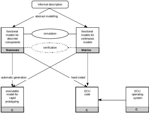
Presently, more than 50 electronic control units are integrated in an upper class BMW. Approximately, more than 40 percent of these units are hybrid systems, which consist of discrete as well as continuous parts. The design of such systems requires an elaborated design process. Our suggestion is pictured in Figure 1 and explained in the sequel.
• Starting with the informal problem description, for instance in form of a requirements specification or the developer´s ideas, we model the discrete software portions of the system in Statemate and the continuous portions in MatrixX.
• To verify and analyze the models, the single components of the system under development are simulated in the above mentioned tools. After that, the system is simulated as a whole by the aid of a special integration of these two tools on the simulation level.
• In order to validate the key concepts of the final product, we test an automatic-generated prototype already in the early design phases with a rapid prototyping hardware in the trunk of the automobile. This makes the system under development tangible.
• After having ensured the key concepts of the system by the aid of simulation and prototyping, we program the system under development in the specific code of the electronic control unit. Nowadays, this is still done by hand because available code generators are not yet capable to generate lean and optimized code that fits on small and cheap processors. Dealing with large-quantity products, it is cheaper to program the control units by hand for optimized code than to use more expensive units. The model code then has to be extended by operating system code.
To model discrete, state-based systems by the aid of Statemate, we follow principles of structured analysis [5]. We decompose a system functionally in sub-functions. These subfunctions are called activities or Activitycharts in Statemate. The interaction of them is expressed in terms of data and control flow. Like Statecharts [8], Activitycharts can be decomposed hierarchically. This helps us to structure our models. The behavior of each Activitychart is formulated by Statecharts. Statecharts are due to David Harel et al. and are an extended version of Mealy machines. In addition to hierarchy, Statecharts offer the possibility to combine automata in parallel that communicate via broadcast communication. informal description Statemate functional models for descrete components C executable model for rapid prototyping Matrixx functional models for continuous models C ECU code simulation verification hand coded C ECU operating system automatic generation abstract modelling
Before we start to simulate a model, we run some tests on the syntactical as well as on the semantic level to fix first design flaws. This is supported by the tool, too. Furthermore, as already mentioned, it is possible to carry out so-called dynamic tests and simulation. Finally, the prototype is generated and loaded on the prototype hardware.
For the specification of continuous systems we use the tool MatrixX. MatrixX is a compound tool that consists of a number of tools that can be used for the overall design process. The most important components are: a mathematical kernel, a graphical modeling and simulation tool, and a compiler for automatic code generation. Control systems are graphically designed and simulated with the so-called System Builder. A large design library supports the design process with various elements like trigonometric functions, interpolation blocks, and – more general – algebraic expressions.
Rapid prototyping is a mean to develop touch-and-feel-systems. This is an essential point for system development, especially in automobile industry. Already in the early design phases the product can be evaluated and discussed; not only by design specialists but also by members of the board of directors. Thus, it is on the one hand easier to develop a system that is in some sense optimal for the user. On the other hand, the time-to-market can be decreased. That is an important factor to remain competitive in a fast-paced market.
Rapid prototyping makes systems touchable without thinking about resource restrictions: in this product phase we do not have to care about critical resources like processor performance, memory allocation,
number and type of interfaces, and power
consumption, for instance. The designer can totally concentrate on the functionality of the system because a powerful prototyping environment is at our disposal. To be applicable for automobiles, a rapid prototyping hardware platform has to have a very flexible interface to the car electronics. Therefore, such an interface must offer the possibility to be configured freely and, in addition, must enable real time restrictions under two milliseconds. At BMW, we use a VME bus system combined with a Motorola CPU card together with the real time operating system VxWorks as target platform. When we transform the model in the target code into the programming language C that runs on the electronic control unit, we use optimized C libraries. This code is integrated on the control unit with the appropriate operating system hardware as well as the necessary software for communication on the field bus.
EXAMPLE APPLICATION: CRUISE CONTROL
The automatic cruise control for automobiles is a real-time system that contains both discrete and continuous elements. Hence, it is particularly well-suited as an application for the above-mentioned methods and techniques for the design of embedded systems. In this section, we first give a short description of the cruise control and then explain the design
process for embedded systems with these
techniques.
CRUISE CONTROL
The requirements specification [2] describes the operation of the cruise control as follows:
The cruise control maintains constant speed for
I
II
III
IV
V
VI
VII
acceleration
time
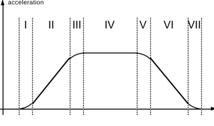
velocities of more than 40 km/h. Additional functions provide comfortable speed increase and decrease, and enable the car to automatically reach a preset speed. As shown in Figure 2, the temporal course of the acceleration when reaching a preset speed can be divided into seven phases. The driver can operate the cruise control with an input device that only allows the use of one function at a time. When the driver uses the brake or accelerator pedal, the automatic cruise control is immediately switched off.
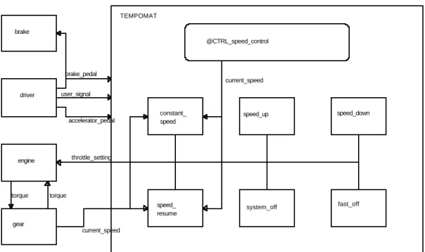
Figure 3 shows the functional decomposition of the cruise control, modeled as an Activitychart of Statemate. The interface of the cruise control to the vehicle’s other system components consists of the brake pedal, the accelerator pedal, the user signals from the input device, the current speed, and the throttle setting controlled by the cruise control. THE DISCRETE ELEMENTS OF THE MODEL
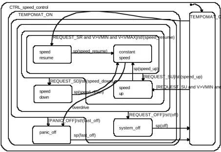
Which of the cruise control's functions is currently active is decided by the control activity @CTRL_speed_control in Figure 3. The priorities between the functions are specified by the state hierarchy in the control automaton shown in Figure 4: "fast_off" has the highest priority, "constant_speed" and "speed-resume" have the lowest priorities. A high-priority event is modeled by a transition at a high hierarchy layer. Hence, states with
lower priority are left implicitly.
By operating the input device, for example to resume speed, a signal (REQUEST_SR) is input from the device. In the model this activates the corresponding function by starting an activity in Figure 3 (by st!(speed_resume)). An activity can contain either another automaton (Statechart) for the specification of the activity's behavior, or it can contain control algorithms that were derived in MatrixX and analyzed for stability and their transient response.
THE CONTINUOUS ELEMENTS OF THE MODEL The function "speed_up" in Figure 3, for example, can be realized with a simple PD-T1 controller, if the controller's output characteristic models the acceleration process of phase III in Figure 2. Such controllers are specified in MatrixX as in Figure 5. The triangular symbols represent amplifiers in the signal flow, where the amplification factor is defined either by a parameter (for example %factor) or by a constant. The I/O behavior of the integrator and the delay function is defined by the z-transformed transfer function.
SIMULATION AND ANALYSIS
Executable specifications can be simulated and
TEMPOMAT @CTRL_speed_control constant_ speed speed_up system_off fast_off speed_down speed_ resume gear engine driver brake throttle_setting accelerator_pedal user_signal brake_pedal torque torque current_speed current_speed
analyzed. The formal proof of safety-critical properties, however, is not possible with simulation. This gap can be closed by model checking; in the next section we will elaborate on this verification technique.
Another step in the specification phase is rapid prototyping. Prototyping is an important device to obtain a proof-of-concept. For the technology and application of rapid prototyping, we refer to [10].
CONCLUSION AND FURTHER TECHNIQUES
In this article a new development process for electronic control units has been proposed. The process has already been field-tested and installed at BMW for major pilot studies. The major advantage of this innovative process is the enforced deployment of
semiformal development methodologies. These
methodologies provide great potentials to fulfill the following goals: development costs will be considerably diminished, quality will be increased, and the overall development time will be significantly
reduced. Nevertheless, it remains important to further improve this development process in future research. This is necessary as continuously new requirements on the development process of electronic control units arise.
One such requirement is automatic code generation of serial code in order to accelerate the development process further. The code generators that are state-of-the-art produce software code which is sufficient for the application in rapid prototyping as discussed in this paper, but is significantly too small and inefficient concerning the integration in the actual serial production.
Another important point in further research should be the study of formal verification techniques. In this area the techniques of model checking [3] are most promising. Model checking allows to verify safety-critical properties of the system in a fully automatic way. Therefore valuable insights may be gained concerning critical system states of the automobile. In the BMBF
CTRL_speed_control TEMPOMAT_ON speed resume speed down panic_off system_off constant speed speed up TEMPOMAT_OFF sp(speed_resume)
[REQUEST_SR and V>VMIN and V<VMAX]/st!(speed_resume)
[REQUEST_SD]/st!(speed_down) sp(speed_down) overdrive sp(fast_off) [PANIC_OFF]/st!(fast_off) [REQUEST_OFF]/st!(off) sp(off)
[REQUEST_SU and V>VMIN and V<VMAX]/st!(speed_up) [REQUEST_SU]/st!(speed_up)
sp(speed_up)
Figure 4: Statecharts specification of the priorities within the cruise control
project KorSys (Correct Systems) model checking techniques have been intensively studied, further improved, and an interface to the development process described in this paper has been produced. In the following, we summarize the foundations of model checking and the results we obtained by these techniques in the early phases of automotive software development.
Concerning model checking two different approaches have to be distinguished, namely discrete model checking [3] and hybrid model checking [1]. Whereas the former is restricted to discrete system descriptions, the latter allows the mixed specification of both discrete and continuous system properties. Nevertheless, both techniques follow the same principles: The system specification is described by some kind of finite state machine, the system property to be checked is described in a logic, that allows to express qualitative relations between system events. Using the techniques in [4] this logic can be completely hidden from the user by providing graphical timing diagrams. Concerning the system description, an important result could be obtained in the KorSys project with respect to discrete model checking: an interface to the commercial product Statemate has been produced, so that system specification can be performed in a graphical manner using all advantages of hierarchy, broadcasting, and parallelism provided by Statecharts. The kernel of the model checking algorithm checks every reachable system state whether if fulfills the given system property or not. The success of the method is given by an especially efficient encoding of the system states. In discrete model checking it is possible to verify more than 1020 system states.
Nevertheless, the limits of model checking are given by the complexity of the system to be verified.
Here, another essential result of the KorSys project is of importance. Both discrete and hybrid model checking techniques have been evaluated with case studies from the current development at BMW. For discrete model checking a central locking system has been verified. It turned out that the specification could be described in a very natural way and that the verification yielded valuable results in an efficient time. For hybrid model checking, a pneumatic suspension system has been verified [12]. Although some essential safety-critical properties could be verified, the model's complexity had to be reduced in a significant way. It turned out that hybrid model checking in general is still far beyond discrete model checking with respect to practical applicability even if state-of-the-art tools are used. Future research should investigate these complexity issues in more detail.
A C K N O W L E D G M E N T S
This work has partially been funded by the German Ministry of Research and Technology (BMBF) within the KorSys project under grant FKZ 01 IS 519 D 7.
C O N T A C T
The authors’ e-mail addresses:
{maximilian.fuchs | michael.eckrich}@bmw.de {mueller | philipps | scholzp}@forsoft.de
R E F E R E N C E S
[1] Rajeev Alur, Costas Courcoubetis, Thomas A. Henzinger, Nicolas Halbwachs, Pei-Hsin Ho, Xavier Nicollin, Alfredo Olivero, Joseph Sifakis, and Sergio Yovine. The algorithmic analysis of hybrid systems. Theoretical Computer Science 138:3-34, 1995.
[2] BMW Requirements Specification Cruise Control. [3] R. Burch, E. M. Clarke, K. L. McMillan, D. L. Dill, and J .
Hwang. Symbolic model checking: 1020 states and beyond, Proc. 5th IEEE Symp. Logic in Computer Science, 428-439, 1990.
[4] Damm, W., Hungar, H., Kelb, P. und Schlör, R.: Using graphical specifica-tion languages and symbolic model checking in the verification of a production cell. publication, FZI, 1994.
[5] De Marco, T.: Structured Analysis and Systems Specification. Englewood Cliffs. Prentice-Hall, N.J., 1979.
[6] Eckrich, M.: Methodische Unterstützung zur Spezifikation, Validierung und Diagnoseentwicklung beim Entwurf mechatronischer Systeme. Dissertation, Technische Universität München, 1996.
[7] Fuchs, M.: Functional specification of a tempomat. SFB-Report 342/1/93 B, Technical University of Munich, January 1993.
[8] Harel, D.: Statecharts: A visual Formalism for Complex Systems. Science of Computer Programming, 231-274, August 1987.
[9] MatrixX - Product Family. Integrated Systems, Inc., 1996.
[10] Spreng, M.: Rapid prototyping for automotive system development. Ad-vanced Technology for Product and Process Integration, SP-1079, SAE, 1995.
[11] Statemate Documentation. i-Logix, Inc., Mai 1995. [12] Thomas Stauner, Olaf Mueller and Max Fuchs, Using
HYTECH to verify an Automotive Control System . In HART'97, Proc. of the 1st International Workshop on Hybrid and Real-Time Systems, Lecture Notes in Computer Science 1201. Springer, 139-154.