Layered Protocol Wrappers for Internet Packet Processing
in Reconfigurable Hardware
Florian Braun
John Lockwood
Marcel Waldvogel
Applied Research Laboratory
∗Washington University in St. Louis
Abstract
A library of layered protocol wrappers has been devel-oped that process Interent packets in reconfigurable hard-ware. These wrappers can be used with a reprogrammable network platform called the Field Programmable Port Ex-tender (FPX) to rapidly prototype hardware circuits for pro-cessing Internet packets. We present a framework to stream-line and simplify the development of networking applica-tions that process ATM cells, AAL5 frames, Internet Proto-col (IP) packets and UDP datagrams directly in hardware.
1. Introduction
In recent years, Field Programmable Gate Arrays (FP-GAs) have become sufficiently capable to implement com-plex networking applications directly in hardware. By us-ing hardware that can be reprogrammed network equipment can dynamically load new functionality. Such a feature al-lows, for example, firewalls to add new filters that can run at line speed. The Field Programmable Port Extender has been implemented as a flexible platform for the processing of network data in hardware. The library of wrappers dis-cussed in this paper allows applications to be developed that process data at several layers of the protocol stack. Layers are important for networks because they allow applications to be implemented at a level where the details of a protocol layer can be abstracted from the layer above. At the low-est layer, networks modify raw data that passes between in-terfaces. At higher levels, the applications process variable length frames or packages as in the Internet Protocol. At the user-level, applications may transmit or receive messages in User Datagram Protocol messages. An Internet router or firewall are important applications that use the wrapper library to route and filter packets.
∗This research was supported in part by NSF ANI-0096052 and Xilinx
Corp.
2. Background
In the Applied Research Lab at Washington University in St. Louis, a rich set of hardware and software compo-nents for research in the field of networking, switching, routing and active networking have been developed. The Field Programmable port extender has been developed to enable modular components to be implemented in repro-grammable hardware. The modules described in this docu-ment are primarily targeted to this kit, though the design is written in portable VHDL and could be used in any FPGA-based system.
2.1. Switch Fabric
The central component of this research environment is the Washington University Gigabit Switch (WUGS) [5]. It is a fully featured 8-port ATM switch, which is capable of handling up to 20 Gbps of network traffic. Each port is connected through a line card to the switch. The WUGS provides space to insert extension cards between the line cards and the backbone.
2.2. Field Programmable Port Extender
The Field Programmable Port Extender (FPX) [8, 7] vides reprogrammable logic for user applications. It pro-vides interfaces to bothe the switch and the line-card, so it
UDP Processor Network Application Cell Processor IP Processor Frame Processor
IPP IPP OPP OPP IPP IPP OPP OPP Card OC3/ OC12/ OC48 Line
FPX
ExtenderPort programmableField−FPX
Extender Port Field− programmable Card OC3/ OC12/ OC48 Line Switch Fabric GigabitFigure 2. WUGS configuration using the Field Programmable Port Extender
can be inserted between these two cards, as illustrated in figure 2.
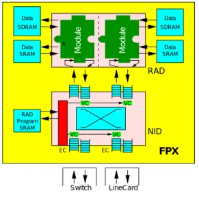
The FPX contains two FPGAs: the Network Interface Device (NID) and the Reprogrammable Application Device (RAD). The NID interconnects the WUGS, the line card and the RAD via an on-chip ATM switch core. It also provides the logic to dynamically reprogram the RAD. The RAD can be programmed to hold user-defined modules. This fea-ture enables user-defined network modules to be dynami-cally loaded into the system. The RAD is also connected to two SRAM and two SDRAM components. The memory modules can be used to cache cell data or hold large tables. Figure 3 illustrates the major components on an FPX board.
2.3. FPX Modules
User applications are implemented on the RAD as mod-ules. Modules are hardware components with a well-defined interface which communicate with the RAD and other infrastructure components. The basic data interface is a 32-bit wide Utopia interface. Internet packets enter the module using classical IP over ATM encapsulation and seg-mentation into ATM cells. The data bus carries header and payload of the cells. The other signals in the module inter-face are used for congestion control and to connect to mem-ory controllers to access the off-chip memmem-ory. The com-plete module interface is documented in [12].
Usually, two application modules are present on the RAD. Typically, one handles data from the line card to the switch (ingress) and the other handles data from the switch to the line card (egress). As with the Transmutable Telecom System [9], modules can be replaced by reprogramming the FPGA in the system at any time. In the case of the FPX, this functionality occurs via partial reprogramming of the RAD FPGA. A reconfiguration component performs a handshak-ing protocol with the modules to prevent loss of data.
SRAM EC EC Module Switch LineCard VC VC VC VC RAD Module NID FPX SRAM Data Program RAD SDRAM SDRAM Data Data SRAM Data
Figure 3. Components on an FPX board
3. Network Wrapper Concept
Network protocols are organized in layers. On the ATM data link layer, data is sent in fixed size cells. To provide variable length data exchange, a family of ATM Adaption Layers exists. Section 3.2 gives an introduction to the ATM Adaption Layer 5 (AAL5), which is generally used to trans-port IP data over ATM networks. The Network layer uses IP packets to support routing through multiple, physically separated networks.
Components have been developed for the FPX that al-low applications to handle data on several protocol layers. Similar circuits have been implemented in static systems to implement IP over Ethernet [6]. Unlike systems that of-fload protocol processing to a co-processor [3], this library allows all packet processing functions to be implemented on the same chip.
Translation steps are necessary between layers. A classi-cal approach creates components for each protocol transla-tion. Such a system would instantiate one entity to translate data from the cell level to the AAL5 frame level. Such an implementation would also need to have a component to perform the reverse step as well. In our approach, we com-bine these two translation units into one component, which has four interfaces as a consequence: two to support the lower level protocol and two to provide a higher level inter-face, respectively. Also the two components are connected to each other. This is useful to exchange additional infor-mation or to bypass the application. The latter is done in the cell processor (section 3.1).
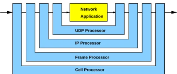
When an application module is embedded into a proto-col wrapper, the new entity surrounds the user’s logic like the letter U (figure 1). Regarding the data stream, the
ap-plication only connects to the translating component, which wraps up the application itself. Therefore we will refer to the surrounding components as wrappers.
To support higher levels of abstraction, the wrappers can be nested. Since each has a well defined interface for an outer and an inner protocol level, they fit together within each other, as shown in(figure 1). As a result, we get a very modular design method to support applications for dif-ferent protocols and levels of abstraction. Associating each wrapper with a specific protocol, we get a layer model com-parable to the well known OSI/ISO networking reference model. This modularity gives application developers free-dom to implement functions at several protocol layers in their designs. They can interface their logic to a wrapper with the level of abstraction appropriate for their specific application. User-level applications, for example, can com-pletely ignore handling of complicated protocol issues, like frame boundaries or checksums.
3.1. Cell based processing
At the lowest level of abstraction, data is sent in fixed length cells. Applications or wrappers working at this level typically process the ATM header and filter cells by their virtual channel.
The behavior of an FPX module can be modified via con-trol cells. Concon-trol cells are ATM cells with a well-defined structure and provide a communication path between an ex-ternal controller (e.g. software) and the on-chip modules. This can be used to remotely configure module, for exam-ple. Control cells are secured with a 16-bit CRC.
A standard control cell format has been developed to transmit information between software [11] that controls the FPX. Control cells to the NID are used to setup the routes between the line card, the switch and user applications on the RAD. They are also used to upload new application modules to the RAD.
Control cells to the RAD contain an additional field, the module ID, to address the application module. Some stan-dard opcodes are understood by all FPX modules. Com-mands to change the VPI/VCI registers, for example, are supported by all modules, so that they can operate on any virtual channel.
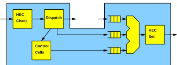
The wrapper on the lowest level is the cell processor (fig-ure 4). It performs cell level operations that are common to all FPX modules. First, incoming ATM cells are checked against their Header Error Control (HEC) field, which is part of the 5 octet header. An 8 bit CRC is used to prevent errored cells from being misrouting. If the check fails, the cell is dropped.
Cell that are accepted are next processed by their virtual channel information. The cell processor distinguishes be-tween three different flows:
Check Control Cells HEC Set Dispatch HEC
Figure 4. Cell processor
1. The cell is on the data VC for this module. In this case, the cell will be forwarded to the inner interface of the wrapper and thus to the application.
2. The cell is on the control cell VC and is tagged with the correct module ID. Control cells are processed by the cell processor itself. This mechanism is covered later in this section.
3. None of the above, i.e. this cell is not destined for this module. These cells are bypassed and take a shortcut to the output of the cell processor.
The cell processor provides three FIFOs to buffer cells from either of the three paths. A multiplexer combines them and forwards the cells to their last stop. Just before they leave the cell processor, a new HEC is computed.
The control cell handling function inside the cell proces-sor is designed to be very flexible, thus making it easy for application developers to extend its functionality to fit the needs of their modules. User applications typically support more control cell opcodes than the standard codes, usually to configure the module or to interact with software compo-nents, so extendibility was an important goal in the design of the cell processor. The control cell processing framework performs CRC check and generation functions, buffering of common data structures, and implements a mechanism to share common information. A master state machine waits for control cells destined for this module and then stores opcodes, user data, the CM field and sequence number. At the same time it also checks the control cell CRC. Every opcode has its own state machine. So adding a new com-mand does not interfere with existing ones. Every state ma-chine polls the master state, if a control cell with a valid CRC has been read and becomes active on its opcode. For any incoming control cell (request), a response cell should be sent, if the command has been processed successfully. Because there is a state machine for every opcode, which generates its own response cell, a multiplexer takes care of forwarding the correct one to the output port. Finally, every new control cell gets a valid CRC before it is forwarded to the cell multiplexer.
3.2. Frame based processing
To handle data with arbitrary length over ATM networks, data is organized in frames, which are sent as multiple cells. Several adaption layers have been specified ([1, 2]), which differ in the property of being connection-oriented or con-nectionless, in the ability to multiplex several protocols over one virtual channel and to reorder cells during transmission. ATM Adaption Layer 5 (AAL5) is widely used for IP networks [10])and is also one of the simpler protocols. In AAL5 datagrams or frames of arbitrary length are put into protocol data units (PDU).
The frame processor is a wrapper module for the FPX to handle AAL5 frame data. Its interface is designed to give application modules a more abstract view of the data. The frame processor replaces the Start-of-Cell signal with three signals, namely Start-of-Frame (SOF), End-of-Frame (EOF) and Data-Enable (DataEn).
As the name indicates, SOF indicates the transmission of a new frame. Note that the Header-Error-Control (HEC) is not available with this wrapper. It is assumed that only valid ATM cells are passed to this wrapper and that valid HECs are generated from outgoing cells.
The Data-Enable signal indicates valid payload data. It can be seen as an enable signal for the data processing ap-plication. It is completely independent from the cell struc-ture. Applications can therefore resize frames or append data easily. They can also generate new frames. Note that the Data-Enable signal is not asserted when padding is sent, since it is not considered a part of the frame. The End-of-Frame signal is asserted with the last valid payload word being sent. Applications thus have enough time to start ap-pending data to a frame, if necessary.
After the EOF signal, two more words are sent. These 8 octets represent the AAL5 trailer, including some addi-tional information for this wrapper, that is used to recreate the length and the CRC field. It is essential that applica-tions copy and forward the two additional words.
3.3. IP Packet Processing
The Internet Protocol is a very popular communication means across several networks. Protocols built above IP, including UDP and TCP, are used to send datagrams and establish reliable connections, respectively.
The IP processor was developed to support Internet Pro-tocol based applications. It inherits the signalling interface from the frame processor and adds a Start-of-Payload (SOP) signal, to indicate the payload after the IP header, which can be of variable length. This wrapper serves three primary functions:
1. It checks the IP header integrity to verify the correct-ness of the header checksum. Corrupt packets are
dropped.
2. It decrements the Time To Live (TTL) field. As of RFC 1812 [4] all IP processing entities are required to decrement this field. Once this field reaches zero, the packet should not be forwarded any more. This is to prevent packets from looping around in networks due to mis-configured routers.
3. It recomputes the length and the header checksum on outgoing IP packets.
An IP header usually has the length of 20 bytes, or 5 words.1
The whole header must be processed by a checksum cir-cuit before any decision about its integrity can be made. The IP Processor computes and then compares the header checksum. On a failure, the IP-packet is dropped by not propagating any signal to the application. If the Time-To-Live field of an incoming packet is already zero, the packet is also dropped and an ICMP packet is sent instead. Oth-erwise the TTL field is decremented by one. Outgoing IP packets are buffered so that the actual length can be deter-mined. The corresponding field in the header and the header checksum are set accordingly. Therefore a whole packet has to be buffered, before it can be sent out.
To save and share resources with other wrappers, the IP wrapper understands a protocol to update the contents of bytes earlier in the packet. The IP processor can apply changes to the packet payload for fields, such as a header, that were set when the packet originally streamed through the hardware. Update commands are optional and are in-serted between the last payload word (EOF signal asin-serted hi) and the AAL5 trailer. An unused bit (15) in the AAL5 length field is used to indicate update words or the start of the trailer. The length field is also used to hold an error code, so that packets can be dropped before they are sent out. Update words contain a 16 bit update field and a 15 bit update offset address. The 16 bit word at the offset address in the buffer is replaced by the update field.
3.4. UDP Datagram Processing
UDP is an IP protocol used for connectionless and un-reliable communication between processes based on data-grams. The UDP processor is a wrapper that supports this protocol. This wrapper computes and generates the UDP checksum and the length field in the header for outgoing datagrams. Incoming datagrams are also checked for the checksum, but the result is only available after the whole packet has passed through the wrapper. The UDP processor uses similar signals as the IP processor. It replacing the SOP
1This applies to the vast majority of IP packets that do not contain any
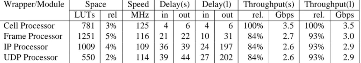
Wrapper/Module Space Speed Delay(s) Delay(l) Throughput(s) Throughput(l) LUTs rel MHz in out in out rel. Gbps rel. Gbps
Cell Processor 781 3% 125 4 6 4 6 100% 3.5 100% 3.5
Frame Processor 1251 5% 116 21 22 10 31 84% 2.7 93% 3.0 IP Processor 1009 4% 109 36 39 24 197 84% 2.6 93% 2.9 UDP Processor 550 2% 114 39 44 27 202 84% 2.6 93% 2.9
Table 1. Implementation results of the wrappers
signal with the Start-of-Datagram (SOD) signal. Applica-tions can simply process datagrams or even generate new ones without the need to interpret or generate UDP headers. To determine the correct checksum for outgoing data-grams, the whole packet is buffered. Since the IP processor already buffers a full IP packet, it would have been a waste of on-chip resources to implement an additional buffer just for the UDP wrapper. Instead, the UDP processor informs the IP processor about necessary updates in the packet and leaves the buffering to that wrapper.
4. Implementation Results
Our framework is designed for the FPX. The system clock on the FPX is 100 MHz and the FPGA used is a Xilinx Virtex 1000E-7. Table 1 summarizes the size (in lookup ta-bles and relative to RAD chip-size) and the maximum speed of our components. It also gives some information about the delays in clock cycles of data passed through the wrappers and the throughput. These results have been measured by sending UDP packets of one cell-size (s) and with 512 bytes of payload (l). Delays are split up into delays before (in) and after (out) an embedded application.
5. Conclusions
We have presented a framework for IP packet processing applications in hardware. Although our current implemen-tation was created for use in the Field Programmable Port Extender, the framework is very general and can easily be adapted to other platforms. A library of Layered Protocol wrappers has been implemented. Each handles a particular protocol level. By using an entity that surrounds an applica-tion module (a U-shape wrapper), the related logic to con-vert to and from a protocol are linked, increasing the flexi-bility and reducing the number of cross-dependencies. The common interface between layers also lowers the learning curve.
The framework is useful for developers of networking hardware components. Applications themselves don’t have to take care about network protocol issues. The complete IP processing framework only utilizes 14% of the RAD
FPGA on the FPX, leaving sufficient space to implement user-defined logic.
References
[1] B-ISDN ATM adaptional layer AAL Functional Descrip-tion. CCITT: Recommendation I.362, 1991.
[2] B-ISDN ATM adaptional layer AAL Specification. CCITT: Recommendation I.363, 1991.
[3] E. A. Arnould, F. J. Bitz, E. C. Cooper, H. T. Kung, R. D. Sansom, and P. A. Steenkiste. The design of Nectar: A net-work backplane for heterogeneous multicomputers. In
Pro-ceedings of the Third International conference on Architec-tural support for Programming Languages and Operating systems (ASPLOS-III), pages 205–216, 1989. Also available
as Technical Report CMU-CS-89-101, School of Computer Science, Carnegie Mellon University, Pittsburgh.
[4] F. Baker. Requirements for IP version 4 routers. Internet RFC 1812, June 1995.
[5] T. Chaney, J. A. Fingerhut, M. Flucke, and J. S. Turner. De-sign of a gigabit ATM switch. Technical Report WU-CS-96-07, Washington University in St. Louis, 1996.
[6] H. Fallside and M. J. S. Smith. Internet connected FPL. In Proceedings of Field-Programmable Logic and
Applica-tions, pages 48–57, Villach, Austria, Aug. 2000.
[7] J. W. Lockwood, N. Naufel, J. S. Turner, and D. E. Tay-lor. Reprogrammable Network Packet Processing on the Field Programmable Port Extender (FPX). In Proceedings
of FPGA 2001, Monterey, CA, USA, Feb. 2001.
[8] J. W. Lockwood, J. S. Turner, and D. E. Taylor. Field pro-grammable port extender (FPX) for distributed routing and queuing. In Proceedings of FPGA 2000, pages 137–144, Monterey, CA, USA, Feb. 2000.
[9] T. Miyazaki, K. Shirakawa, M. Katayama, T. Murooka, and A. Takahara. A transmutable telecom system. In
Proceed-ings of Field-Programmable Logic and Applications, pages
366–375, Tallinn, Estonia, Aug. 1998.
[10] P. Newman et al. Transmission of flow labelled IPv4 on ATM data links. Internet RFC 1954, May 1996.
[11] T. Sproull, J. W. Lockwood, and D. E. Taylor. Control and configuration software for a reconfigurable networking hardware platform. In submitted to Globecom 2001, San Antonio, TX, USA, Nov. 2001.
[12] D. E. Taylor, J. W. Lockwood, and S. Dharmapurikar. Generalized RAD Module Interface Specification on
the Field Programmable Port Extender (FPX). http://