Mechanical Testing
Mechanical testing is a general term which refers to a broad range of activity involved with the determination of mechanical properties and behavior of material, structures and machines. Typically, this involves applying some type of stimulus and measuring a response. The stimulus may be either static or dynamic in nature and may act in a localized or a distributed manner at single or multiple locations. In a similar way, the response measurement may be made at one or more points or in a distributed manner.
Expanding on this definition, mechanical testing is the process of applying forces, pressures, displacements, heat, or similar stimuli to a mechanical system and then measuring its response. The objective, or course, is to characterize the behavior of the system either in order to obtain assurance of the performance or to verify the one hand, mechanical testing may be carried out primarily to verify the overall performance of a mechanical system, i.e., the load carrying capability of an aircraft wing, or the thrust production of a rocket motor. On the other hand, mechanical testing may be used to verify the appropriateness or accuracy of a particular theory. In this case, the testing is usually directed at a simplified component or model that may actually bear no outward resemblance to a practical design. A third case could be defined to include those tests carried out primarily to characterize the mechanical properties of a new material. As with the second case, the testing usually involves working with rather abstract specimens which bear no resemblance to a practical product.
In all of these situations, the test methodology may be either deterministic or probabilistic in nature. In the first case, the approach is to carry out thorough and extensive tests with a single or at most a very few specimens which are assumed to be representative of a larger set. This is often preferred when the specimen is costly or the test setup is complex. The other approach is to use a large number of nominally identical specimens which are assumed to constitute a suitable subset or sample of the larger set of all possible specimens. Statistical methods are then used to analyze the data and to draw conclusions about the properties of the whole set.
In the Structures Lab courses, the major emphasis will be directed towards examining the various techniques, instruments and interpretative methods for carrying out mechanical testing. At the same time, this knowledge will be used to perform various mechanical tests for the
purpose of verifying the theories developed in the companion courses. Relatively little emphasis will be placed on examining methods for overall performance testing.
Test Machines
Test machine or testing machines is the name used to refer to any one of a variety of devices for applying a controlled load to a specimen. The loads may range from a few grams to millions of pounds using machines currently available. The loads may either be static in nature (changed slowly from one level to another), or may vary rapidly at rates up to tens or hundreds of cycles per second (Hertz).
In general there are two principal components to a test machine: a loading mechanism, and a weighing or load-measuring system. A number of different approaches have been used in the design on each of these components, and consequently, it is logical to describe test machine designs by examining each component separately. The section will be concluded by describing the characteristics of several of the test machines available in the Aerospace Engineering laboratories.
Loading Mechanisms
Load generation in most test machines is done either hydraulically or mechanically. Electromagnetic and thermal techniques have been employed in a few specialized cases.
Hydraulic:
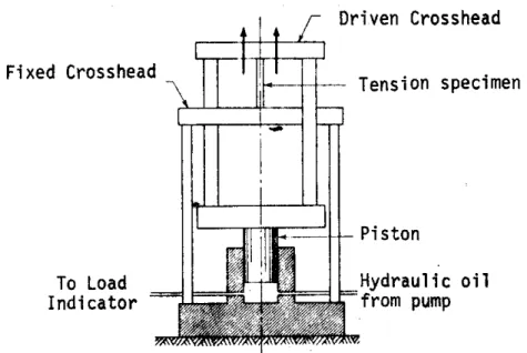
Hydraulic loading mechanisms use a piston in a cylinder actuated by pressurized oil or hydraulic fluid. As shown in Fig. 1, the cylinder is bored in a large massive structure which forms the stationary base of the test machine. For simplicity and ruggedness, the piston is design for unidirectional operation, that is, for applying load in only one direction. It is connected to a moving table on which the test specimen can be placed. A fixed crosshead is supported above on columns attached to the base so that a compressive load can be applied to a specimen located between the table and crosshead. The test machine “daylight space” is the maximum vertical opening between the table and crosshead. Typically, the maximum piston stroke is about 2”, and in order to accommodate a variety of specimen heights, the fixed crosshead can be adjusted vertically. This is usually done by using large threaded rods for the supporting columns and fitting motorized nuts in the crosshead. Tension loads can be applied if a driven crosshead attached to the table and piston is located above the fixed crosshead. Specimens are then attached between the fixed and driven crossheads. This type of design is frequently referred to as a Universal Test Machine because of its ability to generate either tension or compression loads. Hydraulic design are usually the least expensive in the larger machine sizes and are capable of generating the highest loads available.
Figure 1. Universal Hydraulic Testing Machine
The load control is obtained by regulating the hydraulic pressure in the cylinder beneath the piston. This is done by means of two needle type flow control valves. One valve is connected between pump and the cylinder and is used to control the buildup of pressure. The other is connected between the cylinder and the reservoir and is used to control the bleedoff of pressure. The two valve functions are sometimes incorporated in a single control valve, or in other designs the control unit is simply fitted with separate “loading” and “unloading” valves. Due to the double acting nature of the controls and the small leakage always present around the piston, it is
nearly impossible to maintain a constant load or crosshead position. However, the load can usually be applied smoothly especially at high levels.
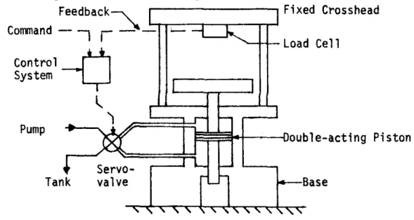
The newest type of hydraulic test machine is the electrohydraulic design. The load is generated in the same manner as above but the control is accomplished by means of an electrically activated 4-way valve. A typical configuration is shown in Fig. 2. Due to the reversible 4-way control valve, it is now possible to use a double acting hydraulic piston or “actuator” which is capable of forcefully advancing or retracting. This is accomplished because the control valve can continuously vary the flow from the pump to either side of the piston while connecting the opposite side to the tank. As a result, it is not necessary to provide separate tension and compression spaces. Both tensile and compressive loads can be applied to the specimen without having to relocate or reattach it. In fact, the load can obviously be reversed from tension to compression or vice versa during the same test.
Figure 2. Typical Electrohydrualic Test machine
Control of an electrohydraulic machine is considerably more complex but the resulting capabilities are far greater. Since the valve is electrically operated, it can readily be controlled by electronic circuitry or even a computer. The typical control systems used a concept called feedback control that is commonly employed in a large number of process and industrial control applications as well as for many purely electronic circuit designs. In this approach, an electrical signal generated by the weighing system is fed back to the control system where it is compare with a command signal representing the desired load. If the difference or error signal is zero, the valve position remains unchanged, but if it is nonzero, the valve will be electrically driven in a direction to reduce the error. With proper stable adjustment, the load will closely follow the valve specified by the command signal which itself may be generated by a manually operated knob, a function generator, a computer, or a previously recorded signal (on magnetic tape, for example). In typical test machine designs, the valve can be driven at frequencies up to several tens of Hertz so that dynamically varying loads can be generated. This is invaluable for fatigue and fracture testing. On a more general note, the feedback signal need not be proportional to load but can be derived from actuator displacement, velocity, or to specimen strain, for example. These variables then become the controlled or independent variable in the test. As a final note, this same technology was originally developed to provide boost forces for aircraft control
surfaces in the early 1950’s and is used today in “fly-by-wire” designs in which the only pilot connection to a control surface is by means of the electrical command signal.
Mechanical:
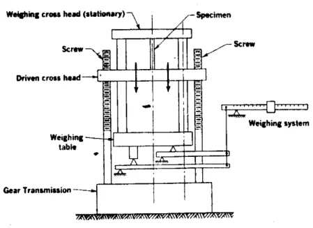
Mechanical loading mechanisms employ a screw system to generate a load in much the same way as a screw-jack operates. In the most common configuration, as shown in Fig. 3, the load is produced by the movement of a driven crosshead towards or away from a stationary crosshead or the machine table. The driven crosshead is activated by threaded supporting columns which are rotated by a motor and gear drive mounted in the machine base. The figure shows a “universal” configuration with separate spaces for compression and tension. Most modern machines use a single opening and rive the crosshead in either direction. This is simpler but requires special nuts in the crosshead which do not exhibit any mechanical hysterisis or slack when the load is reversed. Mechanical or screw-jack type machines are generally limited to less than about 500,000 lbs. capacity and are more costly than hydraulic machines in the larger capacity ranges. Mechanical designs are often cheaper in the small sizes of less than about 2000 lbs. capacity. Mechanical machines are somewhat harder to control at very high loading levels but they can hold a constant crosshead position easily and thus can be used to maintain loads for long periods of time.
Figure 3. Typical Mechanical (Screw-jack) Test Machine
Control of mechanical loading mechanisms can be accomplished in the simplest case by using a reversible variable speed motor with mechanically or electrically selectable gear ratios. A more complex approach involves using a form of synchro control called and “amplidyne”. The shaft position of a synchro motor is slaved to a much smaller synchro transmitter which provides the control input. As the shaft of the synchro transmitter is rotated manually, the slaved synchro motor follows exactly. This motor is connected through gearing to drive the screw columns. This makes for simple and convenient manual control. Automatic control can be provided by rotating the transmitter with a small geared clock motor or else the synchro signals can be electrically created in a computer controlled synchro synthesizer.
Other:
Many other techniques have been used to produce controlled forces but few are commonly used in test machine designs. Two techniques deserve mention, however. Electromagnetic actuators similar in concept to audio speakers have been employed to generate forces for test purposes. The single advantage in this approach is the dynamic performance obtained, but this has in recent designs been nearly equalled by electrohydraulic machines. The disadvantage is that maximum forces are typically in the range of a few hundred pounds. Another approach involves using the thermal expansion of a confined material to produce a force. A suitable material is slowly heated or cooled to produce an expansion or contraction. If it along with the specimen is confined between two rigid crossheads, the result will be a compressive or tensile load in both the specimen and the driving material. This approach resembles the mechanical screw type machines, but it is capable of much slower loading rates with little of the hysterisis often encountered in mechanical machines because of the screw/nut interface.
Weighing Mechanisms
Weighing or load measuring mechanisms are employed in test machines to indicate the magnitude of the force generated. In contrast to the case for loading mechanisms, weighing systems are considerably more varied in concept although the current designs almost universally utilize electrical resistance strain gage load cells. The different approaches are described in the following sections.
Mechanical:
Mechanical weighing systems employ an arrangement of beams, levers, and balances to indicate load in much the same way that balance beam platform weighing scales operate. The schematic in Fig. 3 shows a simple balance beam and poise system used with a screw type loading mechanism. This requires manual positioning of the pose and is very cumbersome. The approach is more commonly designed with an automated means for positioning the poise. One method is to attach the poise to a threaded rod or lead screw running the length of the balance beam and driven by a small electric motor. The position of the beam is sensed electrically and if not in balance, current is supplied to the motor to move the poise in a direction to return to a balanced state. This principle of measurement in which the system is always returned to (or maintained in) the same balanced state is often referred to as a “null balance” measurement and can be implemented in either mechanical or electrical terms. The balance beam approach often yields high accuracies and by change of poise weight can easily be extended in range. It is, however, quite slow. The concept is often used in wind tunnels to measure model forces (the systems are referred to as “tunnel balances”).
The balance beam can be replaced with a directly calibrated indicating system. In this approach the scaled down force proportional to load that is transmitted by the beam is applied to a load sensing element and the resulting deflection is used to indicate the load. A common method is to use a pendulum which swings up in response to a moment generated by the beam force. The pendulum position is indicated on a large load dial. Elastic members such as
cantilevered beams and torque tubes can also be used. In these cases the load is indicated by the resulting elastic deformation produced by the scaled forces.
Hydraulic:
Hydraulic weighing systems are of two main types. The first type is usable only with hydraulic loading systems and simply involves measuring the fluid pressure in the cylinder beneath a single acting piston. The pressure is sensed by a conventional pressure gage whose dial is calibrated in units of load. (The most common gages, called bourdon tube types, employ a hood shaped thin tube which when pressurized tends to uncurl and by means of gears and
linkages to rotate a dial pointer.) This direct approach is by far the simplest, but due to friction forces between the piston and cylinder, the maximum in accuracy may not be obtained. This concept is illustrated in Fig. 1. Note that the method cannot be used with bi-directional cylinders or actuators in which an opposing pressure may be acting on the other side of the piston.
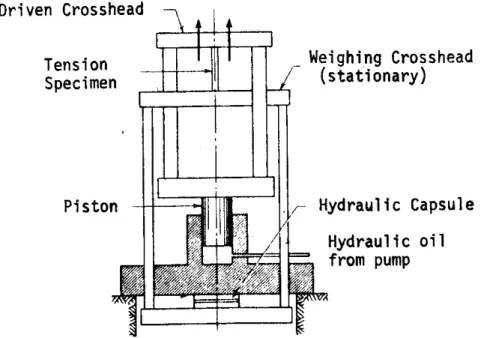
Figure 4. Hydraulic Test Machine with Load Weighing Capsule
The other type of hydraulic weighing system is completely separate from the loading mechanism. A hydraulic capsule (a sealed bellows, for example) is placed somewhere in the load path and the internal pressure is sensed by a pressure gage or transducer. As shown in Fig. 4, the capsule can be located in a position to measure the full load reacted by the stationary crosshead. The use of a capsule avoids the problem of piston friction noted above and a similar simple bourdon tube pressure gage can also be used to indicate the load.
For either type, several variations in the load indicating system have been developed. One approach is actually a combination of hydraulic and mechanical techniques. The hydraulic pressure is used to activate a small piston which in turn deflects a balance beam. The beam can be automatically balanced as noted earlier or it can be coupled to a pendulum. This approach is often used because various indicator ranges can be incorporated simply by varying the balance beam fulcrum location. Another approach involves using a bourdon tube in a null balance configuration. A pneumatic actuator (bellows) is connected to the tip of the bourdon tube and is used to hold the tip at its undeflected or null position. Thus, as the load increases, more force must be exerted by the bellows to maintain the bourdon tube tip at the null position. The load indication is derived from the deflection of an elastic member in the bellows load path. This
design is called a “Tate-Emory” weighing system and has the advantage of allowing or change in fluid volume takes place in the bourdon tube.
Strain Gage Load Cells: By far the most popular approach used in current test machine weighing systems is to employ strain gage type force transducers (or load cells) to measure the loads. These units will be described in much greater detail in subsequent sections when strain measuring techniques are discussed. Basically, however, the units consist of an elastic load sensing element whose resulting deformation under load is sensed by electrical resistance strain gages. The resistance change is detected by simple electronic circuitry and amplified to either operate a large dial indicator or a digital display. The signal is also available for recording or processing by a computer. These load cells are generally bi-directional so they are ideally suited to electrohydraulic test machines or other machines with a single test space.
Test Machine Characteristics
Hydraulic and mechanical test machines have other distinguishing characteristics that may be more or less desirable for specific applications. Some of these have already been noted. Two, however, deserve special treatment.
Prescribed Variable:
Hydraulic and mechanical test machines differ in their loading characteristics in one major way. Mechanical designs utilize a prescribed displacement of a crosshead to produce a load on a confined specimen. In this case the displacement is the independent variable and the resulting force depends upon the stiffness of the specimen:
F = ksx
where, ks is the specimen stiffness and x is the crosshead displacement. The forces are higher for stiffer specimens and vice versa. Hydraulic designs on the other hand utilize hydraulic pressure to produce a prescribed force on the confined specimen. In this case, force is the independent variable and the resulting deflection depends on the specimen stiffness.
x = F/ks
The deflections are thus lower for stiffer specimens and vice versa.
Electrohydraulic test machines are somewhat unique is this respect because their characteristics can be changed depending on the choice of control variable. If the load as measured by a load cell is used as the feedback signal, then load is the independent variable and the machine behaves like a conventional hydraulic machine. On the other hand, if actuator stroke is used for the feedback signal, then displacement is the independent variable and the machine behaves like a screw type design.
These characteristics are particularly important depending on the test requirements. Hydraulic machines are preferable in applications where a relatively constant load must be maintained even though small incremental or continuing deformation occurs. This is desirable, for example, in certain creep tests where it is necessary to measure the specimen elongation with time while under a constant load at an elevated temperature. Mechanical screw type machines are preferable in applications where load instabilities exits, that is, in situations where an
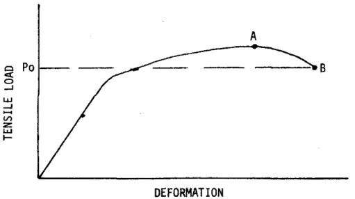
increment in load produces deformations that can only be maintained if the load is reduced. This occurs in column buckling tests as well as in tension tests of material samples to determine their mechanical properties. The latter case is illustrated in Fig. 5 for a typical ductile material. If the tensile load is prescribed (hydraulic machine) then the vertical axis marks the independent
variable. The situation is stable until the loading reaches A. Beyond this point, the specimen can support no further increase in load so that what happens is that path A-B is never recorded. Instead, the specimen rapidly elongates and failure occurs almost instantly. Another way of visualizing this is to note that for loads above Po, there are two equilibrium deflections for a given load. It is thus possible at any time for the specimen to jump over to a larger displacement state provided the incremental force is momentarily available (due for instance to a perturbation from outside forces). The key here is the multivalued nature of the behavior for prescribed loading. If a mechanical test machine is used, the displacement marked on the horizontal axis is the independent variable. In this case there is no multivaluedness and instability is not a
problem. Instead, as the crosshead is advanced, the load on the specimen rises to A and then falls off to the failure point at B.
Figure 5. Typical Load-Deflection Curve for a Ductile Material
Machine Stiffness:
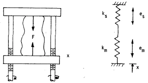
A more subtle factor in test machine operation is the mechanical stiffness of the machine through the load path. Two problems can arise if the machine is not very stiff compared to the specimen. First, for a mechanical screw type machine, this finite stiffness acts like a spring in series with the specimen whose stiffness can also be represented by another spring as shown in Fig. 6. If the crosshead motion is x and the specimen load is F, then it follows that
kx e k e k F= s s= m m=
And the relative deflections of the specimen and machine are thus given by: Specimen: es=F/ks
Machine: em=F/km
It also follows that:
x = F/k= F/
[
kskm/(
ks +km)
]
Thus the specimen deflection (shortening in this case) is given as:(
s m)
m s s s F k xk k xk k k e = / = / = / +or by taking time derivatives, the deflection rate is:
(
s m)
ms xk k k
e = / +
This result show that for a finite machine stiffness, the actual specimen deflection will be less that the crosshead motion which is prescribed. For example, it the specimen and machine are of equal stiffness, the actual deflection rate will be one half the set crosshead rate. Generally, it is desirable to use a machine whose stiffness is at least an order of magnitude or better than the specimen stiffness.
Figure 6. Stiffness Analysis of a Typical Test Machine
The second factor concerns the buildup of internal or strain energy within the frame of the test machine. With reference to the above results, the strain energy in the test machine is the strain energy in the equivalent spring:
( )
m m m e F k k U / 2 1 2 1 2 = 2 =The stiffer the machine, the less strain energy is stored for a given load. The presence and availability of this energy can be a cause for concern in testing where instabilities are present. Given the right trigger, such as an outside impulse or shock, this energy is available to quickly upset the equilibrium of the specimen and possible result in its sudden failure.
Machines that are very stiff are called “hard” test machines, while those with a low stiffness are referred to as “soft”. With a very hard screw type machine it is often possible to watch the ultimate tensile failure of a ductile specimen as a gradual tearing apart of the material. The same process observed in a soft machine is usually a rapid and sometimes explosive fracture that is impossible to see with the unaided eye.