2016
Accessible Remote Testbed for Cyber-Physical
Systems Security of the Smart Grid
Sujatha Krishnaswamy
Iowa State University
Follow this and additional works at:https://lib.dr.iastate.edu/etd Part of theComputer Engineering Commons
This Thesis is brought to you for free and open access by the Iowa State University Capstones, Theses and Dissertations at Iowa State University Digital Repository. It has been accepted for inclusion in Graduate Theses and Dissertations by an authorized administrator of Iowa State University Digital Repository. For more information, please [email protected].
Recommended Citation
Krishnaswamy, Sujatha, "Accessible Remote Testbed for Cyber-Physical Systems Security of the Smart Grid" (2016).Graduate Theses and Dissertations. 15743.
Accessible remote testbed for cyber-physical systems security of the smart grid by
Sujatha Krishnaswamy
A thesis submitted to the graduate faculty
in partial fulfillment of the requirements for the degree of
MASTER OF SCIENCE
Major: Computer Engineering
Program of Study Committee: Manimaran Govindarasu, Major Professor
Doug Jacobson Venkataramana Ajjarapu
Iowa State University Ames, Iowa
2016
DEDICATION
Dedicated to my beloved mother (Mrs. Rajalakshmi Subramanian), grandfather (Mr. Subramanian Iyer) and grandmother (Mrs. Saraswathi Subramanian) …
TABLE OF CONTENTS
LIST OF FIGURES ... vii
LIST OF TABLES ... viii
ACKNOWLEDGMENT ... ix
ABSTRACT ... x
CHAPTER 1 INTRODUCTION ... 1
1.1 Smart Grid – A Cyber-Physical System ... 1
1.2 Smart Grid Cyber Threats ... 4
1.3 CPS Security Testbed ... 6
1.3.1 DETER Testbed ... 6
1.3.2 powerNET Testbed ... 7
1.3.3 National SCADA Testbed ... 7
1.3.4 WSU Smart Grid Testbed ... 7
1.3.5 NREL Smart Grid Testbed ... 8
1.3.6 ISU PowerCyber Testbed ... 8
1.3.7 Other CPS Security Testbed ... 9
1.3.8 Comparison of Testbed capabilities ... 9
1.4 Thesis Motivation ... 10
CHAPTER 2 PowerCyber - REMOTE ACCESS FRAMEWORK ... 14
2.1 PowerCyber: Testbed Overview ... 14
2.1.1 PowerCyber Testbed Architecture ... 14
2.1.2 PowerCyber Supported Use Cases ... 15
2.1.2.1 Vulnerability Assessment ... 15
2.1.2.2 Impact Analysis and Mitigation Research ... 16
2.1.2.3 Testbed Federation ... 16
2.1.2.4 Attack-Defense Exercises & Operator training ... 16
2.1.2.5 Model Development ... 16
2.1.2.6 Remote Access ... 17
2.2 Remote Access Framework ... 17
2.2.1 Implementation Architecture ... 19
2.2.1.1 Front-end Web Server ... 20
2.2.1.2 Backend Orchestration Framework ... 20
2.2.1.3 Models and Libraries ... 20
2.2.2 Design Flow ... 21
2.2.2.1 User Interface Design ... 23
2.2.2.2 Experiment Automation ... 24
CHAPTER 3 STORY-BOARDS AND CASESTUDY ... 27
3.1 Story-Board Constructs ... 27
3.1.1 Story Board 1 ... 27
3.1.2 Story Board 2 ... 28
3.1.4 Story Board 4 ... 29
3.1.5 Story Board 5 ... 29
3.1.6 Story Board 6 ... 30
3.1.7 Story Board 7 ... 30
3.2 Case Study ... 31
CHAPTER 4 USER COMMUNITY ENGAGEMENT STUDIES ... 53
4.1 Academic user engagement ... 53
4.1.1 Background ... 53
4.1.2 Experimentation Overview ... 54
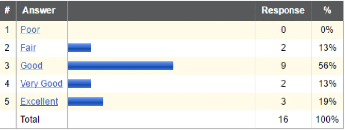
4.1.3 User Survey & Evaluation ... 58
4.1.4 Testimonials ... 66
4.2 Industrial user engagement ... 66
4.2.1 Background ... 66
4.2.2 Product Overview ... 66
4.2.3 Phase 1 Engagement ... 67
4.2.4 Phase 2 Engagement ... 67
CHAPTER 5 CONCLUSION & FUTURE WORK ... 69
5.1 Conclusion ... 69
5.2.1 Developing a library of models, attack vectors ... 70
5.2.2 Expanding user community ... 70
5.2.3 Improving the programmability ... 70
5.2.4 Federation ... 70
LIST OF FIGURES
Figure 2.1 PowerCyber CPS Security Testbed Architecture ... 14
Figure 2.2 Remote Access Framework ... 18
Figure 2.3 Remote Access Framework -Implementation Architecture ... 19
Figure 2.4 Design Flow for User Interface ... 23
Figure 2.5 Design Flow for Experiment Automation ... 25
Figure 4.1 RAS on G2 coordinated attack ... 55
Figure 4.2 RAS on G1 coordinated attack ... 56
Figure 4.3 RAS on G3 coordinated attack ... 57
LIST OF TABLES
Table 1.1 Testbed Capability comparison ... 9
Table 4.1 University Selection ... 58
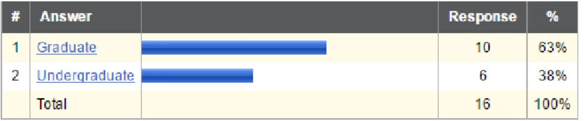
Table 4.2 Level of education ... 58
Table 4.3 Majors selection ... 59
Table 4.4 Cybersecurity proficiency ... 59
Table 4.5 Power engineering proficiency ... 60
Table 4.6 User manual clarity ... 60
Table 4.7 Experiment documentation clarity ... 61
Table 4.8 Remote access framework – Ease of use ... 61
Table 4.9 Improvisation suggestions from users ... 62
Table 4.10 Experimentation takeaway ... 63
Table 4.11 Experimentation enhancement ... 64
ACKNOWLEDGMENTS
I would like to express my sincere thanks to Dr. Manimaran Govindarasu and Aditya Ashok for their guidance and support throughout the course of this research. I would like to thank my committee members, Dr. Doug Jacobson and Dr. Venkataramana Ajjarapu for consenting to be a part of Program of Study committee.
In addition, I would also like to thank my colleagues, the department faculty and staff for making my time at Iowa State University a wonderful experience. I want to also offer my appreciation to those who were willing to participate in my surveys and observations, without whom, this thesis would not have been complete.
ABSTRACT
With growing concerns for cyber security of critical infrastructures like the power grid, Cyber-Physical Systems (CPS) security testbeds are essential in providing controlled testing environments for evaluating and validating novel CPS security tools and technologies, thereby accelerating the transition of research to industrial practice. The engineering of such testbeds requires significant investments in money, time and modeling efforts to provide a scalable, high-fidelity, realistic attack/defense platform. Therefore, there is a strong need in research community, academia and industry to create remotely accessible testbeds that enable access to a broader user community through frameworks that support a range of use-cases such as vulnerability assessments, impact analysis, product testing, attack-defense exercises, and operator training. This thesis will focus on remote access framework that has been implemented on PowerCyber - CPS security testbed for Smart Grid at Iowa State University.
Firstly, this thesis introduces the motivation for enabling remote access on PowerCyber by reviewing state-of-the-art work in the area along with engineering challenges. Secondly, the thesis elaborates on fundamental building blocks that enable remote experimentation, such as the front-end user interface, backend experiment automation and also describes the architecture, overall design flow and story-board constructs of the remote access framework. Thirdly, the thesis describes a case study of coordinated cyber-attack/defense experimentation on a wide-area power system protection scheme called Remedial Action Scheme using PowerCyber remote access framework. Details of how the remote access framework facilitated diverse user community engagement is included with survey results, use-case studies and user feedback. Finally, the thesis concludes by identifying future work to broaden the scope and features of PowerCyber remote access framework developed.
CHAPTER 1
INTRODUCTION
1.1 Smart Grid – A Cyber-Physical System
Cyber-Physical systems(CPS) are smart systems that consist of computational and physical components that are seamlessly integrated through highly networked communications. These components involve a high degree of complexity at numerous spatial and temporal scales which closely interact to sense the changing state of the real world [6]. Cyber-Physical systems provide the foundation of critical infrastructures such as electric power generation and delivery, personalized health care, emergency response, traffic flow management, etc. These systems form the basis of emerging and future smart services, and improve quality of life in many existing areas as well as many other areas being envisioned. Popular CPS technologies include: Smart Grid, Smart Cities, Internet of Things (IoT), Industrial Internet, etc. [24]
An increasing demand for reliable energy and numerous technological advancements motivated the development of smarter electric grids. The smart grid is an automated, widely distributed, cyber-physical energy production and delivery system integrated with communications and information technology, characterized by two-way flow of electricity and information [7, 25]. Smart grid modernization initiative involves deployment of a variety of individual technical initiatives such as Advanced Metering Infrastructure (AMI), Distribution Automation (DA), Demand Response (DR), Wide-Area Monitoring, Protection and Control systems (WAMPAC) based on Phasor Measurement Units (PMU), large scale renewable integration in the form of Wind and Solar generation, and Plug-in Hybrid Electric Vehicles (PHEV). Of these initiatives, AMI and WAMPAC depend heavily on the cyber infrastructure as
data is transported through several communication protocols to utility control centers and the consumers [26]. The remainder of this section will provide an overview of AMI which is associated with the distribution system, and WAMPAC which is associated with the bulk power system. Advanced Metering Infrastructure (AMI)
AMI is an integrated system of smart meters, communication networks and data management systems (DMS) that enables two-way communication between the utility and the customers. The main goal of AMI is enhancing reliability of electricity generation and distribution while maintaining cost effectiveness. AMI’s are used by utilities to collect current usage information, perform remote meter readings, send real-time pricing data to consumers, detect outages remotely, offer prepaid options to customers and analyze faults within the distribution system. On the other hand, smart meters provide the customers with granular control over their consumption and also facilitate increased integration of Distributed Energy Resources (DER). Demand Side Management (DSM) enabled by AMI exercises direct/indirect control over consumer power consumption [26, 27].
Wide-Area Monitoring, Protection and Control (WAMPAC)
Wide Area Monitoring, Protection and Control systems (WAMPAC) are used to accurately analyze the flow of electricity through bulk power system. WAMPAC leverages the Phasor Measurements Units (PMUs) which provides high sampling rates and accurate GPS-based timing to gain real-time awareness of current grid operations and provide real-time protection and control functions such as Special Protection Schemes (SPS) and Automatic Generation Control (AGC). These are also used by other emerging applications such as oscillation detection, and transient stability predictions. WAMPAC can be subdivided further into its constituent components namely,
Wide-Area Monitoring Systems (WAMS), Wide-Area Protection Systems (WAP), and Wide-Area Control Systems (WAC) [26, 27].
Wide-Area Monitoring Systems
The full potential of PMU data cannot be realized without sharing readings. WAMS provide monitoring techniques by utilizing PMU measurement data that are shared among utilities and other regulators. NASPInet (North American Synchro-Phasor Initiative Network) serves as an example of WAMS deployment, where a separate network was developed for the transmission and sharing of real-time control data [26, 27].
Wide-Area Protection
Wide-Area Protection (WAP) prevents propagation of larger disturbances by collecting system wide information over a wide geographic area to perform fast decision-making and switching actions. One of the most common Wide-Area Protection scheme is Special Protection Schemes (SPS) which is an automation system designed to detect system abnormalities, take corrective actions such as isolating faulted components and maintaining system reliability [28].
Wide-Area Control
Automatic Generation Control (AGC) is a major Wide-Area Control mechanism in the power grid which corrects system generation with respect to load changes to maintain grid frequency at 60 Hz. The AGC functions with the help of tie line flow measurements, frequency and generation data obtained from Supervisory Control and Data Acquisition (SCADA) infrastructure. Other WAC applications such as secondary voltage control, static VAR compensator, inter-area oscillation which use PMU data are still in their nascent stages [26].
1.2 Smart Grid Cyber Threats
As the electric grid evolves into a Smart Grid to provide a reliable, secure and resilient electricity transmission and distribution system, the dependence on cutting edge automation and networking technologies has increased tremendously. The advent of high accuracy, time synchronized, high data rate synchrophasor measurements and other modern substation automation systems over the grid, which are deployed to monitor, control and protect the power grid, have resulted in increased network connectivity to corporate IT networks. These connections were often created without an understanding of the potential consequences and thereby, have increased the attack surface of the system. Though attacks targeted at these systems are not frequent, their physical, economic and social impacts can be quite severe if successful [8, 11]. Several authoritative government reports and technical literature have documented increasing concerns for highly sophisticated, advanced persistent cyber threats on critical infrastructures, especially the power grid.
McAfee study on “Critical Infrastructure in the age of Cyber War” [1] highlights that Critical
infrastructure owners and operators have reported that their networks and control systems are under repeated cyberattack, often from high level adversaries like foreign nation-states. Assaults run the gamut from massive DDoS attacks designed to shut down systems all the way to stealthy efforts to enter networks undetected.
“W32. Stuxnet Dossier” released by Symantec Security Response [2], describes Stuxnet as a
malware primarily written to target industrial control systems (ICS) which are used in power plants and gas pipelines. End goal of Stuxnet was to reprogram industrial control systems (ICS) by modifying code on programmable logic controllers (PLCs) to make them work in a manner the attacker intended and to hide those changes from the operator of the equipment.
On December 23, 2015 a regional Ukrainian electricity distribution company reported service outages to customers due to a third party’s illegal entry into the company’s computer and SCADA systems. This cyberattack disconnected seven 110 kv and twenty-three 35 kv substations for three hours, impacted additional portions of the distribution grid and forced operators to switch to manual mode. The attack resulted in outages that caused approximately 225,000 customers to lose power across various areas [31].
A jointly commissioned summary report of the North American Electric Reliability
Corporation and the U.S. Department of Energy [3], focuses on High-impact, Low-Frequency (HILF) events such as pandemic illness, coordinated cyber, physical, or blended attack on the system, extreme solar weather, and the high-altitude detonation of a nuclear weapon with the potential to cause long-term, catastrophic damage to the bulk power system.
U.S. Government Accountability Office (GAO) assessment [4, 5] addresses key cybersecurity
requirements in each Critical Infrastructure Protection (CIP) sectors, cybersecurity technologies which can be applied to CIP and implementation issues associated with using cybersecurity technologies for CIP, including policy issues such as privacy and information sharing.
National Institute of Standards and Technology (NIST) released a “Guide to Industrial Control
Systems (ICS) Security” [29] which identifies adversarial threats to ICS to emphasize the necessity to create a defense in depth strategy for the ICS.
Thus there is a growing need in academia, industry and research community to develop and validate novel security tools and algorithms for securing the smart grid and making it attack-resilient.
1.3 CPS Security Testbeds
Attempts to research smart grid cyber security enhancements are constrained by the availability of realistic cyber-physical environments. Testbeds that integrate both cyber and physical components provide ideal environments to perform and evaluate research efforts [9]. Cyber-Physical Systems (CPS) security testbeds provide controlled testing environments for realistic, attack/defense experimentation and also serve as a platform for evaluating and validating novel CPS security tools and technologies, thereby accelerating the transition of state-of-the-art research to industrial practice. CPS security testbeds capture computation, communication and physical system dynamics appropriately through a combination of simulated, emulated and physical system components respectively. In the past decade, several educational institutions and national labs have been developing CPS security testbeds for validating and evaluating the various cyber security tools and technologies, and also to provide realistic test environments for attack/defense experimentation. In this section, few prominent CPS security testbeds are identified along with a brief discussion of the use-cases they support and their capabilities to enable remote experimentation.
1.3.1 DETER Testbed
The DETER testbed at University of Southern California's Information Sciences Institute, is a large-scale testbed for cyber security experimentation [16]. DETER is a multi-user testbed that provides remote users the tools to create custom experiments by provisioning appropriate computing resources such as virtual machines on the dedicated server clusters. Users can configure their experiments by choosing from a set of available computing nodes, and by specifying network topologies to interconnect these nodes. DETER also provides automated scripting features to orchestrate complex experiments, however, it lacks CPS resources, specific to the power grid such
as Supervisory Control and Data Acquisition (SCADA) software, Remote Terminal Units (RTU), relays and phasor measurement units, to perform hardware-in-the-loop experimentation in conjunction with its computing resources.
1.3.2 powerNET Testbed
The powerNET testbed at Pacific Northwest National Laboratory is an ongoing research effort that goes beyond the capabilities of the DETER testbed to provide a multi-user, remotely configurable testbed environment for research on multiple areas including CPS security experimentation [17]. The powerNET testbed leverages emerging open source cloud computing platforms such as OpenStack, in conjunction with its Industrial Control Systems hardware such as relays, PMUs, real-time power system simulator, and the associated SCADA software such as Energy Management Systems, to enable hardware-in-the-loop cyber security experimentation. However, the testbed has not yet been made available to the research community as some of its features are under development.
1.3.3 National SCADA Testbed (NSTB)
The National SCADA Testbed (NSTB) at Idaho National Laboratory (INL) is a collaborative research effort by several Department of Energy National labs across the U.S to create a CPS security testbed for the Smart Grid. The NSTB consists of physical and cyber system resources to perform vulnerability assessments and impact analysis studies [18]. Though the NSTB was utilized to perform vulnerability assessments, product testing, and red team - blue team training exercises, open, remote access to the testbed resources was not one of the project's priorities.
1.3.4 WSU Smart Grid Testbed
Washington State University(WSU) includes two currently interconnected testbeds, the Smart City Testbed and Smart Grid Demonstration Research Investigation Laboratory (SGDRIL). The
testbeds are designed to perform detailed Cyber-Physical System simulations and to evaluate smart grid cybersecurity technologies within realistic environments. The testbeds span both transmission and distribution domains, included control system software, various embedded control devices, and real-time simulation capabilities [23].
1.3.5 NREL (National Renewable Energy Laboratory) Smart Grid Testbed
NREL’s Secure Distribution Grid Management (DGM) testbed runs DGM use cases using a combination of virtual grid and real power systems assets to evaluate critical cybersecurity vulnerabilities and the effectiveness of risk mitigations through sound network design, stringent security controls through firewalls, access control lists on network switches and cutting edge cybersecurity technologies [30]. One of the key areas of focus in the testbed is the integration of Information Technologies (IT) and Operations Technologies (OT) side of a typical distribution utility. It is a major effort for utilities to integrate these two areas to support cross-cutting Smart Grid applications while maintaining a strong cybersecurity posture.
1.3.6 ISU PowerCyber Testbed
The Cyber-Physical Power Grid Testbed, PowerCyber, is a hardware-in-the-loop hybrid
test platform (real, simulation, and emulation) [9]. The SCADA portion of the testbed composed of industry-grade hardware/software from Siemens that include substation automation system (SICAM PAS), control center software (Power TG), SCADA and substation communication protocols (DNP, IEC 61850), and security technologies (Scalance: Firewall, VPN), and multifunction protection relays (7SJ610, 7SJ82). The testbed also has been integrated with three SEL 421 PMUs and Phasor Data Concentrator (PDC). ISERink is a virtual environment for cyber defense competitions, and attack-defense evaluations.
1.3.7 Other CPS Security Testbeds
Several other notable CPS security testbeds have been developed in the recent years, such as the Virtual Control System Environment testbed at Sandia National Laboratory [19], Virtual Power System Testbed at the University of Illinois at Urbana-Champaign [20], SCADA security testbed at Mississippi State University [21] and SCADA testbed at University College, Dublin [22]. These CPS security testbeds have been used to perform vulnerability assessments on SCADA devices communication protocols, and software, impact analysis for realistic cyber-attack scenarios, and developing defense measures such as anomaly/intrusion detection, besides several other related topics.
1.3.8 Comparison of Testbed capabilities
- Existing Capabilities - Capabilities enabled by this thesis work
Table 1.1 Testbed capability comparison
Capabilities/Resources ISU Testbed WSU Testbed NREL Testbed DETER Testbed Diversity of ICS Devices (Substation
Automation, RTUs, Relays, PMUs)
Diversity of ICS Protocols (ICCP, DNP3, Modbus, IEC 61850, IEEE
C37.118)
Cyber Systems (SCADA EMS, DMS)
Physical Systems (Real-time
Simulation)
Advanced Networking (Stub Intranet,
Internet connections)
Federation of Resources
- Existing Capabilities - Capabilities enabled by this thesis work
Table 1.1 (continued)
Virtualization of ICS Devices
Experiment Orchestration
Remote Accessibility and
Configuration
Multi-user Support
Cyber Security Toolsets & Devices
Sandboxing of ICS devices
Support for Performance Evaluation
Cyber Defense Exercises
1.4
Thesis Motivation
Development process of CPS Security Testbeds is not well established due to the complexity of integrating cyber and physical resources while also incorporating simulation mechanisms to model power systems, cyber network dynamics, and security events [9]. The engineering of CPS security testbeds requires significant investments in time, money and modeling efforts to provide a scalable, high-fidelity, real-time attack/defense platform. Therefore, there is a strong need in the research community to create remotely accessible CPS security testbeds that enable access to a broader user community through open, remote access frameworks that support a range of use-cases pertaining to CPS security of the grid, including vulnerability assessments, impact analysis, product testing, attack-defense exercises, and operator training. From the literature survey it is clearly evident that remote access to a broad user community has not been addressed in any of the testbed efforts except DETER which lacks CPS resources. Thus there is an immediate need to
develop remotely accessible CPS Security Testbeds for the benefit of research, academia and industry. However, the engineering of a scalable, flexible, multi-user, remote access testbed for CPS security experimentation has a broad spectrum of challenges. The reminder of this section identifies such challenges and wherever possible, potential solutions to overcome some of the challenges are identified and discussed.
Scalability
One of the most critical challenges in creating a scalable remote access is scalability. As we increase the scale of the power system model, the associated cyber system model increases. This translates to increased resource requirements for performing real-time simulations with hardware-in-the-loop experimentation. Therefore, power system scalability would be limited to the maximum system size that the power system simulator can support for a real-time simulation. Scalability in cyber system VM's could be easily overcome with deploying additional computing resources such as server racks, however, increasing power system simulation capabilities at the same level is prohibitively expensive. To some extent, this could be handled by abstracting and equivalencing parts of the system model that are not directly involved in the experiment. This also would help to minimize the amount of physical hardware devices that need to be mapped into the real-time simulation. Though scalability for physical components like relays and PMU's are also comes at a price, to some extent we can get around device scalability with relay emulators, which replicate the entire communication behaviors that are essential to cyber security experimentation. Concurrency and Isolation
One of the main differences between the implementation of a remote access framework for a CPS security testbed vs. a regular cyber security testbed setup like DETER would be the problem of concurrent, multi-user experiments. There exist several options to virtualize and
compartmentalize computing resources like VM's to provide isolation, security for multiple-concurrent users. However, the problem of sharing expensive, limited physical components such as relays, PMU's, and real-time power system simulators between multiple concurrent users is much more complicated and requires additional research and development effort.
Flexibility
Extending the discussion on concurrency, the flexibility of a CPS security testbed is much lesser when compared to a traditional cyber security testbed. Specifically, the configuration of physical components such as relays and PMU's need to be changed dynamically based on user inputs for different types of experiments. Some of the software that are used to program these devices are based on a graphical user interface and therefore are not very amenable to automated scripting. While there are command line tools that automate mouse clicks on GUI, this approach is not very flexible and suitable for a wide range of scenarios.
Troubleshooting
Troubleshooting remote, automated experiments when things don't work as expected presents tough challenges on any type of testbed. Especially, in CPS environments, with SCADA devices, and communication protocols, this challenge is even harder to overcome due to inherent design weaknesses in terms of security, and the heterogeneity of devices. Typically, SCADA devices have been built with usability, reliability as a preference over security. This leads to unexpected failure modes in devices during cyber-attack/defense experimentation. Consequently, failures are hard to debug in an automated manner. Therefore, it is extremely important to test all scenarios thoroughly for possible failure modes manually before completely automating them. Also, due to these limitations, the remote access provided to users would be mostly driven by a
template-based experiment model, rather than allowing complete customization of the experiments.
1.5
Thesis Organization
The main contribution of this thesis is enabling remote accessibility, configuration and experiment orchestration on PowerCyber testbed by implementing remote access framework. This thesis is structured as follows
Chapter 2 introduces PowerCyber testbed with architecture details and use cases. The chapter explains the implementation details of remote access framework with architecture and design flow.
Chapter 3 discusses remote access framework story board constructs with details of how the remote access framework was used to perform a coordinated attack/defense experiment case study on wide-area protection scheme with step-by-step screenshots and explanation.
Chapter 4 explains details of academic and industrial user community engagement with use case studies evaluating the remote access framework.
Chapter 5 concludes the thesis by identifying future work in this direction to broaden the scope and features of PowerCyber remote access framework.
CHAPTER 2
PowerCyber - REMOTE ACCESS FRAMEWORK
2.1
PowerCyber: Testbed Overview
The PowerCyber testbed at Iowa State University, consists of a hybrid mix of industry standard hardware and software, emulated components and real-time power system simulators for hardware-in-the-loop CPS security experimentation for the Smart Grid. The PowerCyber test-bed provides a virtual critical infrastructure environment wherein realistic experiments on wide area monitoring, wide area control and distributed decision making in the smart grid environment can be carried out.
2.1.1 PowerCyber Testbed Architecture
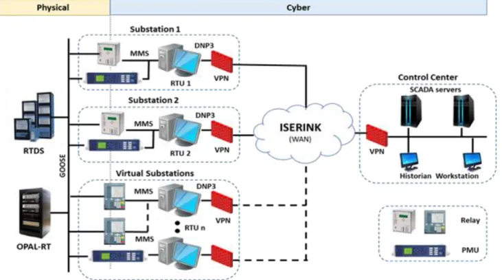
Figure 2.1 shows the current architecture of the PowerCyber CPS Security testbed at ISU. The testbed consists of SCADA hardware/software with emulation and simulation techniques that include substation automation system (SICAM PAS), control center software (Power TG), SCADA and substation communication protocols (DNP3, IEC 61850, IEEE C37.118), and security technologies (Scalance: Firewall, VPN), four multifunction protection relays (7SJ610, 7SJ82), three SEL 421 Phasor Measurement Units (PMU) and a Phasor Data Concentrator (PDC) to provide an accurate electric grid cyber infrastructure. The testbed employs virtualization technologies to address scalability concerns and reduce development cost. The testbed has also been integrated with the Internet Scale Event and Attack Generation Environment (ISEAGE) project at Iowa State to provide wide-area network emulation and advanced attack simulation. Power simulations are performed using Real Time Digital Simulator (RTDS), Opal-RT for real time evaluations and DIgSILIENT PowerFactory software for non-real time analysis [9].
2.1.2 PowerCyber Supported Use Cases
PowerCyber has been leveraged to support the following types of use cases that are relevant to cyber physical security experimentation for the grid.
2.1.2.1 Vulnerability Assessment
PowerCyber supports vulnerability assessment of industry grade SCADA software and hardware platforms, network protocols and configurations to detect unknown vulnerabilities based on standard vulnerability databases. Several unknown vulnerabilities were discovered and a responsible disclosure process was followed to disclose them to vendors and appropriate regulatory authorities [10].
2.1.2.2 Impact Analysis and Mitigation Research
PowerCyber provides a realistic virtual critical infrastructure environment wherein realistic experiments on wide-area monitoring, protection, and control in the smart grid environment can be carried out. Specifically, the testbed has been used to evaluate coordinated attacks on Remedial Action Schemes [9], and data integrity attacks on automatic generation control [11]. Also, the testbed allows the implementation of defense measures such as firewalls, intrusion detection systems, software patches, etc., to also evaluate the performance of various mitigation strategies. 2.1.2.3 Testbed Federation
Recently, the PowerCyber testbed was successfully federated with the DETER testbed and the ISERINK platform, as part of Smart America Challenge and NIST Global City Teams Challenge to create a large-scale, high-fidelity CPS security testbed environment. The federated testbed was used to demonstrate proof-of-concept attack/defense experimentation on a wide-area protection scheme [12, 13]. Additional use cases to showcase the utility of CPS testbed federation are currently being explored.
2.1.2.4 Attack-Defense Exercises & Operator training
The PowerCyber testbed and the ISERINK platform for cyber defense competitions [14] had been recently integrated to conduct realistic cyber-attack/defense training exercises for utility practitioners at the NERC GridSecCon 2015 conference [15]. Also, PowerCyber has been used every year as part of an industry workshop to provide hands-on training sessions.
2.1.2.5 Model Development
PowerCyber testbed is currently developing a repository of standardized models and experimental datasets for power systems and associated cyber systems to facilitate researchers in leveraging the testbed capabilities for cyber security experimentation.
2.1.2.6 Remote Access
In order to engage and enable a broad user community to perform a variety of power grid related cyber security experimentation, a remote access framework has been developed on the PowerCyber testbed.
2.2 Remote Access Framework
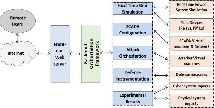
The remote access framework interacts with the remote users via a Front-end Web server, which provides a web-based user interface that allows users to configure the relevant parameters needed for the automated attack/defense experimentation. The front-end web server is integrated tightly to a backend orchestration framework, which is written in Python. The backend framework orchestrates the creation/configuration of the necessary cyber resources such as the SCADA virtual machines, manages the interaction with the power system simulators and physical devices such as the relays and PMUs, coordinates various attack actions and defense measures depending on the user input, and also provides a way for the users to collect relevant simulation artifacts from the cyber system and the physical system in the form of log files, packet captures, plots, etc., Figure 2.2 shows the overall framework for enabling remote CPS security experimentation.
The Real-Time Grid Simulation module performs actions such as model compilation, loading, and execution on a real-time power system simulator and appropriately maps components such as relays and PMUs on the power system model based on user selection. The SCADA configuration module spawns SCADA virtual machines such as the control center VM's that house the Energy Management Systems (EMS) software, substation RTU VM's, and connects these VM's according to user specified communication topology. The module also appropriately initializes SCADA communications between the various devices and verifies communications between the SCADA VM's and the hardware devices that are mapped into the experiment. Based on the user's selection,
the attack orchestration module coordinates and triggers attack actions on appropriate SCADA components. The attack module spawns attacker virtual machines once all the initializations have been performed appropriately. The attack script includes user selected attack actions from the attack template library.
Figure 2.2 Remote Access Framework
The defense instrumentation module implements host based or network based mitigation mechanisms such as firewall rules, and intrusion/anomaly detection systems appropriately based on user input. Depending on the experimental scenario chosen by the user, appropriate inputs are obtained for the scenario with respect to the power system model, hardware device mapping, communication network topologies, attack parameters and defense parameters. This allows the users to run their own experiments within the limitations of the template experimental scenarios that are provided as initial inputs. As the capabilities of the remote access framework mature, more flexibility would be available to the users to select their own experimental scenarios by using custom power system models, relay/ PMU configurations, attack vectors, and defense mechanisms
such as anomaly/intrusion detection algorithms. The following sections present a detailed description of the implementation methodology of the remote access framework.
2.2.1 Implementation Architecture
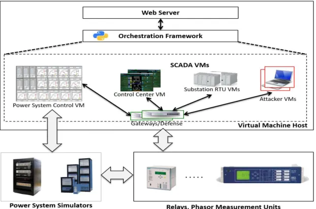
Figure 2.3 shows the implementation architecture of the PowerCyber remote access framework that was described earlier. The architecture describes remotely accessible PowerCyber testbed that consists of several interconnected VM's (SCADA, power system control, attack, defense, gateway), power system simulators, and physical devices such as relays and PMU's for performing hardware-in-the-loop experimentation.
The implementation architecture of the remote access CPS security testbed consists of three fundamental building blocks.
2.2.1.1 Front-end Web Server
The front-end web server interacts with the user through a web-based user interface. It provides options to select and customize experimental scenarios and also provides options to collect experimental results.
2.2.1.2 Backend Orchestration Framework
The back-end orchestration framework performs various tasks to automate the experimental scenario chosen, and interacts with the front-end web server to collect inputs and provide experimental results.
2.2.1.3 Models and Libraries
In order to provide standard experimental scenarios as part of the remote access web interface a library of commonly used power system models need to be developed. This includes models with appropriate WAMPAC applications modeled, commonly used attack vectors, defense measures, etc.,
The front-end web server and backend orchestration framework are hosted inside a virtual machine host, and would spawn the various virtual machines that are required as part of the experiment in the ESXi server. The front-end web server pushes user inputs as parameters to the backend orchestration framework, which is scripted using Python. The master backend script triggers multiple slave scripts which perform different functions along different stages in the design flow of the remote experimentation. The SCADA configuration script spawns control center VM and substation VM's depending on the experiment. The SCADA VM's are configured in a user specified network topology using virtual switches and gateways. Also, the backend scripts ensure that the virtual machines communicate with physical relays and PMU's that would be mapped into the experiment through the appropriate power system model. The power system
simulation automation script spawns a power system control node VM, which interacts with the Power System Simulators such as OPAL-RT, RTDS. This script provides the capability to compile/load a power system model on the simulator and allows interaction with the model to perform run-time control actions either through script or GUI and also view real-time power system impacts or obtain results in the form of data files or plots respectively. The defense script configures network based defense measures such as firewall rules or intrusion detection system rules on the virtual gateway, and/or host based defense measures on user specified components in the SCADA VM's. The attack script spawns attacker virtual machines, which would be triggered by the master script once all the initializations have been performed appropriately. The attack script includes user selected attack actions from the attack template library. Once the experiments are performed, the master script can pull cyber system artifacts such as firewall and intrusion detection log files, network packet captures, network performance statistics, etc., from the various SCADA VM's and the gateway/defense nodes. Also, as mentioned previously, the master script interacts with the power system control scripts to pull relevant physical system simulation artifacts.
2.2.2 Design Flow
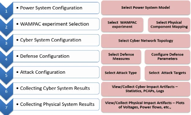
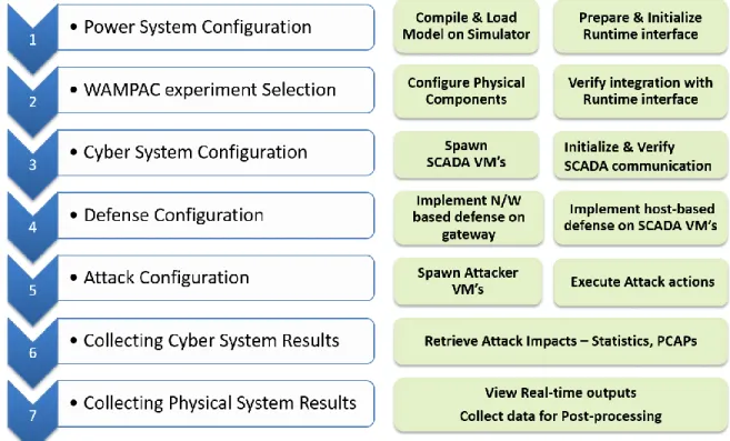
The following list represents key steps in the overall design flow for performing automated, cyber-attack/defense experimentation:
Power system configuration
The first stage involves the selection of the power system model to be used for the experiment. For example, the standard IEEE system models such as 39 bus, 118 bus, etc.,
WAMPAC experiment selection
Once the power system model has been selected, the next stage is to identify the Wide-Area Monitoring, Protection and Control (WAMPAC) experiment that is to be used for the experiment.
This stage would also involve an identification of how the physical components are mapped to the power system model.
Cyber system configuration
This stage involves actions to appropriately spawn SCADA VM's such as Control Center, Substation VM's depending on the WAMPAC experimental scenario chosen, and ensuring that the appropriate network topology is setup between the various VM's and the hardware devices that are mapped as part of the scenario.
Defense configuration
After the power system and cyber system configuration steps are performed, the next stage involves actions to spawn defense measures. The defense measures could be setup either in the communication gateway nodes or on the individual hosts depending on the experimental scenarios and user inputs.
Attack Configuration
Once all the systems are configured and initialized, the next stage is to spawn the attacker VM's and execute the attack vector on specified targets in coordination with the backend orchestration framework.
Collecting Cyber System Results
After the execution of the specified attack scenario, the next stage involves the collection of experimental artifacts on the cyber layer such as log files, packet captures, network performance metrics from the various systems.
Collecting Physical System Results
The last stage involves the collection of power system simulation artifacts in the form of datasets, or plots of system states such as voltages, power ow and frequency.
The following subsections describe in detail the various activities that are performed as part of the overall design flow with respect to user interface (front-end) and experiment automation (back-end).
2.2.2.1 User Interface Design
The user interface provides the user with an array of templates to select from and configure the system to perform a specific type of cyber-attack/ defense experiment. Figure 2.4 shows the various activities with respect to the design flow for remote experimentation pertaining to the user interface. The user interface allows the user to select the power system model that is to be used from a list of choices such as IEEE 39 bus model IEEE 118 bus model, etc., As part of Step 2, the user can select the WAMPAC experimental scenarios to be used. For example, the list of available scenarios could be Remedial Action Schemes, Automatic Generation Control, State Estimation, etc.,
Each one of these WAMPAC applications correspond to a specific scenario and based on the user input they will be presented with subsequent web pages to select and map physical components such as relays and PMUs appropriately into their experiment, and also it determines the type and number of SCADA VM's needed. For the cyber system configuration, the user interface provides user with options to select the network topology in which SCADA components should be connected.
As part of defense measures, the user can select from either host based defense or network based defense. Based on their inputs, user interface provides options to select from defense methodologies such as firewall, intrusion detection and prevention based defense, etc., for implementation. For orchestrating the attack, the user interface provides a list of attack vectors such as DOS attack, Command injection attack, coordinated attack to choose from, along with options to choose the attack locations on the system selected. The user interface has a visualization component where remote users can observe the status of the physical devices that are part of the attack on the cyber layer, and also simultaneously observe the power system impacts on the real-time power system simulator through real-real-time simulation plots. Once the experiment has been performed, the user interface facilitates the collection of cyber system impacts such as downloading packet captures, log files etc., during attack phase. As part of power system impacts, the user interface provides the option of data collection relevant to power
system parameters such as voltage and power flow plots. 2.2.2.2 Experiment Automation
Figure 2.5 lists the various activities as part of the design flow that relate to experiment automation. Each of the activities are implemented using the backend orchestration framework through appropriate slave scripts that communicate to a master script. With respect to the power
system configuration, the automation tasks involve loading, compilation of the appropriate power system model such as the IEEE 9 bus system model simulator, initializing the runtime interface, and ensuring that the model has reached its steady state operating condition before any attack actions are started.
Figure 2.5 Design Flow for Experiment Automation
Depending on the WAMPAC experiment selection made, the backend automation scripts would configure physical components accordingly so that they could be mapped into the power system model for hardware-in-the-loop experiments, and also verify their integration with the runtime interface. With respect to automating the cyber system, the back-end configuration module spawns control center and substation VM's appropriately, and initializes the VM's in a specific network topology. Also, the scripts verify if inter-device communication is successful before proceeding further. Based on user selection, the backend scripts implement and initialize network
based or host based defense measures such as firewalls, or intrusion detection systems on gateway nodes or on the hosts such as substation VM's. As part of attack orchestration, the backend scripts
would spawn attacker VM's, which have a library of pre-defined attack modules. Based on the
experiment scenario, the master script coordinates and triggers the specific attack scripts on these VM's.
Once the experiment has successfully begun, the backend scripts periodically poll the status of various devices involved in the experiment in the cyber layer, and update a run-time visualization screen on the front-end web server. Simultaneously, the web-based interface can also provide another screen with the run-time interface on the power system control VM to see the impact of the attacks on the power system. Depending on the type of power system simulator selected and the type of outputs requested by the user (i.e. real-time outputs vs. offline plots), the automation scripts would be adapted to provide real-time outputs or data files that are collected for the experimental scenario accordingly. As part of collecting the results on the cyber layer, the back-end scripts would pull log files from the VM's where defense measures were deployed such as firewall and IDS logs, and packet captures from the gateway node, besides other network performance statistics. Similarly, the scripts on the power system control node would pull power system simulation artifacts such as data files or plots and make them available to the user as experimental results.
CHAPTER 3
STORY-BOARDS & CASESTUDY
3.1 Story-Board Constructs
The PowerCyber remote access framework has been implemented using story board based approach. This implementation facilitates ease of use for a versatile community of users with different expertise and also serves as an educational platform that allows users to learn about the importance and criticality of cyber security of critical infrastructures such as smart grid. The remote access framework supports the following story board constructs [32].
3.1.1 Story-Board 1 - Cascading outage through a coordinated attack on power system protection scheme
In this scenario, the attack involves a combination of two coordinated attack actions on a power system protection scheme known as Remedial Action Scheme (RAS). Typically, RAS are intended to take specific protective measures to prevent the spread of large disturbances under heavy system loading conditions. However, the attacker intelligently triggers the operation of this RAS by creating a data integrity attack on unencrypted communication between the substation and the control center that uses the DNP3 protocol. In order to create a cascading outage, the attacker also blocks the communication between the protection relays that are involved in the RAS through a targeted Denial of Service (DoS) attack on one of the protection controllers. This prevents the successful operation of the RAS and in turn initiates secondary protection to be tripped to avoid thermal overload on the impacted transmission line. As a result of this coordinated attack involving data integrity attack to trip a breaker and a DoS attack on RAS communications, the overall system frequency is also affected as it causes the islanding of a generator from the rest of the system.
3.1.2 Story-Board 2 - Manipulating AGC measurements/controls to affect system frequency In this scenario, the attack involves a stealthy manipulation of measurements/controls used in Automatic Generation Control (AGC) algorithm to destabilize and affect the frequency of the power grid. This attack is a version of the classic Man-in-the-Middle attack, where the attacker intercepts the communication between the control center and the remote substations and chooses to stealthily modify either the frequency or tie-line measurements going to the control center, or the AGC control commands going to the generating stations. This is achieved by executing an ARP poisoning attack first, which tricks the remote substation to forward the data to the attacker before sending it to the external gateway. The attacker then selects the appropriate information that is to be replaced and modifies it appropriately using custom attack scripts and forwards it to the external gateway. As a result of this manipulation, there is a steady frequency deviation in the system. Eventually, this frequency deviation causes the load in the system to be shed in an attempt to restore frequency. A sustained attack could potentially lead to a major portion of the load in the power system to be unserved.
3.1.3 Story-Board 3 - Manipulating SCADA measurements to affect situational awareness in State Estimator
In this scenario, the attack involves a careful manipulation of the measurements (analog and status) that come from the substation remote terminal units (RTU) to the control center for State Estimation. The attacker performs a stealthy attack where he exploits his knowledge about the measurement configurations at multiple substations to carefully select the locations where he would manipulate the measurements. The attack vector involves the classic Man-in-the-Middle attack, where the attacker tricks the RTU to forward all its data to the attacker’s machine instead of the substation gateway using an ARP poisoning attack. By decoding the unencrypted network
traffic, the attacker selects and modifies appropriately certain targeted measurements to avoid detection by the State Estimator’s Bad Data Detectors. This does not cause any bad data alarms in the control center and consequently, the attacker succeeds in impeding the situational awareness capabilities of the operator. Consequently, all applications that rely on State Estimator would be affected such as Contingency Analysis, Power Markets, etc., Also, this attack could be used to further trigger other attacks that could cause additional damage such as opening/overloading critical transmission lines.
3.1.4 Story-Board 4 - Using unencrypted RTU communication to send arbitrary commands to trip breakers
The attacker gains physical access to the process WAN, on which he is able to gain a network address. As the data flows between RTUs and SCADA are not encrypted the attacker is able to read any transmitted data in clear text. The attacker uses this opportunity to perform an ARP spoof attack and position himself between an RTU and the PCU (i.e., a man-in-the-middle attack). As such, the attacker is able to both send malicious requests to the RTU and hide to the operator the real events. The attacker uses this for an unauthorized opening of a distribution feeder breaker feeding a major manufacturing industry connected directly on the 40 kv level. The attacker’s intention is to create a power outage that will severely disturb or stop the production in a continuously operated plant in order to create economical and/or physical damage.
3.1.5 Story-Board 5 - Denial of Service attack on RTU/protection devices communication to blind SCADA
The attacker has physical access to the RTU communication network and is as such able to connect his own equipment to the network using a switch in an unmanned substation. From this point the attacker floods a number of logical connections with a continuous stream of packets,
which creates an overload in the Front-End applications and blinds the operators to what is happening in the grid. The attacker has chosen a time for the attack when a severe snow and ice storm is expected and the control operators are unable to counteract the loss of physical devices created by the storm. This leads to an overload of power lines feeding the capital city and this also goes unnoticed in the control center. The blind SCADA severely delays the power restoration efforts to reenergize the capital city.
3.1.6 Story-Board 6 - Exploiting Social Engineering to gain access to Energy Management Systems/ Substation Workstations
An uninformed operator in the control room connects his workstation to Internet during a night shift. He does this to be able to use Facebook to chat with his friends and to surf on Internet. This operator has the tendency to accept any friend request on Facebook and add as his friend. The attacker uses this to request the operator to add him as a friend. In a chat, his Facebook friend sends him a link that was created by an attacker. Without becoming suspicious, the operator clicks on the link and gives the attacker access to his control room workstation. The attacker is now able to remotely connect to this system and he can open a shell with root privileges on the compromised system. From his own location the attacker is now able to open SCADA displays containing real-time information from the grid and to execute commands. He uses this to open HV breakers in the power grid, which leads to cascading events that causes a total blackout of the high voltage grid.
3.1.7 Story-Board 7 - Manipulating protection settings using Substation Automation tools The attacker is an employee of the attacked utility and he has access to substations and to substation engineering tools. He uses the engineering tools for the substation protection devices to set line protection parameters to default values. The default values in the protection devices are
defined at such low limits that the protection devices will trip all power lines also at a normal operating state. The attack is done in a central HV/MV substation on the MV side and it will cause a total blackout in the capital city.
3.2 Case Study
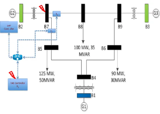
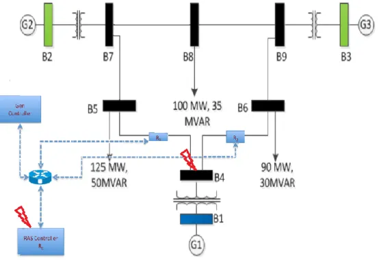
This section describes how the remote access CPS security testbed was used to perform a coordinated attack/defense experiment on a wide-area protection scheme. The experimental scenario involves a coordinated cyber-attack on a Remedial Action Scheme (RAS), which is a commonly used Wide-Area Protection scheme, as specified in [9]. Once the remote users login by providing their credentials, the user interface collects various information. For this case study, the IEEE 9-bus power system model was chosen, and RAS scheme was chosen as the WAMPAC experimental scenario. The web interface presents a set of options for mapping the RAS onto the generators in the 9 bus system model. As part of the back-end orchestration framework, the power system control VM is spawned and the runtime interface of the real-time power system simulator is triggered. The IEEE 9-bus model with RAS is then initialized on the run-time interface of the real-time power system simulator. The back-end framework triggers the SCADA configuration module, which spawns SCADA VM’s corresponding to power system simulation and checks network connectivity between devices. Upon successfully spawning the SCADA VM's, the user is provided with options to perform reconnaissance and enumeration followed by list of attack options such as gaining foothold in the internal SCADA network, data integrity attack, DoS attack etc., In this case study, a coordinated attack is chosen. The first part of the coordinated attack involves a data integrity attack by executing a malicious command injection to the substation RTU at bus 7 to trip one of the physical relays involved in the RAS. The second element in the
coordinated attack involves a DoS attack on the RAS controller, which is another physical relay to block communication between the RAS controller and the generator controller. The users can select whether a defense measure is to be implemented as part of the experimental scenario. For this experimental scenario, the possible defense measures include a firewall rule at the substation gateway node to whitelist communication into the substation and updating security patches. This prevents the data integrity attack from succeeding and also prevents attacker infiltration into the internal SCADA network. Also, the users can select to implement throttling of the network traffic on the substation gateway to ensure that the impact of the DoS attack is minimized. The cyber layer visualization system constantly updates the status of the physical relays on the experiment to show the attack impacts. In addition to the visualization, as a part of post-attack data collection, the framework allows users to download capture of communication packets between all devices (cyber & physical). These packet captures can be used to analyze and understand the communication flow in the system before and after attack implementation which might be useful in design of anomaly detection algorithms. The power system run-time interface provides the users with real-time power system outputs as the attack is being executed. Also, it provides the users to interact with the power system model by applying manual control actions directly through the GUI. The framework provides two options for analyzing the power system impacts: real-time outputs for the users to observe vs. data files that could be processed offline. For this case study, only the real-time outputs option has been shown. As an additional feature, the framework will provide an option in the future to collect data files corresponding to appropriate power system parameters in the system model such as voltages, power flows and system frequency.
The reminder of this section captures the sample case study with step-by-step explanations and corresponding screen shots.
Step 1: To gain access to remote access framework, the users connect to PowerCyber laboratory virtual private network (VPN). This is done by downloading VPN clients such as OpenVPN, Viscosity or Tunnelblick and providing certificates and credentials for VPN access. Upon successful connection to VPN, the remote users connect to PowerCyber remote access framework URL and provide credentials to log into the framework.
Step 2: Upon succesfull login, the interface provides story board scenarios for the remote users to choose from. A detailed description of story board scenario selected is displayed to the user. The screenshot below captures the description of Story Board 1: Cascading outage through a coordinated attack on power system protection scheme.
3
Step 3: The next webpage provides an overview video snippet of the scenario described in Story Board 1 [12]. The video demonstarates the impact of coordinated attack (data integrity and denial of service) on IEEE 9-bus system distributed across the state of IOWA. The video uses OPC server interfacing with SICAM and Google earth interface for visualizing the scenario decribed.
Step 4: The next webpage is the home page which is categorized into four main modules: Real-Time Grid Simulation, SCADA Configuration, Attack Orchestration and Defense Instrumentation. These four modules are the fundamental building blocks for orchestrating attack/defense experimentation in PowerCybed testbed environment.
Step 5: The real-time grid simulation module involves selection of IEEE Bus Model (such as 9-bus, 39-bus, etc.) from a drop down menu followed by selection of WAMPAC(Wide-Area Monitoring, Protection and Control) systems. The framework provides three WAMPAC types for selection, namely: Remedial Action Scheme (Wide-Area Protection scheme), Automatic Generation Control (Wide-Area Control scheme) and State Estimation (Wide-Area Monitoring scheme).
Step 6: For enhancing user programmability, second step in real-time grid simulation module involves identification of how the physical components should be mapped to the power system model. In particular, this case study identifies three possible positions for placing Remedial Action Scheme on IEEE 9-bus system, namely: Remedial Action Scheme for Generator 2, Remedial Action Scheme for Generator 1 and Remedial Action Scheme for Generator 3.
Step 7: The model selected by remote user is compiled, loaded and executed on the real-time power system simulator and the run time visualization environment is provided to the user. The environment provides meters representing generation levels, overall system frequency, tie-line flows of transmission lines, bus voltages and loads to clearly capture the state of power system model before and after cyber-attack, defense simulation.
Step 8: The SCADA configuration module is responsible for spawning SCADA virtual machines and communication topology on the DELL PowerEdge ESXi server at PowerCyber Lab.
Specifically, the topology spawned for story board 1 consists of three networks: SCADA Control network, SCADA Substation Network and Wide Area Network (WAN). Virtual switches(vSwitch) were spawned in ESXi server (one each for each network) to create network topologies required for experimentation.
1. SCADA Control network (10.1.1.0/24) – consists of Primary control center (10.1.1.10/24), Secondary control center (10.1.1.20/24), and Control gateway (10.1.1.1/24).
2. SCADA Substation network (10.2.2.0/24) – consists of Substation simulator (10.2.2.10/24) and Substation gateway (10.2.2.1/24). The Substation simulator is in turn connected to the physical Siemens and Schweitzer relays in PowerCyber testbed environment.
3. Wide Area Network (WAN) (192.168.16.0/24) - connects the Control gateway (192.168.16.160/24) and Substation gateway (192.168.16.150/24) using a site-to-site OPEN VPN tunnel which encrypts two-way SCADA communication between control centers and substation. The Attacker virtual machine (192.168.16.140/24) running Kali Linux operating system is also connected to the Wide Area Network for providing the remote user with capabilities to perform penetration testing in PowerCyber testbed SCADA environment.
Step 9: The Attack orchestration module involves two steps: 1. Reconnaissance and Enumeration 2. Vulnerability Exploitation. Each of these steps are subdivided into four steps respectively. During reconnaissance phase, interesting information about the target is collected which is used during enumeration phase to identify possible entry points into the internal network. In vulnerability exploitation phase, the identified security weaknesses are exploited to gain access into the internal SCADA communication network which results in manifestation of SCADA virtual machines causing physical impacts on power system models.
Step 9.1: During host discovery, the attacker tries identifying internet facing hosts on the target 192.168.16.0/24 network using nmap command which performs ping sweep and prints out available hosts that responded to host discovery probes. In this scenario, 192.168.16.160 (Control gateway) and 192.168.16.150(Substation gateway) are identified as being live.
Step 9.2: In network sniffing phase, the attacker captures all traffic between the discovered hosts 192.168.16.160 and 192.168.16.150. Due to the presence of site-to-site VPN tunnel between the Control gateway and Substation gateway, the Attacker is unsuccessful in decrypting the contents of packets exchanged between the Control Center and Substation. The attacker now tries identifying backdoor techniques to penetrate into the internal network.
Step 9.3: The attacker next performs intense port scanning to identify top ten TCP ports which are open on the target hosts using nmap commands. In this scenario, TCP port running SSH service and TCP port running HTTPS are identified by the attacker as being open on the target hosts.
Step 9.4: Vulnerability scanning identifies that the Substation gateway is vulnerable to Heartbleed bug which is a serious vulnerability in OpenSSL cryptographic software library that allows the attacker to steal information protected by the SSL/TLS encryption used to secure the internet.
Step 9.5: In vulnerability exploitation phase initially, the remote attacker exploits Heartbleed vulnerability which allows the attacker to obtain up to 64 KB of unencrypted sensitive data from the memory of a vulnerable OpenSSL server. In this scenario the credentials (username and password) of the Substation gateway vulnerable to Heartbleed is extracted by the attacker using packets that trigger a buffer over-read.
Step 9.6: The attacker makes use of credentials obtained using Heartbleed vulnerability to gain SSH access into the substation gateway. This in turn allows the attacker to obtain root access with administrator privilege and capture two-way SCADA communication traffic between control center and substation. This step serves as the stepping stone for performing a successful coordinated attack on the power system model.