332
VB (Serial Comms)
26.1 Introduction
This chapter discusses how Visual Basic can be used to access serial communication functions. Windows hides much of the complexity of serial communications and auto-matically puts any received characters in a receive buffer and characters sent into a transmission buffer. The receive buffer can be read by the program whenever it has time and the transmit buffer is emptied when it is free to send characters.
26.2 Communications control
Visual Basic allows many additional components to be added to the toolbox. The Micro-soft Comm component is used to add a serial communication facility.
This is added to the toolbox with: Project→Components (Ctrl-T) or in Visual Basic 4 with: Tools→Custom Controls (Ctrl-T)
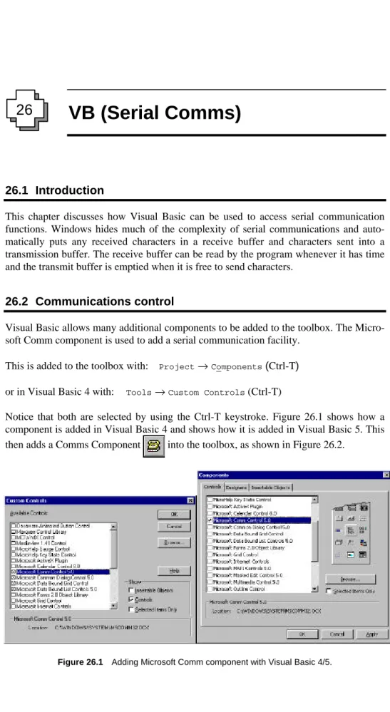
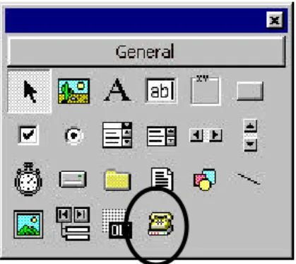
Notice that both are selected by using the Ctrl-T keystroke. Figure 26.1 shows how a component is added in Visual Basic 4 and shows how it is added in Visual Basic 5. This then adds a Comms Component into the toolbox, as shown in Figure 26.2.
Figure 26.1 Adding Microsoft Comm component with Visual Basic 4/5.
Figure 26.2 Toolbox showing Comms components.
In order to use the Comms component the files MSCOMM16.OCX (for a 16-bit module) or MSCOMM32.OCX (for a 32-bit module) must be present in the \WINDOWS\SYSTEM directory. The class name is MSComm.
The communications control provides the following two ways for handling commu-nications:
• Event-driven. Event-driven communications is the best method of handling serial communication as it frees the computer to do other things. The event can be defined as the reception of a character, a change in CD (carrier detect) or a change in RTS (request to send). The OnComm event can be used to capture these events. and also to detect communications errors.
• Polling. CommEvent properties can be tested to determine if an event or an error has occurred. For example, the program can loop waiting for a character to be received. Once it is the character is read from the receive buffer. This method is normally used when the program has time to poll the communications receiver or that a known re-sponse is imminent.
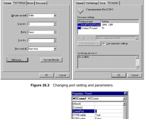
Visual Basic uses the standard Windows drivers for the serial communication ports (such as serialui.dll and serial.vxd). The communication control is added to the application for each port. The parameters (such as the bit rate, parity, and so on) can be changed by se-lecting Control Panel → System → Device Manager → Ports (COM and LPT) → Port Settings. The settings of the communications port (the IRQ and the port address) can be changed by selecting Control Panel → System → Device Manager → Ports (COM and LPT) → Resources for IRQ and Addresses. Figure 26.3 shows example parameters and settings.
26.3 Properties
The Comm component is added to a form whenever serial communications are required (as shown in left-hand side of Figure 26.4). The right-hand side of Figure 26.5 shows its properties. By default, the first created object is named MSComm1 (the second is named MSComm2, and so on). It can be seen that the main properties of the object are: CommPort, DTREnable, EOFEnable, Handshaking, InBufferSize, Index, InputLen, In-putMode, Left, Name, NullDiscard, OutBufferSize, ParityReplace, RThreshold, RTSEnable, Settings, SThreshold, Tag and Top. The main properties are defined in Ta-ble 26.1.
Figure 26.3 Changing port setting and parameters.
Figure 26.4 Communications control and MS Comm Properties. Table 26.1 The main communications control properties.
Properties Description
CommPort Sets and returns the communications port number. Input Returns and removes characters from the receive buffer. Output Writes a string of characters to the transmit buffer. PortOpen Opens and closes a port, and gets port settings
Settings Sets and returns port parameters, such as bit rate, parity, number of data bits and so on.
26.3.1Settings
The Settings property sets and returns the RS-232 parameters, such as baud rate, parity, the number of data bit, and the number of stop bits. Its syntax is:
[form.]MSComm.Settings[ = setStr$]
where the strStr is a string which contains the RS-232 settings. This string takes the form:
"BBBB,P,D,S"
where BBBB defines the baud rate, P the parity, D the number of data bits, and S the num-ber of stop bits.
The following lists the valid baud rates (default is 9600 Baud):
110, 300, 600, 1200, 2400, 9600, 14 400, 19 200, 38 400, 56 000, 128 000, 256 000. The valid parity values are (default is N): E (Even), M (Mark), N (None), O (Odd), S (Space).
The valid data bit values are (default is 8): 4, 5, 6, 7 or 8. The valid stop bit values are (default is 1). 1, 1.5 or 2.
An example of setting a control port to 4800 Baud, even parity, 7 data bits and 1 stop bit is:
Com1.Settings = "4800,E,7,1"
26.3.2CommPort
The CommPort property sets and returns the communication port number. Its syntax is: [form.]MSComm.CommPort[ = portNumber%]
which defines the portNumber from a value between 1 and 99. A value of 68 is returned if the port does not exist.
26.3.3PortOpen
The PortOpen property sets and returns the state of the communications port. Its syntax is:
[form.]MSComm.PortOpen[ = {True | False}]
A True setting opens the port, while a False closes the port and clears the receive and transmit buffers (this automatically happens when an application is closed).
The following example opens communications port number 1 (COM1:) at 4800 Baud with even parity, 7 data bits and 1 stop bit:
Com1.Settings = "4800,E,7,1" Com1.CommPort = 1
Com1.PortOpen = True
26.3.4Inputting data
The three main properties used to read data from the receive buffer are Input, InBuffer-Count and InBufferSize.
Input
The Input property returns and removes a string of characters from the receive buffer. Its syntax is:
[form.]MSComm.Input
To determine the number of characters in the buffer the InBufferCount property is tested (to be covered in the next section). Setting InputLen to 0 causes the Input property to read the entire contents of the receive buffer.
Program 26.1 shows an example of how to read data from the receiver buffer.
&
Program 26.1
' Check for characters in the buffer If Com1.InBufferCount Then
' Read data in the buffer InStr$ = Com1.Input End If
InBufferSize
The InBufferSize property sets and returns the maximum number of characters that can be received in the receive buffer (by default it is 1024 bytes). Its syntax is:
[form.]MSComm.InBufferSize[ = numBytes%]
The size of the buffer should be set so that it can store the maximum number of charac-ters that will be received before the application program can read them from the buffer.
InBufferCount
The InBufferCount property returns the number of characters in the receive buffer. It can also be used to clear the buffer by setting the number of characters to 0. Its syntax is: [form.]MSComm.InBufferCount[ = count%]
26.3.5Outputting data
The three main properties used to write data to the transmit buffer are Output, OutBuf-ferCount and OutBufferSize.
Output
[form.]MSComm.Output[ = outString$]
Program 26.2 uses the KeyPress event on a form to send the character to the serial port.
&
Program 26.2
Private Sub Form_KeyPress (KeyAscii As Integer) if (Com1.OutBufferCount < Com1.OutBufferSize) Com1.Output = Chr$(KeyAscii)
End Sub
OutBufferSize
The OutBufferSize property sets and returns the number of characters in the transmit buffer (default size is 512 characters). Its syntax is:
[form.]MSComm.OutBufferSize[ = NumBytes%]
OutBufferCount
The OutBufferCount property returns the number of characters in the transmit buffer. The transmit buffer can also be cleared by setting it to 0. Its syntax is:
[form.]MSComm.OutBufferCount[ = 0] 26.3.6Other properties
Other properties are:
• Break. Sets or clears the break signal. A True sets the break signal, while a False clears the break signal. When True character transmission is suspended and a break level is set on the line. This continues until Break is set to False. Its syntax is: [form.]MSComm.Break[ = {True | False}]
• CDTimeout. Sets and returns the maximum amount of time that the control waits for a carried detect (CD) signal, in milliseconds, before a timeout. Its syntax is: [form.]MSComm.CDTimeout[ = milliseconds&]
• CTSHolding. Determines whether the CTS line should be detected. CTS is typically used for hardware handshaking. Its syntax is:
[form.]MSComm.CTSHolding[ = {True | False}]
• DSRHolding. Determines the DSR line state. DSR is typically used to indicate the presence of a modem. If is a True then the DSR line is high, else it is low. Its syntax is:
[form.]MSComm.DSRHolding[ = setting]
• DSRTimeout. Sets and returns the number of milliseconds to wait for the DSR sig-nal before an OnComm event occurs. Its syntax is:
[form.]MSComm.DSRTimeout[ = milliseconds&]
• DTEEnable. Determines whether the DTR signal is enabled. It is typically send from the computer to the modem to indicate that it is ready to receive data. A True setting enables the DTR line (output level high). It syntax is:
[form.]MSComm.DTREnable[ = {True | False}]
• RTSEnable. Determines whether the RTS signal is enabled. Normally used to hand-shake incoming data and is controlled by the computer. Its syntax is:
[form.]MSComm.RTSEnable[ = {True | False}]
• NullDiscard. Determines whether null characters are read into the receive buffer. A True setting does not transfer the characters. Its syntax is:
[form.]MSComm.NullDiscard[ = {True | False}]
• SThreshold. Sets and returns the minimum number of characters allowable in the transmit buffer before the OnComm event. A 0 value disables generating the On-Comm event for all transmission events, while a value of 1 causes the OnOn-Comm event to be called when the transmit buffer is empty. Its syntax is:
[form.]MSComm.SThreshold[ = numChars%]
• Handshaking. Sets and returns the handshaking protocol. It can be set to no hand-shaking, hardware handshaking (using RTS/CTS) or software handshaking (XON/XOFF). Valid settings are given in Table 26.2. Its syntax is:
[form.]MSComm.Handshaking[ = protocol%]
• CommEvent. Returns the most recent error message. Its syntax is: [form.]MSComm.CommEvent
Table 26.2 Settings for handshaking.
Setting Value Description
comNone 0 No handshaking (Default). comXOnXOff 1 XON/XOFF handshaking.
comRTS 2 RTS/CTS handshaking.
comRTSXOnXOff 3 RTS/CTS and XON/XOFF handshaking.
When a serial communication event (OnComm) occurs then the event (error or change) can be determined by testing the CommEvent property. Table 26.3 lists the error values and Table 26.4 lists the communications events.
Table 26.3 CommEvent property.
Setting Value Description
comBreak 1001 Break signal received.
comCTSTO 1002 CTSTimeout. Occurs when transmitting a character and CTS was low for CTSTimeout milliseconds.
comDSRTO 1003 DSRTimeout. Occurs when transmitting a character and DTR was low for DTRTimeout milliseconds.
comFrame 1004 Framing Error.
comOverrun 1006 Port Overrun. The receive buffer is full and another character was written into the buffer, overwriting the previously received character.
comCDTO 1007 CD Timeout. Occurs CD was low for CDTimeout milliseconds, when transmitting a character.
comRxOver 1008 Receive buffer overflow. comRxParity 1009 Parity error.
comTxFull 1010 Transmit buffer full.
Table 26.4 Communications events.
Setting Value Description
comEvSend 1 Character has been sent. comEvReceive 2 Character has been received. comEvCTS 3 Change in CTS line.
comEvDSR 4 Change in DSR line from a high to a low. comEvCD 5 Change in CD line.
comEvRing 6 Ring detected.
comEvEOF 7 EOF character received.
26.4 Events
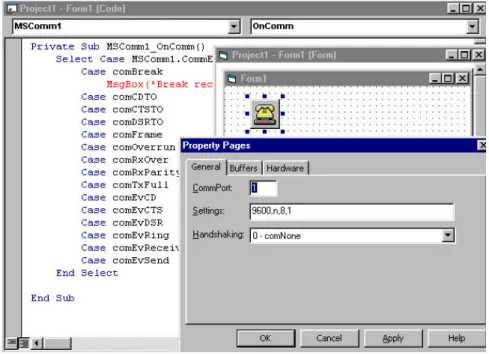
The Communication control generates an event (OnComm) when the value CommEvent property changes its value. Figure 26.5 shows the event subroutine and Program 26.3 shows an example event routine which tests the CommEvent property. It also shows the property window which is shown with a right click on the comms component.
Figure 26.5 OnComm event.
&
Program 26.3
Private Sub MSComm_OnComm () Select Case MSComm1.CommEvent
Case comBreak ' A Break was received. MsgBox(″Break received″)
Case comCDTO ' CD (RLSD) Timeout. Case comCTSTO ' CTS Timeout. Case comDSRTO ' DSR Timeout. Case comFrame ' Framing Error Case comOverrun ' Data Lost.
Case comRxOver ' Receive buffer overflow. Case comRxParity ' Parity Error.
Case comTxFull ' Transmit buffer full. Case comEvCD ' Change in the CD. Case comEvCTS ' Change in the CTS. Case comEvDSR ' Change in the DSR. Case comEvRing ' Change in the RI. Case comEvReceive
Case comEvSend End Select
End Sub
26.5 Example program
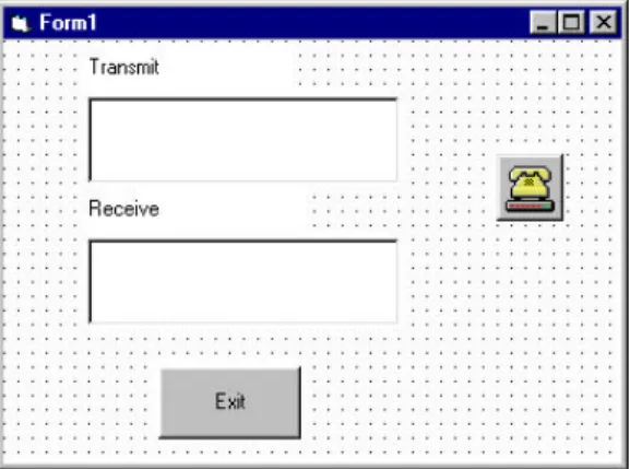
Program 26.4 shows a simple transmit/receive program which uses COM1: to transmit and receive. A loopback connection which connects the transmit line to the receive line can be used to test the communications port. All the characters that are transmitted should be automatically received. A sample form is given in Figure 26.6.
Figure 26.6 Simple serial communications transmit/receive form.
The loading of the form (Form_Load) is called when the program is initially run. This is used to set-up the communication parameters (in this case to 9600 Baud, no parity, 8 data bits and 1 stop bit). When the user presses a key on the form the Form_Keypress event is called. This is then used to transmit the entered character and display it to the Transmit text window (Text1). When a character is received the OnComm event is called and the MSComm1.CommEvent is set to 2 (comEvReceive) which identifies that a character has been received. This character is then displayed to the Receive text win-dow (Text2). Figure 26.7 shows a sample run.
&
Program 26.4
Private Sub Form_Load()
MSComm1.CommPort = 1 ' Use COM1.
MSComm1.Settings = "9600,N,8,1" ' 9600 baud, no parity, 8 data, ' and 1 stop bit.
MSComm1.InputLen = 0 ' Read entire buffer when Input ' is used
MSComm1.PortOpen = True ' Open port End Sub
Private Sub Form_KeyPress(KeyAscii As Integer) MSComm1.Output = KeyAscii
Text1.Text = KeyAscii End Sub
Private Sub MSComm1_OnComm()
If (MSComm1.CommEvent = comEvReceive) Then Text2.Text = MSComm1.Input
End If End Sub
Private Sub Command1_Click() End
Figure 26.7 Sample run.
26.6 Error messages
Table 26.5 identifies the run-time errors that can occur with the Communications con-trol.
Table 26.5 Error messages.
Error number
Message explanation Error
number
Message explanation
8000 Invalid operation on an opened port 8010 Hardware is not available 8001 Timeout value must be greater than zero 8011 Cannot allocate the queues 8002 Invalid port number 8012 Device is not open 8003 Property available only at run-time 8013 Device is already open 8004 Property is read-only at run-time 8014 Could not enable Comm
notification
8005 Port already open 8015 Could not set Comm state 8006 Device identifier is invalid 8016 Could not set Comm event
mask
8006 Device identifier is invalid 8018 Operation valid only when the port is open
8007 Unsupported Baud rate 8019 Device busy
8008 Invalid Byte size is invalid 8020 Error reading Comm device 8009 Error in default parameters
26.7 RS-232 polling
The previous program used interrupt-driven RS-232. It is also possible to use polling to communicate over RS-232. Program 26.5 uses COM2 to send the message ‘Hello’ and then waits for a received string. It determines that there has been a response by continu-ally testing the number of received characters in the receive buffer (InBufferCount). When there is more than one character in the input buffer it is read.
&
Program 26.5
Private Sub Form_Load()
Dim Str As String ' String to hold input
MSComm1.CommPort = 2 ' Use COM2
MSComm1.Settings = "9600,N,8,1" ' 9600 baud, no parity, 8 data, ' and 1 stop bit
MSComm1.InputLen = 0 ' Read entire buffer when Input ' is used
MSComm1.PortOpen = True ' Open port
Text1.Text = "Sending: Hello"
MSComm1.Output = "Hello" ' Send message
Do ' Wait for response from port DoEvents
Loop Until MSComm1.InBufferCount >= 2
Str = MSComm1.Input ' Read input buffer Text1.Text = "Received: " + Str
MSComm1.PortOpen = False ' Close serial port. End Sub
26.8 Exercises
26.8.1 List the properties of the MSComm control and outline their uses.
26.8.2 Write a Visual Basic program that continuously sends the character ‘A’ to the serial line. If possible, observe the output on an oscilloscope and identify the bit pattern and the baud rate.
26.8.3 Write a program that continuously sends the characters from ‘A’ to ‘Z’ to the serial line. If possible, observe the output on an oscilloscope.
26.8.4 Write a Visual Basic program that prompts the user for the main RS-232 pa-rameters, such as bit rate, parity, and so on. The user should then be able to transmit and receive with those parameters.
26.8.5 If possible, connect two computers together with a serial link and write a pro-gram which uses full-duplex communications.
26.8.6 If possible, connect two computers together with a serial link and write a pro-gram which uses full-duplex communications.
26.8.7 Write a program which tests some of the run-time errors given in Table 26.5.
26.8.8 Investigate the Handshaking property of the MSComm control. Its settings are:
0 - comNone 1 - comXOnXoff