Copyright © 2018 Authors. This is an open access article distributed under the Creative Commons Attribution License, which permits unrestricted use, distribution, and reproduction in any medium, provided the original work is properly cited.
International Journal of Engineering & Technology
Website: www.sciencepubco.com/index.php/IJET
Research paper
An Overview of Local Positioning System:
Technologies, Techniques and Applications
Hameedah Sahib Hasan1, Mohamed Hussein2, Shaharil Mad Saad2*and Mohd Azuwan Mat Dzahir2
1
Ministry of Higher Education and Scientific Research, Al-Furat Al-Awsat Technical University, Iraq.
2
Faculty of Mechanical Engineering, Universiti Teknologi Malaysia (UTM), Johor Bauru, 81310, Malaysia. *Corresponding author E-mail : [email protected]
Abstract
Positioning system like global position system (GPS) and Local position system (LPS) have become very important in a large number of applications such as monitoring and tracking, etc. Because of the limitations of GPS in indoor environments due to the lack of line of sight (LoS), the use of LPS has become a true necessary to estimate user‟s or object position with a good accuracy. In order to choose the best LPS system, a compromise between accuracy, precision, power consumption, coverage and cost should be taken into account. This paper introduces an overview of LPS performance parameters, current technologies, techniques and methods used by LPS. On the other hand, the comparison between LPS technologies and techniques used based on those technologies are also discussed. Furthermore, the LPS‟s applications that have been done by previous researches such as human tracking, object tracking, animal tracking and automatic guide vehicle (AGV) tracking will be discussed. We believe this paper would catalyze further investigation by the researcher which is interested on the LPS field.
Keywords: Local Positioning System; Global Position System; LPS Techniques and Application; Tracking; Automated Guide Vehicle
1.
Introduction
As new technologies develop at a great pace, local position system (LPS) become more and more diversified and increasingly im-portant in a large number of applications and contexts such as healthcare, targeted, monitoring, tracking and security (Mainetti, Patrono and Sergi, 2014)(Chabbar and Mouhcine, 2017). Howev-er, most of them suffer from either accuracy or coverage limita-tion. Positioning system can be define as a system navigation which give a location information of the object or person at any places. Position system can divided into two categories which are global positioning system (GPS), local position system (LPS) (Al-Ammar et al., 2014). All system can provide 2D and 3D infor-mation. GPS being the most popular technology. It gives a loca-tion in term of longitude and latitude of the object/person on the Earth surface (Mainetti, Patrono and Sergi, 2014). The first GPS named NAVSTAR has been developed in year 1978 and in year 1984, GPS portion abilities is reachable to the civil community. In 1995, the 24 satellite system used to obtain full operational in GPS system. GPS has been used in many applications such military and intelligence applications and transportation navigation (Brusnighan et al., 1989). However, the GPS has many limitations such as GPS satellite signal is slow because it need to pass through the atmosphere. It can be blocked by solid thing and any obstacle due to the lack of LoS to satellite. Thus, the GPS is not suitable for determining the location of the objects in indoor (Me-dina.C, Segura. J. C., 2013)(Basri and El Khadimi, 2017). LPS is a technique used to obtain the position of people or objects inside a building that is covered by a local area network. The use of LPS has become a true necessary for which a various technology have been considered in order to estimate user‟s position with a good
accuracy. There are a lot of type of technologies in LPS such as infrared (IR), radio frequency identification (RFID), Bluetooth, Wi-Fi, ultrasound systems and vision-based systems. This paper described a comparison of based on those technologies. This paper will also discuss the LPS‟s application that have been done by previous researches such as human tracking, object tracking, ani-mal tracking and finally AGV tracking
2. Performance Evaluation Parameters
Several properties are evaluated the performance which allow to improve the quality of system and also the efficiency. In order to choose the best LPS system, a compromise between accuracy, precision, power consumption, coverage and cost should take into account.
2.1 Accuracy:
It represents an error of distance between the estimated position and the real position of the user or object (Basri et al., 2017; Chabbar et al., 2017). This value is indicated to mean value of error location. The performance of any system express in term of accuracy which is refer to the closer the estimated location to
ex-act position. The accuracy is usually represent in meter.
2.2 Precision
:It refers to probability of accurate location (Basri et al., 2017). Precision has close related with accuracy but they are not equal. Both should be known to estimated good localization (Miši, 2015). Precise is represent in specific distance such as 3cm or 4cm and so
on for example, if accuracy is 90%to 2cm, which is mean that 90% of the error are less than 2cm.
2.3Cost:
It represents the price of equipment and all cost which is required for infrastructure, installation of equipment and maintenance, therefore, it is desirable to keep the cost as low as it is possible (Chabbar et al., 2017; Al-Ammar et al., 2014).
2.4 Power Consumption:
It is related to life time of device where low power consumption represent the high system performance and vice versa (Basri et al., 2017).
2.5 Coverage:
It represents the location area limits (Basri et al., 2017), which the signal can be detected through it, where the location system is available to estimate positioning information .The effectiveness of the systems are related to coverage area (Mannay et al., 2016).
2.6 Scalability:
It deals with the distance between transmitters and receivers. It should be appropriated where a location performance degrades when distance rise, while it is desirable that scalability is as small as possible, i.e. to detect the position of the receiver as accurately as possible (Mannay et al., 2016).
3. Typical of Local Positioning Technologies
Many LPS technologies used to estimate the position of object / person inside environment. LPS is one of best solution which used to solve weakness problem of indoor localization. Currently, there are several technologies have studied in this section. The follow-ing gives more details of each current technology.
3.1 Infrared Radiation (IR)
Technology: It is used widely to tracking person or object through infrared emitters and receivers .It has accuracy around 57cm to 2.3m (Brena et al., 2017), 1cm to 2m (Farid et al., 2014). The mobile location is equipped with an infrared Tag emitting a signal at regular intervals. The receivers are installed on the ceiling in every room of the environment. These receptors are interconnect-ed to form a network for detecting the Tag. One of important usinterconnect-ed of IR technology in sensitive communication because of a signal cannot penetrate through walls therefore IR signal will not be accessible outside the room or building. IR communication is blocked by obstacles that block light almost everything solid. IR requires LoS between transmitter and receiver when it used, this is the major disadvantage of it (Aitenbichler et al., 2003) in addition, the IR technique needs expensive hardware and also cost of maintenance is high (Basri et al., 2017; Mainetti et al., 2014).
3.2 Wi-Fi Technology:
This system widely used for local positioning because it is not need any LoS and it has a good ability to locate the position of person or object. Another reason is Wi-Fi uses frequencies and standardized protocols 802.11 networks, it works on a standard-ized hardware, often the Wi-Fi compatible device can be work without any installing, any extra software and additional hardware (Mainetti et al., 2014), therefore cheaper than proprietary hard-ware as purely RFID solutions (Basri et al., 2017).The main
chal-lenge in Wi-Fi is power consumption and signal attenuation like wall and doors ,beside improve accuracy by dense deployment of wireless routers.
3.3 Ultra-wideband (UWB) Technology:
UWB technology started early 1960s working on time-domain electromagnetic. The term “UWB” belong to Defense Advanced Research Projects Agency (DARPA) in study of radar which un-dertaken in 1990 (Jiang, 2010). Until 1994, the majority of the work was performed under US government programs wave propa-gation. In 1998, the Federal Communication‟s Commission (FCC) began to regulate the spectrum for UWB applications and in Feb-ruary 2002 the FCC approved spectrum allocation for UWB sys-tems. UWB defines as a wireless technology, it uses ultra –short pulse (Angrisani et al., 2017) to calculate positioning based on radio signals which are traveling receiver node target and transmitter node which is has known position. It provides a higher accuracy, good precise distance measurement and coverage area is 15- 25 m 2-D area. It has low complexity, both of security and scalable are high, low power consumption and high data rate transmission. It has ability to resistance to multi path effects (Mannay et al., 2016; Ren et al., 2017). Finally the cost is cheaper therefore UWB becomes attractive in different applications like tracking (Hu et al., 2017).
3.4 Radio Frequency Identification Technology (RFID):
The RFID localization consists of two components, one is reader and another is Tag (Liu et al., 2017), based on what, between them. It needs to be localized. This reader actually reads data which is emitted from Tag, where one transmits data and another receives it (Mannay et al., 2016). Normally, this data contains a univocal serial number, and the same time addition information such as location information stored in the Tag. According to memory size of a Tag which is allowed to store amount of data in it. The accu-racy of RFID system is highly according on both of density of Tag deployment and the maximal reading ranges (Mainetti et al., 2014). RFID system works in radio wave from 860MHz -960MHz in area range about tens meters. In a probable localization context, a large number of RFID Tags, which contains location information, can deploy to cover an entire indoor environment. Reader localiza-tion can read the nearest Tag and can get informalocaliza-tion about person location it is holed. RFID uses without need to LoS therefore it has many applications including people, automobile, assembly industry and industrial application (Basri et al., 2017).
3.5- Ultrasonic Technology:
This is another type of LPS used for tracking to locate the place of human or object. It uses sound frequency to estimate the user loca-tion by using taken time to travel ultrasonic signal from transmit-ter to receiver (Brena et al., 2017). Most ultrasound technologies are combined with other technology in order to achieve a deter-mine distance transmitter / receiver Farid et al., 2014 . It is usually used for estimate positioning in outdoor system. In order of limita-tion to distance gauge (it about 10 m) with varialimita-tion of frequent in term of temperature. According to its limitation, the accuracy of the system has more limitation for outdoor position. It is improved by using in LPS ( Kang et al., 2012).
3.6 Bluetooth Technology:
It is wireless standard used for positioning estimation. Bluetooth operates in the 2.4GHz ISM band. Each Bluetooth Tag has a unique ID, which used for locating the Bluetooth Tag (Farid et al., 2013). This technology is based on a network of terminals serving as access points between wireless and wired network. Inside buildings, the range of these terminals is narrower, it is usually
only dozen meters. The main advantage of it security is high and power consumption is low (Farid et al., 2013). Finally, it does not need any infrastructure and Tags transceivers have small size therefore it has effectiveness in. On the other hand the cost is higher and the range of coverage area is shorter (10-15) m. (Mannay et al., 2016)Because of an accuracy is (2-3 ) m with time delay 20s, therefore it is unsuitable for LPS in real time measurement (Mainetti et al., 2014).
4. Position Estimation Techniques
:The positioning of LPS is based on the estimation of certain technique to derermine receiving signals. In order to use the LPS to measure receiving position, Difrrent technique should be used (Miši, 2015). Several distances are obtained indirectly by estaimating techniques which are proportional to distance calculation (Mannay et al., 2016). Positioning of receiver provids through these techniques :
4.1 Time of Arrival (TOA) Technique
:TOA is measured from signal propagation between signal sent (transmitter) and signal reception (receiver) (Miši, 2015; Ravindra
et al., 2013). Distance estimates based on different between each transmitter time and receiver time. It is represented time delay
(Güvenç et al., 2009), multiply with speed of light (c), which is known equal to 300000 km/sec.
(1)
TOA has high precise depending on signal sent from transmitter to different receiving which is represent sensor (Mannay et al., 2016). The TOA requires very precise knowledge of the sending time(start time)where transmitter and all receiver should be in the same time or need accurately synchronized with time source (Mannay et al., 2016; Ravindra et al., 2013). Normally TOA tech-nique can be measured as follow:
Suppose point Pl= (Xl, Y), where the coordinate is known of
re-ceiver of the l =1, 2… L and P= (X, Y) represent unknown posi-tioning of the transmitter which is calculated. In order to measure TOA, we need at least 3 transmitters more than 3 or equal to 3. The distance can be calculated between transmitter and receiver which is represent d1:
, =
The transmitter radiates a signal at start time 0 and the l th receiver receives it at time t1 which is called TOAs and it represents as equation below (Ravindra et al., 2013):
The main advantage of TOA can minimize the reference points which is used for estimated positioning and keep the necessary number as possible, or it becomes as constant number, which can increase the precise and make better accuracy (Galler et al., 2007).
4.2 Time Different of Arrivals (TDOA) Technique:
TDOA does not use measurement of absolute time but it deals with measurement of relative time at every receiver section (sen-sor). Therefore, TDOA does not need to a synchronize time of the
source (transmitter) like TOA at point of sending signal to esti-mate position sending time (Mannay et al., 2016). However, the time of receiver section it needs to be synchronized at different receiver sections measurement, receivers must be paired to get TDOA measurements to any location which want to be estimated. When the signal is received at two reference points, the TDOA used to calculate the different distances between the source and two receivers points. This difference can be calculated as follow (Link, 2003).
Δd=c*Δt (4) Where, c = speed of light, = deferent time of arrival at each receiver. Thus, in term of coordinate the difference, can be written as nonlinear equation as follow:
Where, = known position of the receiver 1, = known position of the receiver 2, (x ,y) = unknown position of source position . This equation converted to the form of a hyper-bola. This process is repeated with the remaining receiver‟s pairs such as receiver 2 and 3, as shown in Figure 1.1 below. Once enough hyperbolas have been calculated, the location of the source can be calculated by finding the intersection (Keefe, 2017).
Figure.1 Possible position in relation to all receivers
TDOA depends to different of time signal between the main signal and the signals of secondary stations in the chain. However, The speed of the wave in the air varies with the some parameter such as temperature and humidity, which makes the estimation of the distance inaccurate (Basri et al., 2017).
4.3 Angel of Arrival (AOA) Technique:
location of mobile station can be estimated by determining the angle of incidence of the arrival signals at the receiving sensor (Mannay et al., 2016). AOA measures two or more transmitters which are intersection to make radial line by using geometry cal-culations to estimate position for the receiver as shown in Figure 1.2 (Miši, 2015). In 2D at least two receiving sensors are needed for positioning estimation. To improve precise it required more than three of the receiving sensor. The AOA is used to estimate the distance for localization and obtained directions for neighbor-ing sensors
Figure. 2: Angel of Arrival
4.4 Received Signal Strength Indicator (RSSI) Tech-niques:
RSSI technique is depended on the estimation of a RSSI value (Miši, 2015). The RSSI value is directly based on the RF signal strength of all access points such as AP1, AP2 and AP3 (Gulden et al., 2009). RSSI is deep related on the radio frequency (RF) signal
strength, but it is not equal to it. The RF includes RSSI. The RSSI refers to receive power from the signal, it is used on planning and optimizing of radio parameters in order to evaluate the signal qual-ity and a predict RF conditions of the network (Basri et al., 2017). Although RSSI can achieve meter-level localization accuracy in simple environments, it suffers from dramatic performance degra-dation in complex situations due to multipath fading and temporal dynamics (Zheng et al., 2013). The deployment of the RSSI tech-nique has two states, one is based on the (RSS) radio map contains of the RSSI vectors, while the other based on the estimated of the signal propagation losses (Mainetti et al., 2014). The RSSI has become the mainstream of indoor positioning and the coverage area is widely also RSSI for local positioning works without need any modifications or addition hardware part. The LoS between the transmitter and the receiver are not required, which is the main reason why the majority of the LPS are based on the RSSI nique. Lastly it is simple to deployment compared to other tech-niques that AOA and TDOA, without need for specialized hard-ware on the transmitter(Krishnamurthy, 2004).
5. LPS Applications:
There are various applications using in LPS. One of this is track-ing which is used to describe location. The choice of ustrack-ing the technology application is depending on purpose of using and also target requirements. It is different from case to another, especially in terms of accuracy, time, precise and cost.
5.1 Human Tracking:
Depth camera is used to track and detect human‟s location in LPS application without requirements to use wearable device and using RGB camera (Saputra, 2012). Kinect tracking is widely used in the most applications of tracking, this device can equip with depth-camera and locate human‟s presence .The application can be obtained stream data from Kinect and analyze by using skeletal tracking library on Kinect for Windows SDK v1(Saputra, 2012). The position in localization environment is developed by using multiple depth-cameras for more accurate, it is better to use three Kinects and distribute over space where they form one stereo envi-ronment the mainly used of it to capture picture to full body in 3 dimension .Human motion is tracked by assembling the data from three depth cameras with low-cost each of which captures 640 × 480 depth and RGB images synchronously. Each camera is linked to a computer, and one of them choices randomly to be the master. The rest are linked to the master by network cables. The data is stored directly when the master computer sends a storage signal to the rest. (Liu et al., 2016). The tracking application can visualize human location on 3D indoor also uses software (WPF) 4.0 Win-dows Presentation Foundation. The important thing for this appli-cation coverage of human loappli-cation which intersect, it is made two Kinects located in adjacent position therefore location of human is combined.
5.2 Object Tracking:
Camera based localization is used widely for observe location change of object without needed to utilize additional references (Mainetti, Patrono and Sergi, 2014). IR localization system is utilized to tracking object. This system is related to resolutionof infrared sensor which is capable to achieve high accuracy.
5.3 Animal Tracking:
In the last time the video technology is used in animal tracking to determine motion. For this purpose video tracking technology is implementation to detect the location and movement of mice‟s
limbs(X. Qi, C. Cong, 2010).The benefit of video tracking tech-nology is the knowing the physical therapy which is rely for the mobility handicaps. In additional there is video based communica-tion can show the animal tracking. By using a camera posicommunica-tioning the detection of animals tracking is achieved. It notice animals motion and behavior. On the other hand, there are some disad-vantage such as the cost of the system is higher, it has limited rang for using and complex function. Another system uses wieldy in animal tracking is RFID. It is contained three types low frequency (LF), high frequency (HF) and ultra-high frequency (UHF). For animal tracking the LF is used. UHF system uses both video and RFID LF or HF bands (Mainetti, Patrono and Sergi, 2014).
5.4 AGV Tracking:
It uses widely in manufacturing system in different application. Nowadays other application of AGV is extensively developed in different area such warehouse, container terminals and transporta-tion system. In manufacturing system, AGV are used to transport all types of material related to the manufacturing process. It used in manufacturing for example MHS and storage, in distribution for example warehouse, in transshipment for example container terminal and external transportation area. AGV used in outdoor for transportation system such as travelling in tubes between compa-nies and an airport (Van der Heijden et al.,2002a ; Van der Heijden et al., 2002b). AGV used for transportation of goods in industrial warehouse. Another task of AGV is to transport a dead body from the first location which is known a loading place to last position which is located as designated furnace. It moves along the path which is designed previously by known select path. Even entering a rotating sub-path, both the identification of a selected path and fingerprinting are used to precisely control the AGV (Hong et al., 2014).
6. Comparison between LPS Technologies
:In order to choose the best LPS system, a comparison between accuracy, precision, power consumption, coverage and cost should take into account. It becomes necessary for design or implementa-tion of LPS (Mainetti et al., 2014).
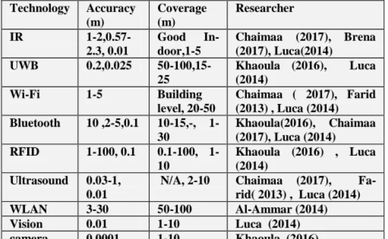
Table 1: Comparison between LPS
Technology Accuracy (m) Coverage (m) Researcher IR 1-2,0.57-2.3, 0.01 Good In-door,1-5 Chaimaa (2017), Brena (2017), Luca(2014) UWB 0.2,0.025 50-100,15-25 Khaoula (2016), Luca (2014) Wi-Fi 1-5 Building level, 20-50 Chaimaa ( 2017), Farid (2013) , Luca (2014) Bluetooth 10 ,2-5,0.1 10-15,-, 1-30 Khaoula(2016), Chaimaa (2017), Luca (2014) RFID 1-100, 0.1 0.100, 1-10 Khaoula (2016) , Luca (2014) Ultrasound 0.03-1, 0.01
N/A, 2-10 Chaimaa (2017),
Fa-rid( 2013) , Luca (2014)
WLAN 3-30 50-100 Al-Ammar (2014)
Vision 0.01 1-10 Luca (2014)
camera 0.0001 1-10 Khaoula (2016)
In Table 1 two performance parameters have been choice for the comparison of LPS technologies with researcher and year.
Table 2: Comparison between Position Estimation Techniques
Technolo-gy Techniques Typical environ-ment Researcher IR Proximity TOA, Thermal imaging active beacons Indoor Chaimaa(2017), Farid(2013) , khaoula(2016)
UWB TOA, TDOA,
Simulation
Indoor Khaoula (2016),
Mo-TDOA hamed R. Mahfouz (2008)
Wi-Fi Proximity TOA,
TDOA, RSSI, Theoretical propagation model, finger-printing Building level, In-door Chaimaa (2017),Farid(2013) , khaolua (2016)
Bluetooth RSSI,
Theoreti-cal propagation model, CoO
indoor Chaimaa (2017),
Farid(2013) ,
Khaoula(2016)
RFID Proximity TOA,
RSSI ,Theoretica l propagation model, CoO indoor Chaimaa (2017),Farid(2013) , khaolua (2016)
ultrasound TOA, AOA indoor Chaimaa
(2017),Farid(2013)
WLAN RSSI - Al-Ammar(2014)
Vision image processing
algorithm
indoor Luca(2014)
Camera angle measure indoor khaoula(2016)
In table 2, there are many techniques are used for LPS but the common techniques in LPS are TOA, TDOA, RSSI.
7. Conclusion
This review paper of LPS includes technologies, techniques, per-formance metrics has been presented. On the other hand, the com-parison between LPS technologies and techniques used based on those technologies are also discussed. Furthermore, the LPS‟s applications that have been done by previous researches such as human tracking, object tracking, animal tracking and automatic guide vehicle (AGV) tracking are discussed. Different approaches of this technology were discussed and several limitations among them were observed. However, the best choice is to compromise the criteria, which can achieve by using UWB technology to get accuracy in centimeter level with using either TOA or TDOA technique.
Acknowledgement
The authors wish to thank to Ministry of Higher Education, Ma-laysia (MoHE) and Universiti Teknologi MaMa-laysia (UTM) for providing the funding and facilities to conduct this research with Project No. R.J130000.7824.4F839 and Q.J130000.2524.20H25.
References
[1] Aitenbichler, E. and Mühlhäuser, M. (2003) „An IR local positioning
system for smart items and devices‟, Proceedings - 23rd International Conference on Distributed Computing Systems Workshops, ICDCSW 2003, pp. 334–339. doi: 10.1109/ICDCSW.2003.1203576.
[2] Al-Ammar, M. A. et al. (2014) „Comparative survey of indoor positioning technologies, techniques, and algorithms‟, Proceedings - 2014 International Conference on Cyberworlds, CW 2014, pp. 245–252. doi: 10.1109/CW.2014.41.
[3] Angrisani, L., Arpaia, P. and Gatti, D. (2017) „Analysis of localization technologies for indoor environment‟, 2017 IEEE International Workshop on Measurement and Networking, M and N 2017 - Proceedings, pp. 0–4. doi: 10.1109/IWMN.2017.8078385. [4] Basri, C. and El Khadimi, A. (2017) „Survey on indoor localization
system and recent advances of WIFI fingerprinting technique‟,
International Conference on Multimedia Computing and Systems -Proceedings, pp. 253–259. doi: 10.1109/ICMCS.2016.7905633. [5] Brena, R. F. et al. (2017) „Evolution of Indoor Positioning
Technologies: A Survey‟, Journal of Sensors, 2017. doi: 10.1155/2017/2630413.
[6] Brusnighan, D. A. et al. (1989) „Orientation aid implementing the global positioning system‟, Proceedings of the Fifteenth Annual Northeast Bioengineering Conference, (Lcd), pp. 33–34. doi: 10.1109/NEBC.1989.36684.
[7] Chabbar, H. and Mouhcine, C. (2017) „Indoor localization using
Wi-Fi method based on fingerprinting technique‟, IEEE, pp. 1–5. [8]Farid, Z. et al. (2014) „Leveraging existing WLAN infrastructure for
wireless indoor positioning based on fingerprinting and clustering technique‟, 13th International Conference on Electronics, Information, and Communication, ICEIC 2014 - Proceedings. doi: 10.1109/ELINFOCOM.2014.6914415.
[9] Farid, Z., Nordin, R. and Ismail, M. (2013) „Recent advances in wireless indoor localization techniques and system‟, Journal of Computer Networks and Communications, 2013. doi: 10.1155/2013/185138.
[10] Galler, S. et al. (2007) „Combined AOA / TOA UWB localization‟, pp. 1049–1053.
[11] Gulden, P., Roehr, S. and Christmann, M. (2009) „An overview of wireless local positioning system configurations‟, IEEE MTT-S International Microwave Workshop Series on Wireless Sensing, Local Positioning and RFID, Proceedings, IMWS 2009 - Croatia. doi: 10.1109/IMWS2.2009.5307894.
[12] Güvenç, I. and Chong, C. C. (2009) „A survey on TOA based wireless localization and NLOS mitigation techniques‟, IEEE Communications Surveys and Tutorials, 11(3), pp. 107–124. doi: 10.1109/SURV.2009.090308.
[13] Hu, S., Kang, M. and She, C. (2017) „Vehicle positioning based on UWB technology‟, Journal of Physics: Conference Series, 887, p. 12069. doi: 10.1088/1742-6596/887/1/012069.
[14] Jiang, S. (2010) „Ultra-Wide Band technology applications in construction : a review‟, pp. 207–213.
[15] K. Kang-Wook, P. Myung-Gon, T. Hishikawa, H. Junghee, and L. and Chang-Gun (2012) „“Exploiting Ultrasonic Reflections for Improving Accuracy of Indoor Location Tracking,”‟ 9th Int. Conf. Ubiquitous Intelligence & Computing and 9th Int. Conf. on Autonomic & Trusted Computing (UIC/ATC), Fukuoka, p. p. 87– 95,.
[15] Keefe, brian o (2017) „Finding Location with Time of Arrival and Time Difference of Arrival Techniques‟, pp. 1–3.
[16] Krishnamurthy., K. K. and P. (2004) „Properties of indoor received signal strength for wlan location fingerprinting. In Mobile and Ubiquitous Systems: Networking and Services, 2004. MOBIQUITOUS 2004 on‟, . The First Annual International Conference on IEEE, p. 14–23.
[17] Link, S.- (2003) „POSITIONING USING TIME-DIFFERENCE OF ARRIVAL MEASUREMENTS Fredrik Gustafsson and Fredrik Gunnarsson Department of Electrical Engineering‟, Electrical Engineering, pp. 8–11.
[18] Liu, M. et al. (2017) „RFID Indoor Localization System for Tag and Tag- free Target based on Interference‟, pp. 372–376.
[19] Mainetti, L., Patrono, L. and Sergi, I. (2014) „A survey on indoor positioning systems‟, 2014 22nd International Conference on Software, Telecommunications and Computer Networks (SoftCOM), pp. 111–120. doi: 10.1109/SOFTCOM.2014.7039067.
[20] Mannay, K. et al. (2016) „Location and Positioning Systems : Performance and Comparison‟, pp. 16–18.
[21] Medina.C, Segura. J. C., and D. la T. . (2013) „Ultrasound indoor positioning system based on a low-power wireless sensor network providing sub-centimeter accuracy,‟ Sensors (Switzerland), 13, n, pp. 3501–3526.
[22] Miši, J. (2015) „An Overview of Wireless Indoor Positioning Systems‟, 14(March), pp. 301–306.
[23] Ravindra, S. and , Jagadeesha, S. N. (2013) „Time of Arrival Based Localization in Wireless Sensor Networks: A Linear Approach‟,
Signal & Image Processing : An International Journal, 4(4), pp. 13–30. doi: 10.5121/sipij.2013.4402.
[24] Ren, A. et al. (2017) „A Study of Indoor Positioning Based on UWB Base-Station Configurations‟, pp. 1939–1943.
[25] Zheng.Y, Zhou.Z, A. . (2013) „From RSSI to CSI: Indoor localization via channel response.‟, ACM Computing Surveys (CSUR) 46.2.