Accelerators for Packet Classification
and String Matching
by
Alan Kennedy, B.Eng.
Submitted in partial fulfilment of the requirements for the Degree of Doctor of Philosophy
Dublin City University School of Electronic Engineering
Supervisor: Dr. Xiaojun Wang September 2010
I hereby certify that this material, which I now submit for assessment on the programme of study leading to the award of Doctor of Philosophy is entirely my own work, that I have exercised reasonable care to ensure that the work is original, and does not to the best of my knowledge breach any law of copyright, and has not been taken from the work of others save and to the extent that such work has been cited and acknowledged within the text of my work.
Signed:. . Alan Kennedy (Candidate) ID No.:. . Date: . .
Firstly, I would like to thank my supervisor Dr. Xiaojun Wang for taking me on as his student and giving me a great deal of help, support and guidance during my time in Dublin City University. I would also like to thank my colleagues in the Network Processing Group for making the lab an enjoyable place to work and for giving me their technical advice whenever needed. My gratitude also goes to Prof. Bin Liu and the other members of the Broadband Switching Laboratory in Tsinghua University with whom I collaborated.
I would like to give a special thanks to my parents for making this work possible by giving me their love, help and financial support during my seemingly never-ending education. Finally I would like to thank Lisa for her love, help and encouragement during the duration of my Ph.D., and for her understanding of the long hours spent in the lab.
Declaration... i
Acknowledgments ... ii
Table of Contents ...iii
Abstract... vii
List of Figures... viii
List of Tables ... xi
List of Acronyms ... xii
Publications and Patents Arising from Work ... xiv
Chapter 1 - Introduction ... 1
1.1 Motivation ... 1
1.2 Network Overview ... 3
1.3 Packet Processing Bottlenecks ... 6
1.3.1 Packet Classification... 7
1.3.2 Deep Packet Inspection... 8
1.3.3 Technical Challenges ... 9 1.4 Contributions ... 11 1.5 Thesis Organisation ... 13 1.6 Summary... 14 Chapter 2 - Background ... 15 2.1 Introduction ... 15
2.2 Packet Classification Rulesets ... 16
2.3 Analysis of Software Approaches to Packet Classification... 17
2.3.1 Algorithmic Approaches... 18
2.4 Deep Packet Inspection Systems ... 30
2.4.1 Snort... 31
2.4.2 Current Fixed String Matching Approaches ... 32
2.4.3 Conclusions... 34 2.5 Hardware-Based Platforms... 34 2.5.1 ASIC ... 35 2.5.2 FPGA ... 35 2.5.3 TCAM... 36 2.5.4 Conclusions... 38
2.6 Low Power Design ... 38
2.6.1 Types of Power Dissipation ... 39
2.6.2 Power Benchmarking... 43
2.6.3 Low Power Design Techniques ... 44
2.7 Summary... 47
Chapter 3 - Packet Classification Architectures ... 48
3.1 Introduction ... 48
3.2 Decision Tree-Based Packet Classification ... 49
3.2.1 Building a Decision Tree ... 51
3.2.2 Heuristics Used to Reduce Memory Usage ... 54
3.3 Algorithmic Modifications ... 56 3.3.1 Cutting Scheme... 57 3.3.2 Region Compaction ... 59 3.3.3 Rule Storage... 62 3.4 Cut Selection ... 64 3.5 Memory Organisation... 66
3.5.1 Ultra-Wide Memory Words... 66
3.5.2 Reduced Width Memory Words ... 68
3.6 Packet Classification Engine ... 73
3.6.1 Architecture of Engine Using Ultra-Wide Memory Words... 74
3.6.2 Architecture of Engines Using Reduced Width Memory Words... 77
3.7 Configuration of Multiple Engines Operating in Parallel... 82
3.7.1 Architecture of Packet Buffer ... 83
3.7.2 Architecture of Sorter Logic Block... 84
3.8.1 Hardware Implementation Parameters... 89
3.8.2 Memory Usage and Worst Case Number of Memory Accesses... 91
3.8.3 Throughput vs. Power Consumption ... 94
3.8.4 Evaluation Against Prior Art ... 97
3.9 Summary of Contributions ... 100
Chapter 4 - Frequency Scaling Architecture... 102
4.1 Introduction ... 102
4.2 Analysis of Real Traces... 103
4.2.1 Processing Needs ... 105
4.2.2 Classifier Utilisation ... 106
4.3 Methods for Reducing Power Consumption... 107
4.3.1 Clock Gating/Turning Off Unused Processing Elements ... 107
4.3.2 Voltage/Frequency Scaling... 108
4.4 Adaptive Clocking Scheme ... 109
4.4.1 Method for Reducing Frequency Switching ... 110
4.4.2 Adaptive Clocking Unit Architecture ... 113
4.5 Low Power Architecture for Packet Classification ... 115
4.5.1 Hardware Implementation Parameters... 115
4.5.2 Power Consumption... 117
4.6 Performance Testing Using Synthetic Traces... 122
4.6.1 Power Savings... 124
4.7 Summary of Contributions ... 126
Chapter 5 - String Matching Architecture ... 128
5.1 Introduction ... 128
5.2 String Matching Using Deterministic Finite Automaton... 129
5.3 Memory Reduction ... 131
5.3.1 DFA Memory Usage Observations... 132
5.3.2 Insertion of Default Transition Pointers ... 133
5.3.3 Algorithm for Building Search Structure... 138
5.4 Memory Organisation and Hardware Architecture ... 142
5.4.1 Memory Layout ... 142
5.4.2 Hardware Accelerator Architecture ... 144
5.5.1 Characteristics of Snort Ruleset Used in Testing... 151
5.5.2 Hardware Implementation Parameters... 152
5.5.3 Transition Pointer Reduction ... 154
5.5.4 Throughput vs. Power Consumption ... 157
5.5.5 Evaluation Against Prior Art ... 158
5.6 Summary of Contributions ... 160
Chapter 6 – Conclusions and Future Work... 161
6.1 Conclusions ... 161
6.1.1 Motivation for Proposed Research – A Summary ... 161
6.1.2 Summary of Thesis Contributions ... 162
6.1.3 Packet Classification... 162
6.1.4 Frequency Scaling... 164
6.1.5 String Matching ... 164
6.2 Future Work... 165
6.2.1 Multi-Match Packet Classification ... 166
6.2.2 Regular Expression Matching... 166
6.2.3 Reducing the Fixed String Matching Hardware Accelerator’s Power.. 167
Appendix A – Power Usage ... 168
Energy Efficient Hardware Accelerators for Packet Classification
and String Matching
Alan Kennedy
This thesis focuses on the design of new algorithms and energy efficient high throughput hardwareaccelerators that implement packet classification and fixed string matching. These computationally heavy and memory intensive tasks are used by networking equipment to inspect all packets at wire speed. The constant growth in Internet usage has made them increasingly difficult to implement at core network line speeds. Packet classification is used to sort packets into different flows by comparing their headers to a list of rules. A flow is used to decide a packet’s priority and the manner in which it is processed. Fixed string matching is used to inspect a packet’s payload to check if it contains any strings associated with known viruses, attacks or other harmful activities.
The contributions of this thesis towards the area of packet classification are hardware accelerators that allow packet classification to be implemented at core network line speeds when classifying packets using rulesets containing tens of thousands of rules. The hardware accelerators use modified versions of the HyperCuts packet classification algorithm. An adaptive clocking unit is also presented that dynamically adjusts the clock speed of a packet classification hardware accelerator so that its processing capacity matches the processing needs of the network traffic. This keeps dynamic power consumption to a minimum. Contributions made towards the area of fixed string matching include a new algorithm that builds a state machine that is used to search for strings with the aid of default transition pointers. The use of default transition pointers keep memory consumption low, allowing state machines capable of searching for thousands of strings to be small enough to fit in the on-chip memory of devices such as FPGAs. A hardware accelerator is also presented that uses these state machines to search through the payloads of packets for strings at core network line speeds.
Fig. 1.1. TCP/IP model showing packets being sent between end hosts through a router. 5
Fig. 1.2. Overview of the Internet architecture. ... 6
Fig. 2.1. Structure of rules used for packet classification. ... 16
Fig. 2.2. HiCuts decision tree (left) and its geometric representation (right). ... 19
Fig. 2.3. HyperCuts decision tree (left) and its geometric representation (right)... 20
Fig. 2.4. Extended Grid-of-Tries with Path Compression. ... 21
Fig. 2.5. Recursive Flow Classification search structure. ... 22
Fig. 2.6. Tuple Space Search with Tuple Pruning. ... 23
Fig. 2.7. Memory needed for the search structures. ... 25
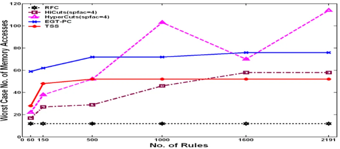
Fig. 2.8. Worst case number of memory accesses needed to classify a packet... 26
Fig. 2.9. Energy used building the search structure. ... 27
Fig. 2.10. Average energy needed to classify a packet. ... 28
Fig. 2.11. Total number of packets classified in one second. ... 29
Fig. 2.12. Charging and discharging of a capacitive load... 39
Fig. 2.13. Switching characteristics of a CMOS inverter. ... 40
Fig. 2.14. Static vs. dynamic power. ... 42
Fig. 2.15. Implementation of a parallel and pipelined three input adder. ... 45
Fig. 3.1. Cuts performed to the root node of a decision tree... 52
Fig. 3.2. Cuts performed to the internal node of a decision tree. ... 53
Fig. 3.3. Traversing a decision tree to find a matching rule... 54
Fig. 3.4. Heuristics used by HyperCuts to reduce memory consumption... 55
Fig. 3.5. Region division with and without region compaction. ... 60
Fig. 3.6. Compacting of a region through pre-cutting... 62
Fig. 3.7. Encoding scheme used for source and destination IP address. ... 63
Fig. 3.8. Layout of information needed to match a packet header to a rule... 64
Fig. 3.9. Architecture of cut selection logic. ... 65
Fig. 3.13. Layout of root node pointers when using reduced width internal memory. .... 69
Fig. 3.14. Layout of internal node when using reduced width internal memory. ... 70
Fig. 3.15. Layout of leaf node when using reduced width internal memory. ... 70
Fig. 3.16. Layout of root node pointers when using reduced width external memory. ... 71
Fig. 3.17. Layout of internal node when using reduced width external memory... 71
Fig. 3.18. Layout of leaf node when using reduced width external memory... 72
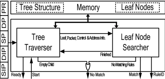
Fig. 3.19. Block diagram of the architecture used by the packet classification engines. . 73
Fig. 3.20. Operation of engine using ultra-wide memory words. ... 74
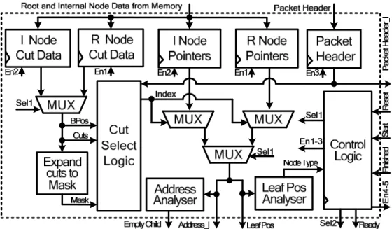
Fig. 3.21. Architecture of tree traverser using ultra-wide memory words. ... 75
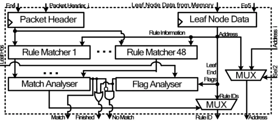
Fig. 3.22. Architecture of leaf node searcher using ultra-wide memory words. ... 76
Fig. 3.23. Operation of engine using reduced width internal memory... 77
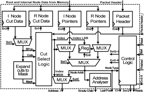
Fig. 3.24. Architecture of tree traverser using reduced width internal memory. ... 78
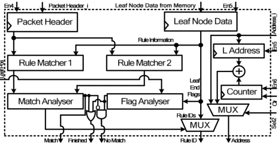
Fig. 3.25. Architecture of leaf node searcher using reduced width internal memory. ... 79
Fig. 3.26. Operation of engine using reduced width external memory... 80
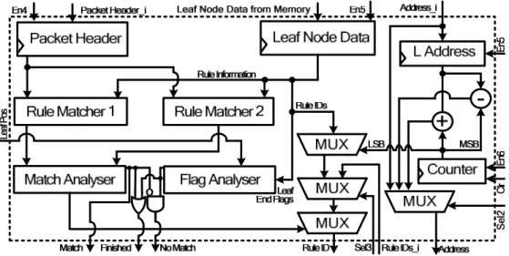
Fig. 3.27. Architecture of leaf node searcher using reduced width external memory. .... 81
Fig. 3.28. Architecture of packet buffer used by packet classifiers. ... 84
Fig. 3.29. Architecture of sorter logic block used by packet classifiers. ... 85
Fig. 3.30. Architecture of hardware accelerator using ultra-wide memory words... 86
Fig. 3.31. Architecture of hardware accelerator using reduced width memory words. ... 88
Fig. 3.32. Power consumed by packet classifiers implemented using Cyclone III... 95
Fig. 3.33. Power consumed by packet classifiers implemented using Stratix III. ... 96
Fig. 4.1. Throughput of a 24-hour trace from the CENIC HPR backbone link. ... 104
Fig. 4.2. Percentage of classifier idle time when classifying packets from the CENIC trace. 106 Fig. 4.3. Switching sequences with all states used... 112
Fig. 4.4. Switching sequences with selected states used... 112
Fig. 4.5. Architecture of the adaptive clocking unit... 113
Fig. 4.6. Architecture of low power packet classifier. ... 115
Fig. 4.7. Power used by the ASIC implementation of the low power classifier. ... 118
Fig. 4.8. Power used by the Cyclone III implementation of the low power classifier. .. 119
Fig. 4.9. Power used by the Stratix III implementation of the low power classifier... 120
Fig. 4.10. Throughput of the synthetic 2.5 Gbps, 10 Gbps and 40 Gbps packet traces. 122 Fig. 4.11. ASIC power usage when classifying packets from synthetic traces... 124
Fig. 4.12. Cyclone III power usage when classifying packets from synthetic traces... 125
Fig. 5.3. Use of default transition pointers to states at a depth of one. ... 134
Fig. 5.4. Use of default transition pointers to states at a depth of two. ... 135
Fig. 5.5. Use of default transition pointers to states at a depth of three. ... 137
Fig. 5.6. Recording a state’s depth, character value and forward pointing transitions. . 139
Fig. 5.7. Recording a state’s non-forward pointing transitions... 140
Fig. 5.8. Recording the strings matched if a state is entered... 141
Fig. 5.9. Memory organisation of information needed to store a state. ... 142
Fig. 5.10. Possible positioning of the state types in memory and their bit size. ... 143
Fig. 5.11. Organisation of a lookup table memory word. ... 144
Fig. 5.12. Architecture of a string matching block. ... 145
Fig. 5.13. Architecture of the string matching engine... 148
Fig. 5.14. Architecture of the string matching scheduler. ... 150
Fig. 5.15. Distribution of string lengths for unique strings found in Snort ruleset. ... 151
Fig. 5.16. Throughput of the string matchers when using different sized rulesets. ... 156
Fig. 5.17. Power consumed by Cyclone III implementation of the string matcher. ... 157
Fig. 5.18. Power consumed by Stratix III implementation of the string matcher. ... 158
Fig. A. 1. Power usage of ASIC low power classifier using 5,000 rules. ... 168
Fig. A. 2. Power usage of ASIC low power classifier using 25,000 rules. ... 168
Fig. A. 3. Power usage of Cyclone III low power classifier using 5,000 rules... 169
Fig. A. 4. Power usage of Stratix III low power classifier using 5,000 rules. ... 169
Table 2.1. Sample ruleset containing five rules. ... 18
Table 3.1. Sample ruleset containing nine rules. ... 51
Table 3.2. Maximum number of cuts allowed by the cutting scheme. ... 59
Table 3.3. FPGA resource utilisation for packet classification hardware accelerators.... 90
Table 3.4. Memory usage (bits) and worst case number of memory accesses. ... 92
Table 3.5. Performance comparison of packet classification hardware accelerators... 98
Table 4.1. Statistics on packet sizes in the CENIC HPR backbone trace. ... 104
Table 4.2. Clock speed associated with each state... 110
Table 4.3. FPGA memory and logic utilisation of low power packet classifier. ... 117
Table 5.1. FPGA resource utilisation for string matching hardware accelerators. ... 152
Table 5.2. Reduction in number of transition pointers stored in states... 154
ACL – Access Control List ACU – Adaptive Clocking Unit
ASCII – American Standard Code for Information Interchange ASIC – Application Specific Integrated Chip
CENIC – Corporation for Education Network Initiatives in California CMOS – Complementary Metal–Oxide–Semiconductor
CS – Connecting State DDR2 – Double Data Rate 2
DFA – Deterministic Finite Automaton DPI – Deep Packet Inspection
DRAM – Dynamic Random Access Memory
EGT-PC – Extended Grid-of-Tries with Path Compression FPGA – Field Programmable Gate Array
FW – Firewall
Gbps – Gigabits per second
HDL – Hardware Description Language HPR – High Performance Research IPC – Internet Protocol Chain IPTV – Internet Protocol Television ISP – Internet Service Provider LPM – Longest Prefix Match
Mbps – Megabits per second Mpps – Million packets per second MSB – Most Significant Bit
MTU – Maximum Transmission Unit NAT – Network Address Translation
NLANR – National Laboratory for Applied Network Research OC – Optical Carrier
OSI – Open System Interconnect PE – Processing Element PLL – Phase Lock Loop QoS – Quality of Services RAM – Random Access Memory RFC – Recursive Flow Classification RISC – Reduced Instruction Set Computer RTL – Register Transfer Level
SDRAM – Synchronous Dynamic Random Access Memory SRAM – Static Random Access Memory
TCAM – Ternary Content Addressable Memory TCP – Transmission Control Protocol
TCP/IP – Transmission Control Protocol/Internet Protocol TSMC – Taiwan Semiconductor Manufacturing Company TSS – Tuple Space Search
UDP – User Datagram Protocol VCD – Value Change Dump VoIP – Voice over Internet Protocol VPN – Virtual Private Network
Published Papers
D. Bermingham, A. Kennedy, X. Wang, and B. Liu, “Architectures for the Whirlpool Hashing Algorithm,” In Proc. of the China-Ireland International
Conference on Information and Communications Technologies (CIICT),
Hangzhou, 8-19 Oct. 2006, pp.201-205.
D. Bermingham, A. Kennedy, X. Wang, and B. Liu, “A Survey of Network Processor Workloads,” In Proc. of the China-Ireland International Conference on Information and Communications Technologies (CIICT), Dublin, 28-29 Aug. 2007, pp.354-361.
A. Kennedy, D. Bermingham, X. Wang, and B. Liu, “Power Analysis of Packet Classification on Programmable Network Processors,” In Proc. of the IEEE International Conference on Signal Processing and Communications (ICSPC), Dubai, 24-27 Nov. 2007, pp.1231-1234.
A. Kennedy, X. Wang and B. Liu, “Energy Efficient Packet Classification Hardware Accelerator,” In Proc. of the 22nd IEEE International Parallel & Distributed Processing Symposium (IPDPS), Florida, 14-18 April 2008.
A. Kennedy, X. Wang, Z. Liu and B. Liu, “Frequency Scaling for Multidimensional Packet Classification,” In Proc. of the China-Ireland International Conference on Information and Communications Technologies (CIICT), Beijing, 26-28 Sept. 2008, pp. 383-387.
A. Kennedy, X. Wang, Z. Liu and B. Liu, “Low Power Architecture for High Speed Packet Classification,” In Proc. of the 4th ACM/IEEE Symposium on Architectures for Networking and Communications Systems (ANCS), San José, 6-7 Nov. 2008, pp. 131-140.
Computer Communications and Networks (ICCCN), San Francisco, 2-6 Aug. 2009.
Z. Liu, A. Kennedy, O. Ormond, X. Wang, “Power-Efficient Packet Classifier for Next-Generation Routers”, European Research Consortium for Informatics and Mathematics (ERCIM ), News, No. 79, Oct. 2009.
A. Kennedy, X. Wang, Z. Liu and B. Liu, “Ultra-High Throughput String Matching for Deep Packet Inspection,” In Proc. of the Conference on Design, Automation and Test in Europe (DATE), Dresden, 8-12 March 2010.
Patent Application
Patent application: Adaptive clocking system for a packet classifier. UK Patent application reference number: D07-396-27GB. Applicants: Alan Kennedy, Xiaojun Wang and Zhen Liu.
1.1
Motivation
The increasing growth in Internet usage has been aided by its ease of access through a wide range of devices such as desktops, notebooks, netbooks, mobile phones, portable multimedia players and even watches, putting a real strain on the networking equipment needed to inspect and process the resultant traffic. A survey carried out by Internet World Stats [1] shows how this ease of access has allowed Internet penetration to reach 24.7% of the world’s population as of June 2009, with the number of Internet users growing by 462% between December 2000 and June 2009. This survey also showed that 13.65% of Internet users are from the USA, which is an important statistic when it is considered that the total amount of energy used in the year 2000 by various networking devices in the USA equated to the yearly output of a typical nuclear reactor unit [2]. This would place the current amount of energy used by networking devices worldwide to be the same as the yearly output of 17 typical nuclear reactor units. Power consumption should therefore be a key concern when designing any new networking equipment for the purpose of processing the ever-increasing amount of network traffic. This is in order to slow the rapidly growing costs of running the networking equipment and to reduce their carbon footprint.
Analysis in [3] demonstrated that up to 50% of an Internet Service Provider’s (ISP) maintenance costs are power related, including the electricity consumed by the routers and the corresponding cooling systems and so on. A company that manufactures power efficient networking equipment would therefore have a distinct advantage over their competitors when selling to Internet Service Providers as they could reduce their maintenance costs. Networking equipment
used to process network traffic such as high-end routers like the Cisco ASR 9010 router can consume up to 7,600 Watts, with each line card in the router consuming up to 685 Watts [4]. Due to their large integration scale and high speed, network processors deployed on a router’s line card can use a large percentage of its power budget. These network processors can come in a wide range of configurations, with varying numbers of processing engines. These processing engines can run at speeds in the GHz range, consuming large amounts of power. The EZchip NP-1, for example, contains 64 processing engines [5] while the Intel IXP2800 contains 16 and has a peak power consumption of 30W [6]. Each line card on a router typically contains two network processors for ingress and egress processing, and a router can contain multiple line cards.
These network processors are used to process packets as they pass through the network, carrying out applications such as packet fragmentation and reassembly, queue management, header manipulation, encryption, forwarding, classification and pattern matching. The growing number of applications and services that need to be carried out, along with the increase in line rates, have placed the network processor under increased pressure. Relieving this pressure through the addition of extra processing capacity is not an easy task due to factors such as tight power budgets and silicon limitations. Ramping up clock speeds to gain extra performance is difficult due to physical limitations in the silicon used to manufacture these devices, while increasing the number of processing cores used to process the traffic can cause difficulty when it comes to writing the software needed to control the network processor. Both these approaches can also lead to large increases in power consumption due to the extra heat generated by increasing the clock speeds and the extra transistors needed to increase the number of processing cores.
The use of dedicated hardware accelerators designed to carry out the most computationally heavy tasks on a network processor can help to reduce power consumption while increasing processing capacity. This is because a hardware accelerator can be designed to have a smaller transistor footprint than that of the general purpose processors used as processing engines in multi-core network processors. Hardware accelerators can also process greater amounts of data than a
general purpose processor while running at much slower clock speeds as they are typically optimised to carry out a specific task. This reduction in clock speed and transistor count will lead to large savings in power consumption.
Offloading the most frequently occurring and computationally heavy tasks from a network processor’s processing engines will help to prevent it from becoming a traffic bottleneck on a network, allowing for increases in achievable line rates. It will also leave the processing engines free to carry out new emerging services and protocols as they are introduced. These hardware accelerators can be placed onboard a network processor or as an external processing unit.
An explanation of the network architecture currently used by the Internet is given in Section 1.2. Section 1.3 outlines existing and emerging traffic processing bottlenecks in this architecture, which the work presented in this thesis removes through the implementation of energy efficient high throughput hardware accelerators. This section also explains the technical challenges that make the removal of these bottlenecks a difficult task. The research objectives of the thesis are stated in Section 1.4, along with the main contributions made. The thesis structure is given in Section 1.5, with Section 1.6 summarising.
1.2
Network Overview
The architecture of the communications network used by the Internet consists of end hosts, which are devices such as desktop computers, notebooks, mobile phones, etc. These end hosts communicate with each other through a web of communication mediums such as fibre optic cables, satellites and wire cables. The information sent between these end hosts is broken into pieces of data known as packets. These packets are routed through the various mediums in the communication network using devices known as routers. The communications network that these packets are sent across is governed by written standards documents known as protocols. These protocols are used to ensure the correct and efficient interoperation of the heterogeneous groups of computer networks using the Internet. They detail all aspects of communication such as the format of packets and how these packets should be handled when received. The architecture of the communications network is divided up into several distinct layers, with
each layer using one or more different protocols. A protocol suite is formed when the protocols from different layers are combined. The communications network was originally divided into seven layers before the introduction of the Internet. This was known as the Open System Interconnect (OSI) Reference Model [7]. The Internet replaced this with a five-layered model known as the Transmission Control Protocol/Internet Protocol (TCP/IP) model. Each layer is described from top to bottom as follows, where a layer provides a service to the layer above it and uses the service of the layer below it.
• Layer 5 is the highest layer and is known as the Application Layer. This layer represents the reason for communicating and is where the data being transferred is presented. It is used for applications such as file transfers, emailing or web browsing. It is the layer that the user most closely interacts with and is responsible for implementing the protocols that were carried out by the presentation and session layers. These layers were included in the OSI model but no longer exist in the TCP/IP model.
• Layer 4 is known as the Transport Layer and it is used to establish, manage and end a connection between hosts. It is also used to help make sure that packets arrive in the correct order and are error free. The transport layer is used to decide if packets should be sent using a Transmission Control Protocol (TCP) or User Datagram Protocol (UDP). TCP can guarantee data integrity through the use of a checksum. It also guarantees delivery as it will retransmit packets until the receiver acknowledges that it has received them. This makes TCP ideal for services such as the sending of email or file transfer, where the delivery of all packets is essential. UDP also guarantees data integrity through the use of a checksum, but does not guarantee the delivery of a packet. For this reason UDP is used for sending information where the non-delivery of a few packets is not important. Examples include media applications such as Voice over Internet Protocol (VoIP) or Internet Protocol Television (IPTV).
• Layer 3 is the Internet Layer, which is used to determine how packets should be sent from the source network to the destination network through the handling of the routing. This is done by sending packets from one router to the next until the final network is reached.
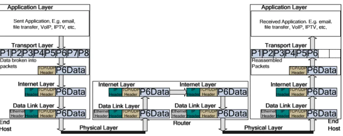
P2 P1 P3P4P5P6P7P8 P6Data TCP/UDP Header P6Data TCP/UDP Header IP Header P6Data TCP/UDP Header IP Header P6Data TCP/UDP Header P6Data TCP/UDP Header IP Header P6Data TCP/UDP Header IP Header P6Data TCP/UDP Header IP Header P6Data TCP/UDP Header P6Data TCP/UDP Header IP Header P2 P1 P3P4P5 P6Data TCP/UDP Header Ethernet Header Ethernet Header Ethernet Header IP Header Ethernet Header IP Header P6
Fig. 1.1. TCP/IP model showing packets being sent between end hosts through a router.
• Layer 2 is called the Data Link Layer. It is the layer responsible for sending information between the various nodes in a communication network through the use of frames. This may involve the breaking up of large packets into multiple frames.
• Layer 1 is the lowest layer and is known as the Physical Layer. It provides electrical, optical and mechanical details about how the information should be sent across the network as bits using the various communication mediums. An example of how the TCP/IP model can be used to send information from one end host to another is shown in Fig. 1.1. This model is based on the end-to-end design principles proposed by Saltzer et. al. [8]. They state that the majority of the communication protocols should take place at the end points of a communication system or as close to the end points as is possible. This is because the resources at the centre of the communications system will be shared by many end hosts and will therefore not have as much time to process the information being transmitted as the resources near the edge of the system, which are not so heavily shared. The end hosts are where most of the processing on a packet occurs. This means that they require access to the full content of the packets being sent and received. This content includes the packet header and payload (the data being sent) information. A packet being sent by an end host will pass through an edge network where the packets sent by all end hosts in this network gather at an edge router. These edge networks can operate at Gigabit rates, with examples of such networks including university campuses or large company headquarters. The high rates at whichthese networksoperateandalack ofprocessingcapacitytypically
Fig. 1.2. Overview of the Internet architecture.
only give an edge router time to inspect a packet’s header, allowing it to forward packets and implement vital tasks such as firewalls and Quality of Services (QoS). A packet can be sent from the edge router to an end host in the same edge network, from an edge network to another edge network or more often to the core of the network where it is processed by core routers. The core of a network usually operates at link speeds of 10 Gigabits per second (Gbps), with 40 Gbps links also in use. At these speeds there is very little time to process a packet as it passes through a core router. A core router will typically not have time to even inspect the entire packet header and will only have time to inspect the destination IP address, allowing the router to forward a packet to its next hop. Fig. 1.2 shows the topology of the end-to-end communications network used by the Internet.
1.3
Packet Processing Bottlenecks
The work presented in this thesis centres around the design and implementation of energy efficient hardware accelerators that can relieve a network processor’s processing engines of some of the most power hungry and computationally hard networking tasks. This is done to reduce power consumption and to increase a network processor’s throughput, thus preventing traffic bottlenecks. A network processor has to carry out many computationally heavy tasks such as packet fragmentation and queue management. The two tasks targeted for hardware acceleration in this thesis are packet classification and fixed string matching, which is used in Deep Packet Inspection (DPI). These tasks are chosen because
they must be carried out on every packet and require search structures that use large amounts of memory, making them power hungry.
1.3.1 Packet Classification
Single-match, multi-field packet classification is the process of mapping a packet to one of a finite set of flows or categories using information from the packet’s header. This information includes the source and destination IP addresses, which are matched using longest prefix matching, the source and destination port numbers, which are matched using range matching and the protocol number, which can be an exact match or wildcard. These fields are extracted from the Transport and Internet Layers of a packet’s header. Packets belonging to the same flow match a predefined rule and are processed in the same way by the router’s line card. The classifier will select the flow with the highest priority in the case where there are multiple rule matches. This type of packet classification usually takes place at edge routers, implementing a plethora of services such as:
• Firewalls, which are used to protect the end hosts of an edge network by blocking incoming and outgoing packets whose header information does not comply with policy. This helps to prevent harmful activity such as the spread of viruses and worms. It can also be used by an ISP to block customers from accessing prohibited websites.
• Traffic monitoring, which allows an ISP to monitor an end host’s network usage, allowing it to bill appropriately.
• Traffic shaping, where some packets are delayed and others are allowed to pass through quickly. This can be used by an ISP to give priority to customers who pay more for a higher bandwidth and to allow time-sensitive traffic such as VoIP and IPTV packets to pass through quickly.
• Traffic policing, which can be used by an ISP to prevent end hosts from exceeding their maximum bandwidth limit.
• Network Address Translation (NAT), allowing multiple computers on an edge network to share a single IP address. The NAT system will rewrite the packet’s header if it matches a certain flow.
• Load balancing, where large websites increase performance by running copies of their website on different servers. Packets classification is used to direct packets in a particular flow to the server with the smallest load.
The process of packet classification is an NP-hard problem, which is further complicated by the fact that all packets entering a router must be processed at wire speed. The large number of services being provided by network providers makes this problem even more difficult as rulesets containing thousands of rules are needed. Software approaches to packet classification use various algorithms [9, 10, 11, 12, 13, 14, 15, 16, 17, 18, 19] which are run on the processing engines of multi-core network processors. The most common hardware approaches at high throughput packet classification include the use of power hungry memories such as Ternary Content Addressable Memory (TCAM) [20].
1.3.2 Deep Packet Inspection
Network intrusion detection/prevention systems used for the deterrence of malicious attacks depend heavily upon DPI. DPI involves searching a packet’s header and payload against thousands of rules to detect a possible attack. The end-to-end architecture of the Internet means that the processing of any Application Layer data such as the packet content can only take place at end hosts and edge routers. This is because core routers do not have the processing capacity needed to inspect the entire content of a packet at wire speed. The lack of intrusion detection systems in a network leaves end hosts particularly vulnerable to attacks from malware, which is malicious software that is designed to infiltrate a computer without the owner’s permission. It can be used for many purposes such as the destroying of files on a hard disk or the collection of passwords and credit card details. End hosts are also vulnerable to Internet Bots, used to carry out tasks such as the spreading of spam email.
The lack of intrusion detection systems in a network also leaves it vulnerable to viruses or worms. Slammer, the fastest spreading worm in history, infected over 75,000 hosts in only a 10-minute period [21], doubling in size every 8.5 seconds. The worm did not contain malicious content but was designed to overload a network, slowing down Internet speeds and even causing the loss of connection
for some end hosts. Another worm that caused mass damage by Denial of Service attacks was CodeRed, infecting 359,000 hosts in 14 hours [22]. With viruses/worms spreading at these speeds it would be unrealistic to expect the end hosts of a network to update their systems to new threats due to the slow time that it would take to react to the rapid attack. There is also the high cost in both the maintenance and lost work time due to updating the system.
The rules used for DPI in an intrusion detection system such as Snort [23] consist of two parts. The first part is a header rule, which involves performing 5-tuple multi-match packet classification on a packet’s header. Multi-match packet classification differs from single-match packet classification described in Section 1.3.1 in that it will return all matching rules rather than the rule with the highest priority. The second part is a content rule, where a specific string or strings must be searched for in a packet’s payload at given locations. Research in [24] shows that, for Snort, the fraction of time that network intrusion detection spends finding these strings on real traces is between 40-70%, using 60-80% of the instructions executed. These strings can be searched for using regular expression matching, fixed string matching, or both. The area of multi-match packet classification contains many solutions [25, 26, 27], with hardware accelerators reporting throughputs of up to 10 Gbps. There has also been much research done in the area of regular expression matching [28, 29, 30, 31, 32, 33, 34, 35], with implementations reporting throughputs of up to 5 Gbps.
The main aim of this thesis is to design hardware accelerators for the computationally heavy tasks of single-match, multi-field packet classification and fixed string matching. The work presented in this thesis is not therefore concerned with the problems of multi-match classification and regular expression matching, which are required to fully implement DPI. Any reference to packet classification in future sections will refer to single-match, multi-field packet classification, while any reference to string matching will refer to fixed string matching.
1.3.3 Technical Challenges
There are many challenges when implementing energy efficient packet classification and string matching hardware accelerators. These problems include
the low amount of processing time available to process packets and the large amounts of memory needed to store search structures. It is not possible to process packets at core network line speeds, which can reach 40 Gbps, by increasing clock speeds alone. Hardware accelerators designed to meet these speeds would need to operate in the GHz range if a single processing engine was used. These speeds are not possible on current state of the art devices such as Field Programmable Gate Arrays (FPGA), which typically run at a few hundred MHz. Running a hardware accelerator at these speeds would also have massive power implications due to large dynamic power consumption. It is therefore necessary to design more optimizedhardwareacceleratorscapableofprocessingmultiplepacketsinparallel. The search structures that these hardware accelerators use must be as compact as possible, using up only small amounts of memory. This is because devices used for implementing hardware accelerators, such as high-end FPGAs, do not contain more than a few MB of internal memory. It is important that search structures should be able to fit inside this internal memory to prevent the need for external memory. The use of external memory would drastically decrease the performance of a hardware accelerator, while adding extra power consumption. Specific packet processing tasks also have their own unique technical challenges:
• Currently packet classification is most commonly implemented on edge routers, where line rates do not typically exceed speeds of a few Gbps and rulesets do not usually contain more than a thousand rules [12, 36]. It is anticipated, however, that these rulesets will grow to contain tens of thousands of rules as services move into the network core [36]. This means that any new hardware accelerators designed for packet classification should be able to classify packets for rulesets containing tens of thousands of rules at line speeds in excess of 40 Gbps. At these speeds a classifier must be able to classify a packet in less than 8 ns. This is in order to achieve a maximum throughput in excess of 125 Million packets per second (Mpps) in the worst case when 40 byte packets arrive back-to-back.
• One of the most computationally heavy tasks in networking is the task of searching for strings in a packet’s payload. This is because rulesets used for DPI such as Snort will typically contain several thousand strings that must be
searched for at wire speed. These strings can come in a variety of lengths, ranging from a few bytes to a couple of hundred bytes. Any hardware accelerator implementing string matching must be able to search for these strings at a fixed rate to guarantee a specific bandwidth, regardless of the string length. This will leave as little as 0.2 ns to inspect each byte of a packet as line rates reach 40 Gbps.
1.4
Contributions
As previously mentioned, the main focus of this thesis is on the design of high throughput and energy efficient hardware accelerators for packet classification and string matching. The contributions in these areas are described in detail in Chapters 3, 4 and 5. These contributions are summarised below.
Packet Classification
The contributions towards the field of packet classification include new multi-engine hardware accelerator architectures capable of classifying packets at line speeds in excess of 40 Gbps, while using rulesets that contain tens of thousands of rules. These hardware accelerator architectures allow packet classification to be used at the core of the network, helping to improve security. They implement modified versions of the HyperCuts [10] packet classification algorithm, which breaks a ruleset into different groups, with each group containing a small number of rules that can be searched linearly. A decision tree is used to guide a packet based on its header values to the correct group to be searched. The architectures are divided into two different types, with one type using ultra-wide memory words, making it ideally suited to classifying packets for rulesets that contain many wildcard rules. This is because the ultra-wide memory words can be used to store a large number of rules that can be retrieved from memory and searched in a single clock cycle. The number of rules in each group can therefore be quite large, which is ideal for rulesets containing many wildcard rules as they are hard to break up into small groups.
A second type of hardware accelerator is also presented that uses reduced width memory words, allowing for higher clock speeds and throughputs. It is ideally suited to rulesets that do not contain a large number of wildcard rules. This is
because rulesets need to be divided into groups that contain only a small number of rules, due to the fact that the narrow memory words can only search a couple of rules on each clock cycle. All architectures use multiple packet classification engines, which work in parallel using a shared memory. The use of multiple engines allows for the option of breaking problem rulesets containing many wildcard rules into different groups, with a separate decision tree built for each group. Each decision tree can then be searched in parallel using the multiple packet classification engines. The splitting of problem rulesets can help to improve storage efficiency and reduce the number of clock cycles needed to classify a packet. This is because rules with wildcard fields in the same location can be grouped together, allowing for better cutting efficiency as the non-wildcard ranges can be used to split the rules into small groups that can be easily searched. Another contribution to the field of packet classification is an adaptive clocking unit designed specifically for use with packet classification hardware accelerators. The adaptive clocking unit dynamically changes the clock frequency of the packet classification hardware accelerator to match fluctuations in traffic on a router’s line card. It does this with the help of a scheme developed to keep clock frequencies at the lowest speed capable of servicing the line card, while keeping frequency switches to a minimum. Line rates are monitored by capturing the fields from a packet’s header needed for packet classification in a small buffer and using the number of packets buffered to decide the appropriate clock frequency. This scheme has been tested extensively using real packet traces, with simulation results showing that power savings of between 14-88% can be made when using the adaptive clocking unit rather than a fixed clock speed.
String Matching
The main contributions to the field of string matching are a new multi-pattern matching algorithm and a hardware accelerator that can search for the fixed strings contained within a DPI ruleset at a guaranteed rate of one character per cycle, independent of the number of strings or their length. The algorithm is based on the Aho-Corasick [37] string matching algorithm, with the modifications made resulting in a memory reduction of over 98% on strings tested from the Snort ruleset. This allows the search structures needed for identifying thousands of
strings to be small enough to fit in the on-chip memory of an FPGA. Combined with a simple architecture for hardware, this leads to high throughput and low power consumption. The hardware implementation uses multiple string matching engines working in parallel to search through packets. It can reach a throughput of over 40 Gbps when implemented on a Stratix III FPGA and over 10 Gbps when implemented on the low power Cyclone III FPGA.
1.5
Thesis Organisation
The remainder of this thesis is organised as follows. Chapter 2 gives background information into the area of packet classification, explaining the structure of the rulesets used to classify packets. It then gives an overview of the most popular algorithms used for packet classification. An extensive performance analysis of these algorithms is then carried out in order to identify the algorithms most suitable for hardware acceleration. A description of the Snort ruleset used for DPI is given next, followed by an overview of the most effective techniques employed for string matching. An explanation of the hardware platforms that can be used to speed up packet classification and string matching is also given. This is followed by an explanation of the main causes of power consumption in these hardware platforms and an analysis of low power design techniques that can be used to reduce power consumption.
Chapter 3 describes the architecture of the hardware accelerators designed for packet classification, giving detailed descriptions of the cutting schemes used to build the search structures, and their memory organisation. Performance results for the hardware accelerators are then given, showing their power consumption, throughput and memory usage. A comparison with state of the art commercial approaches and prior art is also given.
Chapter 4 explains the motivation for the use of frequency scaling and presents the results of an analysis on the bandwidth utilisation of real backbone traces. Details on the frequency switching scheme developed are then given, along with an explanation of the adaptive clocking unit architecture. The power savings made by using the adaptive clocking unit to clock a packet classifier rather than a fixed clock speed are then presented.
Chapter 5 presents the new multi-pattern matching algorithm and hardware accelerator. It also gives details on how the search structure built by this algorithm can be stored in a memory efficient manner. Details of the hardware accelerator architecture are also given, along with performance results. These performance results show the memory reductions made by the new algorithm, throughput of the hardware accelerator, power consumption and a comparison of the work with prior art.
Chapter 6 summarises the results achieved in Chapters 3, 4 and 5. It also gives directions for future research ideas.
1.6
Summary
A real strain has been put on the networking devices used to process packets as they pass through a network. This is due to the ever-increasing growth in Internet usage and the rising number of applications that need to be provided at the core of a network to ensure QoS and the protection of end hosts from security threats. The increased workload has lead to a large increase in the amount of power used by networking equipment. Two of the applications that need to be provided by networking devices are the computationally heavy tasks of packet classification and string matching used to implement DPI. These applications have to process packets at wire speed, which is not an easy task, with line rates reaching up to 40 Gbps. The work in this thesis helps to remove these packet processing bottlenecks through the implementation of two energy efficient high throughput hardware accelerators for packet classification and one for string matching. An adaptive clocking unit is also presented that dynamically adjusts the clock speed to a packet classifier so that its processing capacity matches the processing needs of the network traffic on a router’s line card, reducing power consumption.
2.1
Introduction
The areas of packet classification and string matching are complex and challenging fields with a wide range of solutions. This chapter gives a technical overview of these fields in order to provide context for the research presented in the following chapters. It begins with an explanation of the rulesets used for packet classification. This is followed by a detailed analysis of five of the most popular packet classification algorithms. These algorithms are implemented in C code and simulated on a SA1100-StrongARM Reduced Instruction Set Computer (RISC) processor similar to the type used as processing cores in many of today’s programmable network processors. Their performance is compared in terms of the amount of memory needed to store their search structure, worst case number of memory accesses needed to classify a packet, energy used building the search structure, average energy needed to classify a packet and their average throughput. The algorithms are tested using rulesets of different sizes. These tests are carried out in order to determine which algorithm would be best suited to hardware acceleration and the ability of these algorithms to scale, allowing for the handling of rulesets containing tens of thousands of rules.
An explanation of the rulesets used in DPI is then given, along with a brief description of some of the most commonly used approaches at implementing the task of string matching, which is needed for DPI. A description of the hardware platforms that can be used to implement hardware accelerators aimed at packet classification and string matching is also given, stating their advantages and disadvantages. The types of power dissipation that can occur in digital circuitry and their causes are also explained, as well as a method for power benchmarking. Methods for the design of hardware accelerator architectures with reduced power consumption are also discussed.
Fig. 2.1. Structure of rules used for packet classification.
2.2
Packet Classification Rulesets
A packet classification ruleset is used to sort packets into flows, with a flow obeying at least one rule in a ruleset. The fields most commonly used in a packet header to perform multi-dimension packet classification are the source IP address, destination IP address, protocol number (all taken from the Internet Layer of the TCP/IP model), source port and destination port (both taken from the Transport Layer of the TCP/IP model). Packet classifiers that only use these fields to classify packets are stateless, which means that they treat each packet in isolation and have no memory of previous packets. This is in contrast to stateful packet classifiers which keep track of the state of network connections.
Fig. 2.1 shows an example of two rules, with rule 1 showing the format of a typical rule and rule 2 showing the format of a rule where all fields are wildcards, meaning that all packet headers would return a match. The source and destination IP addresses are 32-bit numbers that are matched using prefix matching. Each IP address is usually stored in a rule using four 8-bit numbers and a 6-bit mask. These four 8-bit numbers are concatenated to form the 32-bit IP address. The maskis usedtospecifythe number of Most Significant Bits (MSB) that must be an exact match to the corresponding bits in the packet header to record a match. The remaining Least Significant Bits (LSB) are wildcard bits, meaning that the corresponding bits in the packet header can be any value and still record a match. The source and destination port numbers use range matching, with each port number in a rule stored using two 16-bit numbers, representing the minimum and maximum range values. A packet will record a match for these fields if its port
numbers are within these ranges. The final field used is the protocol number, which can be an exact match or wildcard. Each rule will require eight bits to specify the protocol number and one bit to state if the corresponding field in the packet header must match exactly or is a wildcard, meaning that any value will return a match.
Due to security and confidentiality issues it is difficult to obtain access to real rulesets used by an ISP. A problem with the use of rulesets used by a specific ISP in the testing and evaluation of new packet classification algorithms and hardware accelerators is that it can be difficult to compare the performance of new research to that of prior art. This is due to the possibility of large differences in the structure of the rulesets and packet headers used in testing. For these reasons ClassBench [36] the de facto suite of tools used for the benchmarking of packet classification algorithms and devices is employed here. The ClassBench suite of tools consists of a ruleset generator which is used to create synthetic rulesets that accurately model the characteristics of real rulesets. The suite of tools also contains a trace generator which creates packet headers that match the rules contained within the synthetic rulesets created by the ruleset generator.
The ruleset generator creates Access Control List (ACL), Firewall (FW) and Internet Protocol Chain (IPC) rulesets. ACL rulesets are used for security, Virtual Private Networks (VPN), and Network Address Translation (NAT) rules for firewalls and routers. FW rulesets are used for specifying security rules for firewalls and IPC rulesets are used for security, VPN and NAT rules for software-based systems. The ruleset generator uses an input parameter file known as a seed filter set that describes the characteristics of the type of ruleset to be generated. This is used to create a ruleset in conjunction with settings specified by the user such as the number of rules to be created, scope of the ruleset (states how specific the rule values should be) and smoothness of rulesets (used to introduce new address aggregates when creating large rulesets).
2.3
Analysis of Software Approaches to Packet Classification
The most basic method for implementing packet classification is to perform a linear search of all rules stored within a ruleset. To do this the rules are stored in order ofdecreasingpriority.Therulesarecomparedsequentiallytotheappropriate
Table 2.1. Sample ruleset containing five rules.
RuleID S. IP D. IP S. Port D. Port Protocol Action
R1 111* 010* 78-78 230-702 UDP ACT1
R2 111* 1*** 0-2000 10-10 UDP ACT 2
R3 1*** 101* 30-80 0-65535 TCP ACT 3
R4 10** 000* 0-65535 960-990 TCP ACT 4
R5 00** 101* 0-65535 800-811 TCP ACT 5
header fields of an incoming packet until a match takes place. This method of packet classification will result in a storage efficient search structure but will have a high search time, making it unsuitable for large rulesets. In order to reduce the search time many algorithms have been developed to carry out packet classification. These algorithms spend time pre-processing the ruleset guided by various heuristics in order to build a search structure that reduces search time at the cost of increased memory consumption. The goal of all these algorithms is to keep the memory used to store the search structure and the number of memory accesses required to match a packet to a rule in the ruleset as low as possible. The algorithms can be divided into three distinct categories. These are decision tree-based [9, 10, 11, 15, 18] decomposition-tree-based [12, 13] and hash-tree-based [16]. The following section explains five of the most commonly used algorithms when it comes to implementing packet classifiers in software. These algorithms have been implemented in C code, with their performance compared against each other. This is done in order to find out which algorithms scale well in terms of memory usage and throughput when large rulesets are used. It was also done to figure out which algorithms might benefit most from hardware acceleration. Table 2.1 shows a simple ruleset containing five rules and the action that must be taken if a specific rule is returned as a correct match. The purpose of this ruleset is to aid in the explanation of the algorithms described in the following section. The number of bits representing the source and destination IP addresses has been reduced from 32 to 4 bits to aid the explanation.
2.3.1 Algorithmic Approaches
Hierarchical Intelligent Cuttings (HiCuts)
HiCuts by Gupta and McKeown [9] is a decision tree-based algorithm that allows incrementalupdatestoaruleset. Ittakesageometricviewofpacketclassification
Fig. 2.2. HiCuts decision tree (left) and its geometric representation (right).
by considering each rule in a ruleset as a hypercube in hyperspace, defined by the
F fields of a packet’s header. The algorithm constructs the decision tree by recursively cutting the hyperspace one dimension at a time into sub-regions. These sub-regions will contain the rules whose hypercube overlap. Each cut along a dimension will increase the number of sub-regions, with each sub-region containing fewer rules. The algorithm will keep cutting into the hyperspace until none of the sub-regions contain more rules than is specified by a predetermined number called binth.
Fig. 2.2 shows a decision tree built from the ruleset in Table 2.1 where a binth
value of two is used. It also includes a geometric representation of the source and destination IP addresses, showing the cuts made to create the decision tree. The source IP address is selected to cut the root node in two, resulting in two child nodes of which one exceeds the binth value. The node exceeding binth value is split in two using the destination IP address, with the number of rules in both child nodes equalling the predetermined binth value. The more cuts performed to an internal node (represented by an ellipse in Fig. 2.2), the fatter and shorter the decision tree. A fatter decision tree will require fewer memory accesses to classify a packet as less internal nodes will need to be traversed. Too many cuts, however, will result in an unacceptable amount of memory needed to store the decision tree. For that reason the number of cuts that can be performed on a dimension at an internal or root node is limited using a set of rules and a user defined variable known as spfac.
Each time a packet arrives the tree is traversed from the root node until a leaf node (representedbyarectangleinFig. 2.2)isfound.Thisleaf nodewillstoreasmall
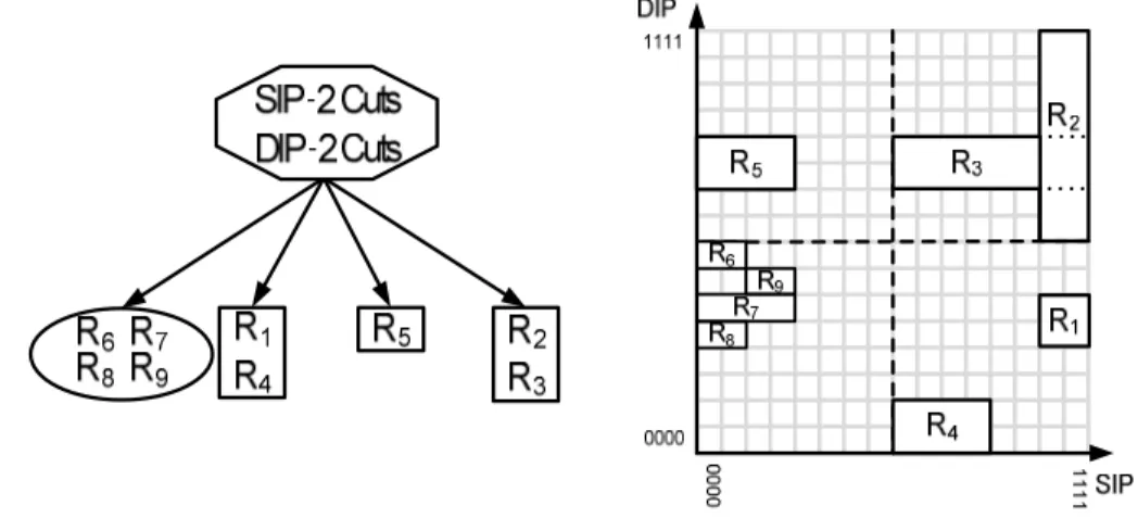
Fig. 2.3. HyperCuts decision tree (left) and its geometric representation (right).
number of rules limited by the binth value. Once a leaf node is reached, a short linear search of the rules contained within it is performed to find the matching rule. HiCuts uses heuristics to reduce memory usage, such as the merging of identical nodes to avoid replicated storage and the removal of rules from a leaf node that can never be matched as they are covered in that leaf node by a rule with a higher priority.
Multidimensional Cutting (HyperCuts)
HyperCuts by Singh et al [10] is a modification of the HiCuts algorithm that also allows incremental updates. The main difference between it and HiCuts is that it recursively cuts the hyperspace into sub-regions by performing cuts on multiple dimensions at a time. Fig. 2.3 shows an example of a decision tree built from the ruleset in Table 2.1. It also includes a geometric representation of the source and destination IP addresses, showing the cuts made to create the decision tree. The source and destination IP addresses are both cut in two, resulting in one empty node (represented by a circle) and three leaf nodes. All child nodes conform to the
binth value, meaning that no more cutting is required. HyperCuts acts like HiCuts if only one dimension is chosen for cutting. The algorithm also limits the number of cuts that can be performed to an internal or root node to prevent excess memory usage, using a set of rules and a user defined variable known as spfac. HyperCuts also takes advantage of extra heuristics that exploit the structure of the classifier such as region compaction, which allows for more efficient cutting of a dimension as it only cuts the region covered by the rules rather than the full region. It also pushes common rule subsets upwards to avoid the replicated storage
Fig. 2.4. Extended Grid-of-Tries with Path Compression.
of rules by storing rules common to all child nodes in their parent node. A packet is classified in the same manner as the HiCuts algorithm, with a packet traversing the decision tree by using the same cutting sequence on the header used to create the decision tree until a leaf node is found, where a linear search of the rules within it takes place.
Extended Grid-of-Tries with Path Compression (EGT-PC)
EGT-PC by Baboescu et al [15] is another decision tree-based algorithm that allows incremental updates. In EGT-PC a path compressed trie is first created from the prefixes in the ruleset’s first dimension. Each node in this trie, which represents a valid prefix P in the first dimension, will contain a pointer to another path compressed trie made up of all the prefixes from the second dimension whose first dimension prefix is equal to P. Each node in the second dimension trie corresponding to a valid prefix in this dimension will contain a list of all the rules that match the prefixes of the first and second dimension nodes. This means that a rule can only occur in one position. In order to avoid back tracking, all failure points in the second dimension tries contain a jump pointer, which points to the next possible second dimension trie that could contain a matching rule. Fig. 2.4 shows the search structure built from the rules in Table 2.1.
The search algorithm works by first performing a Longest Prefix Match (LPM) on the first dimension trie. The resulting pointer is then followed to a second dimension trie. A LPM is then carried out on this trie to find nodes containing matching rules. Each time there is a failure or the end of a second dimension trie is reached,ajump pointer is followed. This is continued until anode is reached
Fig. 2.5. Recursive Flow Classification search structure.
that contains no jump pointer. All matching rules along the way are recorded, with a small linear search of these rules carried out at the end.
Recursive Flow Classification (RFC)
RFC by Gupta and McKeown [12] is a decomposition-based algorithm that classifies packets at high throughput rates using lookup tables placed across multiple phases. It does this at the cost of a long pre-processing time when building these tables, high memory consumption and an inability to allow incremental ruleset updates. It uses the fields from a packet’s header as indexes to access direct lookup tables in the first phase. These lookup tables are built from the corresponding fields of the rules in the ruleset. The size of each lookup table in this phase will be 2n, where n is the number of bits in a given field. The source IP and destination IP address are usually split into 16-bit chunks to prevent their lookup tables having excessive memory consumption. This means that each IP address requires two lookup tables in the first phase, with the remaining fields requiring one each.
The lookup tables in the first phase are accessed in parallel, returning pre-processed eqIDs. These eqIDs represent and are smaller than the indexes used to access the lookup tables. The indexes for performing lookups on tables in the next phase are formed by combing the eqIDs from the previous phase. The final phase contains one lookup table, with the value returned from this being the matching rule number. This is possible because of the way that the lookup tables are constructed. Fig. 2.5 shows the configuration of the twelve lookup tables in the implementation used here and how they are spread across four phases.
Fig. 2.6. Tuple Space Search with Tuple Pruning.
Tuple Space Search (TSS) with Tuple Pruning
TSS by Srinivasan et al [16] is a hash-based algorithm that supports incremental updates. All rules are divided into groups called tuples, with rules that map to a particular tuple having the same prefix length for the source and destination IP addresses. Their source and destination port numbers will either be a wildcard or the same nesting level inside the port range. Protocol values will either be wildcard or a specific value. The nesting level of a port will help to distinguish the tuple group the rule belongs to but will not help to separate the rule from other rules within a tuple group. For this reason each port address will have a RangeId, which notes a port’s position inside its nesting level. A packet’s port number is usually converted to its RangeId using a 65KB direct lookup table.
A hash key is made for a tuple group by using its tuple specification e.g. (3, 1, 1, 2, 17) to pick out the appropriate bits from a packet’s source and destination IP address, RangeIds (found using the port numbers) and protocol number. All rules belonging to tuple T are stored in Hashtable (T). A probe of a tuple T is carried out using the hash key created, with only one memory access needed for each tuple to determine if it contains a matched rule. The algorithm is motivated by the fact that a linear search through all tuples will be smaller than a search through all rules. The number of tuples that need to be searched is further reduced through tuple pruning. Tuple pruning involves creating LPM tries, which are usually made from the source and destination IP addresses. Each node in a trie that represents a valid prefix will contain a bitmap, with each set bit in the bitmap indicating a particular