Development of Graphical User Interface by
Applying Philosophy of Use Case Maps
Ebitisam K. ELBERKAWI *, Mohamed M. ELAMMARI **
* Academy of Graduate Studies, Benghazi, Libya
[email protected]
**Faculty of Information Technology, Garyounis University, Benghazi, Libya
[email protected]
Abstract:Graphical User Interface (GUI) development is as important as other aspects and phases of programming, as GUI elements are typically the only means by which the user interacts with the program. Thus, even if the functionality of the application is perfectly executed, if its GUI is difficult to use, this can result in an implementation failure. In such cases, the user will switch to another application, which is easier and more flexible, even if its internal functionality is inferior. Therefore, the GUI must primarily be user-friendly, and must be built on strong foundations and pillars. This paper introduces an approach for designing GUI based on a model that offers visual description of high-level system logic—Use Case Maps (UCMs), which is utilized in three phases.
Keywords: Graphical User Interface, Use Case Maps.
1. Introduction
There is no doubt that the role played by the Graphical User Interface (GUI) in making systems more successful is very important. In practice, it is not uncommon for strong performance systems to fail at their implementation stage due to the shortcomings in their GUI. The GUI is the interface between the user and the system and thus plays the key role in the application acceptance. In short, although GUIs typically include less complex elements to develop, they are critical to the success of the system. Moreover, given that their acceptance relies on user preference, they are often the hardest part of the system to develop. Thus, GUI designers and programmers must achieve a high degree of cooperation in the design of GUI. Analysis and design phases are integral part of project life cycle and they must incorporate GUI from the inception. In addition, user input is essential aspect of GUI construction and design. This paper presents an approach to GUI design that is based on the primary phases of system development and supports the role of the user. Such approach increases the chance of cooperation between the GUI designer and programmer as well as ensures that the final product meets user requirements.
In this paper, we focus on the design of GUI through Use Case Maps (UCMs) as one of high-level models. The approach proposed in this paper is composed of three phases, starting from UCMs and ending in GUI: the first phase (Responsibility Analysis) produces a Responsibility Diagram (RD); second phase (GUI Design) produces GUI Design Tables (GUI_DT),
which contain all details of designing the GUI; and last phase (GUI Development) produces the GUI. The rest of the paper is organized as follows: Section 2 gives a summary of some pertinent literature, where key findings and comparisons of these works are discussed. Section 3 describes the three phases of our GUI design approach in more detail. Its implementation was further elaborated on through a case study in Section 4. Finally, Section 5 presents discussion, followed by the key conclusions and recommendation for future works.
2. Literature Review
Most of the extant studies related to our work focus on achieving GUI design using Unified Modeling Language (UML), as was done in works [4,5,7]. There is also some evidence [4,7] of a GUI design through Use Cases. Thus, it is worth to briefly elaborate on the role of Use Cases and system details they present, which is at the level of the system functions from viewpoint of external actors. On the other hand, work by Almendros-Jim´enez and Iribarne [7], focus has been made on the relation <include> without knowing the role of the relation <extends>, as each of these two relations has an important role in Use Case Model. Moreover, Pinheiro and Paton [5] focus on UI modeling by means of UML. Within this work, we have seen strong and weak aspects in the UML and have identified their respective roles in UI modeling. Same authors in [6] primarily focused on the aspects of GUI that are not covered by UML. Hence, they introduced additional notation when designing Interactive Applications. Thus all previous attempts to
des and aim thr hig Th of hig beh un pro Mo UC kn est cas wit dia un Mo dia can bet afo com bas UC eno a p in seq pat ma sho pat nec com A po pro end fel and res (e. rec of com Ind com Th beh sign a GUI h d, in general m of this w rough which gh-level mod he main adva GUI is bas gh-level de havior in o derstand way ovides wealth oreover, an CM and man own modeli tablished. UC se diagrams thout any de agrams, whi derstanding oreover, UC agrams and s n be perceive tween requ orementioned mpetence of sis from whi CMs are p ough inform person to visu Figure 1) quences in t ths, which ar ay have man ows one). A ths is und cessarily b mponents. Fi filled circle int where s ogressing alo d-point—the lt. Thus, path d end-poin sponsibilities g., r1, r2 ctangular box the system ( mponents p dividual pat mponents ma he basic a havior can b have both ad l, most depe work is to h GUI is de del . antage for se sed on its m sign view, one view in y, in addition h of informa important a ny kinds of d ing languag CM acts as a s (UCDs), w etails (Black ich describe the system CM provides structural dia ed as Gray-B uirements d features f UCM, it h ich the GUI w
recise struc mation in high ualize system provide a the system re known as ny paths (fo Although the derstood by be the cas igure 1: Exam e indicates a stimuli occu ong the path. e point whe hs trace cau nts. The c s, indicated b and r3). P xes represen (e.g., C1, C2 participate ths may cro ay have man assumption e represented dvantages an end on Use design a g eveloped, us electing UCM many advan combining n a graphica n to its comp ation [1, 2]. and useful l diagrams for ges, namely an intermedi which descr k-Box), and e more det very diffic s a link betw agram. In th Box [3], as it and desig and sup has been se will be devel ctural entitie hly condense m behavior. U high-level as a whole, scenarios. In r simplicity, e causality e y humans, se for ind mple of a UC a start-point ur, causing . Similarly, a re the effec sal sequence causal sequ by named po Paths are su nting operatio 2 and C3), t in the cau oss many c ny paths cros is that st d in a simple nd disadvant Cases. Thus general appr sing UCMs M for the de ntages, inclu g structure
al, and easy pact form, w linkage betw r one of the m UML, can ary between ribe the sy other behav tails that m cult (Glass-B ween behav his respect, U t bridges the gn. Based pport for lected to be loped. es that con ed form to en UCMs (as sh view of ca in the form n general, UC , the figure expressed by this may dividual sy CM. t of a path— activity to a bar indicate ct of stimuli es between s uences con oints along p uperimposed onal compon o indicate w usal sequen components sing them. timulus-resp e way with p tages s, the roach as a esign uding and y to which ween most n be n Use ystem vioral make Box). vioral UCM e gap on the e the ntain nable hown ausal m of CMs only y the not stem —the start es an i are start- nnect paths d on nents where nces. and ponse paths. Th sys pat com
3.
Th pha wh inv con pha the com ele Bu cla we im G3.1
3.1
A the int UC his is a very stems with w th-centric sy mponent-cenThe Appr
he approach ases. In the here the RD volves apply ntents of GU ase, content eir correspo mplete GUI ements of G utton, Textbo arify the app ell as the plementation F T Phase Name Responsibility Analysis GUI Design GUI Development1 First Pha
1.1 Rules
number of ru e importanc teraction with CM. In this c common ch which we are ystem view, ntric view.roach
proposed in first phase, r will be gen ying rules to UI_DT in thei ts of the GU nding GUI I with all o GUI covered ox, Label, and proach phase profession n of each pha Figure 2: The A Table 1: The Ap Availability o UCM Of the system RD GUI_ DTse: Respon
ules have be e of input, h the user fo ontext, the re haracteristic e concerned rather than this paper c rules are app nerated. The o RD, where ir different k UI_DT are elements, of its eleme d in our w d List. Figur es and their nal in ch ase. Approach Phase Approach Phases of Descriptio m Apply rules UCM Apply rules to Convert tab into design ofnsibility An
een proposed , processing or each respo responsibility of the types and results i a conventio comprises th plied to UCM e second ph e we will h kinds. In the converted i resulting in ents. Thus, work are Fo re 2 and Tabl relationship, harge for s. s. on Result s to RD o RD GUI_ DT bles f GUI GUInalysis
d, depending g, output, a onsibility of y refers to tas s of in a onal hree Ms, hase ave last into n a the rm, le 1 , as the T g on and the sks,actions or functions to be performed. This distribution of responsibilities was the basis of construction of most rules presented below, with the aim to achieve the desired results through application.
Rule 1
A component in UCM is a form, where this component contains at least one responsibility that requires GUI elements.
Rule 2
Sequence of forms is based on the sequence of components in UCM.
Rule3
A responsibility will be considered if it requires GUI elements for:
• Obtaining required input for implementing its work
• Executing its work
• Showing the output resulting from implementing its work
• Interacting with the user to show him a message
Rule 4
A responsibility that needs GUI elements for its input must have:
• (X) text boxes
• (X) labels
• (2)buttons (‘Ok’ and ‘Cancel’ button)
where X is a number dependent on the number of data inputs.
Rule 5
A responsibility that requires GUI elements for executing its work must have:
• (1) button (Execute Button)
Rule 6
A responsibility that requires GUI elements to display its output must have:
• (Y) lists
• (Y) labels
where Y is a number dependent on the number of resulting outputs.
Rule 7
A responsibility that needs GUI elements for interaction with the user is a separate form containing a message with a button the function of which is to close the display form.
Rule 8
If a responsibility requires a sub-input based on essential input (Multi-input), then, an independent form is generated to receive additional input using the same input rules as defined in Rule 4.
Rule 9
If a responsibility requires a sub-output based on essential output (Multi-output), then, an independent form is generated to show additional output using the same output rules as described in Rule 6.
Rule 10
The main form of the system is generated based on forms obtained from above-mentioned rules, i.e. using (Bottom_Up) approach.
Rule 11
For each main form, there is an ‘Exit’ button and a ‘Return’ button for each sub-form.
Rule 12
Applications of specific graphical user interface [13], such as ATM system, require no main form and no ‘Exit’ and ‘Return’ buttons. This type of systems has relay forms with no need to return to the main form to select a specific form. Accordingly, a ‘Welcome’ form is displayed in the beginning of user interaction, which is followed by the remaining forms.
Rule 13
Cases that require more than one scenario represented by static stub notation using (Or) relation are translated into a number of buttons equal to the number of scenarios, where each button may cause moving to the form of the chosen scenario.
3.2 Second Phase: GUI Design
3.2.1 Responsibility Diagram (RD)
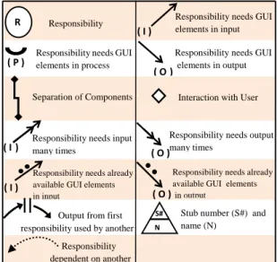
RD is a diagram the notation of which has been built and especially designed to show what may result from the process of applying rules to UCMs. Table 2 explains RD notation.
Table 2: RD Notation.
R Responsibility Responsibility needs GUI elements in process
( P )
Responsibility needs GUI elements in input
( I )
Responsibility needs GUI elements in output
Interaction with User Separation of Components
Responsibility needs input many times
( I )
Responsibility needs output many times
Output from first responsibility used by another
Responsibility dependent on another
Stub number (S#) and name (N)
N S#
( O ) ( O)
Responsibility needs already available GUI elements in input
Responsibility needs already available GUI elements
in output
( O ) ( I )
3.3 Third Phase: GUI Development
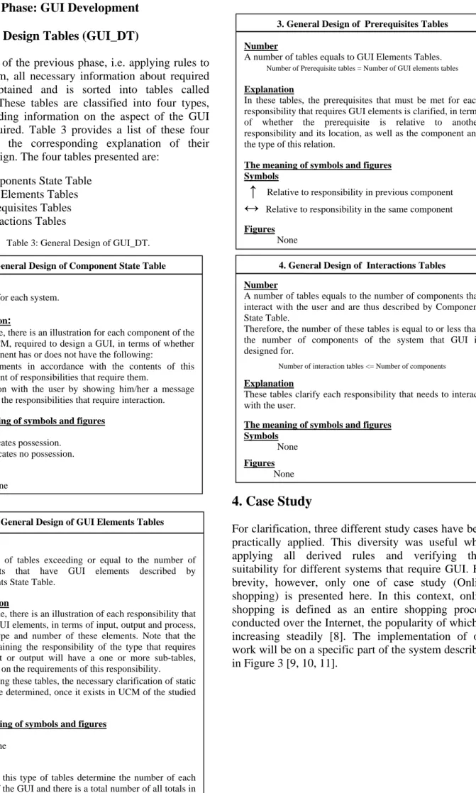
3.3.1 GUI Design Tables (GUI_DT)
As a result of the previous phase, i.e. applying rules to RD diagram, all necessary information about required GUI is obtained and is sorted into tables called GUI_DT. These tables are classified into four types, each providing information on the aspect of the GUI design required. Table 3 provides a list of these four tables and the corresponding explanation of their general design. The four tables presented are:
1. Components State Table 2. GUI Elements Tables 3. Prerequisites Tables 4. Interactions Tables
Table 3: General Design of GUI_DT.
4. Case Study
For clarification, three different study cases have been practically applied. This diversity was useful when applying all derived rules and verifying their suitability for different systems that require GUI. For brevity, however, only one of case study (Online shopping) is presented here. In this context, online shopping is defined as an entire shopping process conducted over the Internet, the popularity of which is increasing steadily [8]. The implementation of our work will be on a specific part of the system described in Figure 3 [9, 10, 11].
1. General Design of Component State Table
Number:
One table for each system. Explanation:
In this table, there is an illustration for each component of the system UCM, required to design a GUI, in terms of whether this component has or does not have the following:
•GUI elements in accordance with the contents of this
component of responsibilities that require them.
•Interaction with the user by showing him/her a message
based on the responsibilities that require interaction. The meaning of symbols and figures
Symbols
X Indicates possession. - Indicates no possession. Figures
None
3. General Design of PrerequisitesTables Number
A number of tables equals to GUI Elements Tables. Number of Prerequisite tables = Number of GUI elements tables Explanation
In these tables, the prerequisites that must be met for each responsibility that requires GUI elements is clarified, in terms of whether the prerequisite is relative to another responsibility and its location, as well as the component and the type of this relation.
The meaning of symbols and figures Symbols
↑
Relative to responsibility in previous component
↔
Relative to responsibility in the same component
Figures
None
4. General Design of InteractionsTables Number
A number of tables equals to the number of components that interact with the user and are thus described by Component State Table.
Therefore, the number of these tables is equal to or less than the number of components of the system that GUI is designed for.
Number of interaction tables <= Number of components Explanation
These tables clarify each responsibility that needs to interact with the user.
The meaning of symbols and figures Symbols
None
Figures
None
2. General Design of GUI Elements Tables
Number
A number of tables exceeding or equal to the number of components that have GUI elements described by Components State Table.
Explanation
In this table, there is an illustration of each responsibility that requires GUI elements, in terms of input, output and process, and the type and number of these elements. Note that the table containing the responsibility of the type that requires multi-input or output will have a one or more sub-tables, depending on the requirements of this responsibility.
Note:Using these tables, the necessary clarification of static stub can be determined, once it exists in UCM of the studied system.
The meaning of symbols and figures Symbols
None
Figures
Figures of this type of tables determine the number of each element of the GUI and there is a total number of all totals in the last row of the tables.
4.1
pro GU 4 s Cu F
1 Practical
(Resp
In this phas ovided for th UI by applyin shows a UCM Figur Search Add to C ustomer Catal Search igure 3: OnlineApplicatio
ponsibility
se, as already he system for ng rules to U M of Online re 4: UCM of on G Re A Re CCart / Remove from cart
Add to logue [Found] [Not Found] e Shopping Syst
on of First P
y Analysis)
y explained, r which we n UCM to obta Shopping Sy nline shopping Co Graphical Elem Responsibility Search Total Graphical Element esponsibility Ty Add to cart P O emove from cart P Check Out P Cont Check Out If Car Shopping C cart Remove From cart Che tem.Phase
a UCM mus need to devel in an RD. Fi ystem. system. Table 4: GUI_D Co I. omponent Name Catalogue Shopping Cart II. G II.1 Com ment Label Type I 1 O 1 2 II.2 Compo t Label ype P - 1 O 1 -P - 1 P - 1 tinue Shopping rt is Nonempty Cart ck Out [Nonempty] [Empty] st be lop a igure At UC as cla4.2
In pre of yie DT of online sh omponents State GUI Elements x x GUI Elements T mponent name : C Button 2 • Ok, Cancel - -2 onent name : Sh Button • Execute Button -• Execute Button • Execute Button the end of CM of Onlin shown in arified. Figure
2 Practical
this phase, evious phase this phase, eld four table
hopping system Table Interact with U x x ables Catalogue Text List 1 -- 1 1 1 opping Cart Text List - -- 1 - -- -Search ( I ) ( O ) Catalogue f this phase, ne Shopping Figure 5, u e 5: RD of Onli
Applicatio
(GUI De
rules are ap e, yielding da the GUI_DT e types, as de m. User Description Search Results 6 t Descriptio Add to cart Shopping ca Remove from Check Out ( P ) ( I ) Add to cart and applyin System, an R using the n ine Shopping Son of Secon
esign)
pplied to RD ata for GUI_T (shown in escribed abov on rt art cart t Shopping Ca Remo c ( O ) ( P ( I ) ng the rules RD is obtain otation alrea ystem.
d Phase
D as a result _DT. At the e n Table 4) w ve. art ovefromcart Check Out
P ) ( O ) ( P ) s to ned, ady t of end will t
4.3
Th des bel I. M II.
3 Practical
(GU
he above GU sign the GU low (Figure Main Form Catalogue ONLINE SHOPPIN Catalogue Search Results Respo Add Remo c ChecApplicatio
UI Develop
UI_DT provid UI and its e 6). NG SYSTEM Catalogue Shopping Cart Exit Total Responsibilit Search Pre onsibility Ava items add to cart Car no (Item ove from cart ck Out Re Respon Checon of Third
ment)
de all inform elements. Th t Ok Cancel Return 1 III. III.1 Com Prerequisit ty III.2 Compo erequisite Re ilability of that can be ded to cart Res Re rt must be onempty ms added to cart ) Res Ad -IV. IV.1 Com esponsibility Search I Compo IV.2 nsibility ck Out The us
d Phase
mation neede he design sh 3 Prerequisites Ta mponent name : Type of Pre te -onent name : Sh Type of Prereelation with another
Type relat Outp esponsibility name Search
elation with another
Type relat Outp esponsibility name dd to cart -. Interactions Ta mponent name : Description
If item is not found a
onent name : Sh
Description
ser cannot continue be
ed to hown III. IV. - 1 ables Catalogue S requisite hopping Cart equisite r Responsibility Location ↑ e of tion put r Responsibility Location ↔ e of tion put ables Catalogue n Of Interact as a result of searchin hopping Cart n Of Interact
ecause shopping cart
Shopping Cart Interaction For Shopping Cart Shopping Cart Ok
Item not fou
Attention
5
Suggesting
-Suggesting
As a result of such link t responsibility in an component by the outp must be provided betwe
two forms
(Thus, we propose merg forms into one)
-g is empty Form rms R Ca Atten und g to another nother put, a link ween these rging both ) Add To Cart
Remove From Cart Check Out Return Ok annot continue … Ca is empty ntion rt
Ac Ta for the
5.
5.1
Giv des bet app com An De to app By stu con ter bas a des enr ana dev pro coo and wh vie5.2
sm tha Fir not Sta Th esp GU fur Sec tha ccording to th ables, the tworm. This pro e programme
Figure 6: D
Conclusio
1 Conclusio
ven the cru sign and app tween the sy proach to de mprises thr nalysis pha evelopment p the rules t proach, the y obtaining G udy and com
nfirmed that rms of GUI sic foundatio GUI throug signing syst richment of alysis and d velopment. ovides objec operation be d contribute hilst incorpor ews, but also
2 Future St
We rec mall range of at may be con rst: In our w tation of UC atic stub as a herefore, look pecially Dyn UI will be rther on. cond: There at could be a Shopping Cart Shopping Cart Results Search he suggestio o forms will posal is put er. Design of GUIoons and Re
ons
ucial role of plication, as t ystem and th evelop GUI ree consecut ase, GUI phase. Each p that guidefirst and the GUI design mparing it wit t it satisfied I elements on of our wo gh primary tems, thus o f this impor design of sy Moreover, t ctive and eas etween GUI d
in building G rating not on o the user req
tudies
cognize that f application nsidered in f work, we d CM. On the an advanced king at the re namic stub, t very valuab are many is a subject of f on mentioned be merged in forward by of Online Shopecommend
f GUI in su the only mea he user, we h from UCMs tive phases— Design ph phase is cond the implem e second phafor the sys th the presen the needs o gained thro ork. This enab
phases of our paper co rtant aspect ystems in G the approach sy to use too designer and GUI applicat nly design an quirements. our work w s and identi future studies ealt with m e other hand classified n est of the ad to know its r ble in studyi sues related future studie Add To Cart
Remove From Cart Check Out Return Ok Cancel d in Prerequi nto the follow
GUI Design ping System.
dations
uccessful sy ans of interac have propose s. This appr —Responsib ase, and ducted accor entation of ase in partic stem of the nted scenario of this system ough UCM— bled us to de f analyzing ontributes to i.e. the rol GUI design h presented ols that stimu d the program tion compon nd programm as delimited fy several is s. most of the b d, we mentio otation of U dvanced nota role in desig ing these is to GUI elem es, such as R isites wing ner to stem ction ed an roach bility GUI rding this cular. case o, we m in —the esign and o the le of and here ulate mmer nents, ming d to a ssues basic oned UCM. ation, gning ssues ments Radio Bu int im app Fin on issRe
[1] [2] [3] [4] [5] [6] [7] We [8] [9] [10 [11utton and Che to the GU provements plicability of nally: The ap different sy ue and work