Seismic Failure Mode Simulation for Low-Ductile R.C.
Frame Structures
Peizhou Zhang, Shuang Hou & Jinping Ou
School of Civil Engineering, Dalian University of Technology, Dalian, China
SUMMARY:
Recently, several earthquakes struck China, and the survey shows that R.C. frames designed according to the early seismic codes suffer severer damage than buildings built according to current code. Older R.C. frames have poor ductility, shown as shear failure and bar-slip behavior in beam-column joints. In this paper, firstly the causes of the low ductility of such frames are summarized based on Wenchuan earthquake reconnaissance and Chinese seismic building codes. Secondly, a modeling method for this type of structure is developed through OpenSees, and validated by comparing with the results of two R.C. frame tests. In this method, a simplified joint model proposed by the authors is presented, which makes it possible to take account the shear failure of joints and bar-slippage behavior during modeling the whole structure for seismic analysis. Then a R.C. frame with joints damaged in Wenchuan Earthquake is analysed with the modeling method mentioned considering its low ductility. The results agree well with the typical earthquake damage observed in Wenchuan earthquake. At last, the seismic failure modes of this structure are discussed.
Keywords: low-ductile R.C. frame, failure mode, shear deformation, bar-slip
1. INTRODUCTION
Recently, several earthquakes struck China. According to the field earthquake reconnaissance from Tangshan and Wenchuan earthquake, it can be concluded that there are less R.C frames than masonries before Tangshan earthquake. After Tangshan earthquake, ring beams and constructional columns have been widely utilized in masonry and perform well during later earthquakes. In the past 30 years, Chinese Code for Seismic Design of Buildings was updated several times and more R.C frame buildings prevail. As observed from reconnaissance structures built before the year 2000 suffer severer damage (Lin et al, 2009) and the main damages of R.C frames are the shear failure of columns and joint cores. Such R.C frames are termed as low-ductile R.C frames.
Many countries such as U.S., Japan and New Zealand research on reconnaissance have been
undertaking while this kind of research has not been reported in China. Although many R.C frames are relatively new, the poor ductility is still a serious problem. So it is important to evaluate the seismic performance of this kind of structures based on the Chinese seismic building codes.
2. CAUSES OF THE LOW-DUCTILITY BASED ON SEISMIC CODES
In China, systematic study of seismic performance dates back to 1950s. There are three stages in the development of Chinese Code for Seismic Design of Buildings. By comparison of concepts and structural measures in different codes, seismic code published in1978 (“Code 78” for short) mainly calculated the structural component strength under common earthquakes without seismic prevention principle and ductile design method, which leads to weakness in structural measures. According to study of codes in different periods and reconnaissance of Wenchuan earthquake, the causes of low ductility of R.C. frames built during 1970-1980 can be concluded as followed:
1) Strength of concrete is very low, usually No. 200 (TJ10-74, 1974) about 17.43 MPa, and the concrete performs poor ductility;
2) R.C. frames designed according to “Code 74” and “Code 78” are low in ratio of stirrups due to the small diameter and large spacing, which most likely cause shear failure of joint cores;
3) Plain round bars with corrosion through joints can lead to severe bar-slip which will reduce the energy dissipation capacity of the structure.
According to the analysis above, shear failure of joints and bond-slip behavior of beam steels are mainly discussed by modeling in this paper.
3. STUDY ON EXPLICIT MACROSCOPIC JOINT MODELS
Due to different levels of seismic codes in different periods, existing and newly-built structures differ in seismic failure modes. Shear failure usually could be avoided in newly-built structures by common design philosophy such as “strong column and weak beam”, “strong shear and weak bending” and “strong joint and weak member”, but it is common in existing structures. At present, most engineering softwares for design and analysis can barely take shear failure of joints and bar-slip behavior into consideration and therefore the current modeling methods are not suitable for such structures. So a new modeling method for this type of structure is developed on the OpenSees platform considering shear deformation of joints and bar-slip behaviour to evaluate the low ductility of such structures. 3.1. Modeling Method in the Joint Region
3.1.1. Literature review of previous macroscopic joint models
On summarizing the references, Fu Jianping had conducted a full analysis on force transmission characteristics of joints and pointed out that there is confined mechanism besides diagonal compressive strut and truss mechanism. N-Mitra concludes some modeling methods of joints, and puts them into implicit and explicit models. Implicit models consider the joint region indirectly by using nonlinear springs or plastic-hinges or both at the member ends to model the shear deformation of joints and bar-slip behavior. Such models are useful to determine the overall influence of nonlinear joint action on structural response. However, it is difficult to calibrate since the joint behavior is separately considered between the adjacent beams and columns. Such typical joint models are shown in literatures (El-Metwally et al, 1988; Alath et al, 1995; Uma et al, 1996). Explicit models which consider an explicit representation of the joint region are easy to be calibrated, which satisfy joint kinematics and also can be used as separate macroscopic elements in frame models composed of line elements. Several representative models are shown in literatures (Fleury et al, 2000; Altoontash et al, 2003; Lowes et al 2000; Mitra et al, 2007). Among all the methods, Mitra-Lowes model put forward by Mitra and Lowes in 2007 is relatively considerate and easy to be calibrated. The model is called as BeamColumnJoint (BCJoint for short) and widely used in OpenSees.
3.1.2. Joint model in this paper 1) BCJoint
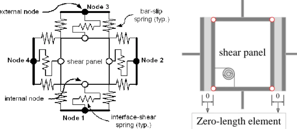
BCJoint model was first proposed by Lowes and Altoontash in 2004, which consists of a four-node, twelve degree-of-freedom element to model the response of R.C. beam-column joints in 2D structural analysis. The joint element represents a super-element comprising a shear-panel component that simulates strength and stiffness loss due to failure of the joint core, eight bar-slip springs that simulate stiffness and strength loss due to anchorage-zone damage, and four interface-shear springs to consider crack opening as shown in Fig. 3.1. To make it easier for using, Mitra and Lowes then modified the model on the basis of 50 different joints in 2007. However, there are still many problems of BCJoint model, such as poor performance of convergence, inconvenient calibration of bar-slip model, especially in dynamic analysis.
2) Proposed joint model (SimpleJoint for short)
A simplified model is proposed based on Mitra-Lowes joint model in OpenSees to consider each component of joints in detail, as shown in Fig. 3.2. Compared with the BCJoint model, the
SimpleJoint model keeps the shear panel component but replaces the bar-slip springs by zero-length elements at the beam ends. In the zero-length elements, the stress-slip relationship of steel instead of stress-strain relationship is applied to simulate the bar-slippage through joints. Furthermore, the SimpleJoint model is flexible enough during calibrating bar-slip models and can consider the influence of steel corrosion on the deterioration of bond capacity. The most important is that the proposed model can be applied in dynamic analysis to study the seismic behavior of low-ductile structures.
Figure 3.1. BCJoint model
0 0
shear panel
Zero-length element Figure 3.2. SimpleJoint model 3.2. Calibration Method in the Joint Region
3.2.1. Calibration of shear deformation in the joint core
The parameters of the joint model comprise three aspects: shear deformation in the joint core, beam steel stress-slip relationship through the joint, as well as shear hinge at the joint perimeter. In this part, we only study shear stress-strain relations in the joint core. Three theories are introduced including modified compression field theory (MCFT) (Vecchio et al, 1986), diagonal compression strut model (DCSM), and strut-and-tie model (STM) (Song, 2009). MCFT is used for defining parameter of shear stress-strain in narrow limitation (Wu, 2007); DCSM is based on the assumption that shear force is transferred only through a diagonal compression strut within limited width in the joint core, but it can’t consider the influence of truss mechanism and different ratio of stirrups on mechanic behavior of the joint, especially with low stirrup ratio (Song, 2009). Based on the STM theory, Song Mengchao develops a simplified STM method by adding the substrut to consider the direct shear effect of stirrups, which simulates truss mechanism effectively. But this theory ignores the shear effect of longitudinal reinforcement. This paper mainly uses DCSM and STM to define the parameters of the joint core. 3.2.2. Calibration of bar-slip model in the joint region
According to Xu Youlin’s research on bond-slip distribution with the varying anchor length and the results of the Fu Jianping’ s joint test, it can be concluded that the whole strain of beam steel through the joint is basically a linear change. Sometimes when the shear-compression ratio and axial-
compression ratio are large, the distribution of tension and compression doesn’t change with the development of the plasticity. So the distribution of bond stress and bar stress in the joint can be assumed as shown in Fig. 3.3. Then we can obtain the steel stress-slip relationship by integrating, and replace the steel stress-slip relationship in the zero-length element at the joint perimeter.
3.3. Validation of the Modeling Method
3.3.1. Validation of the joint modeling method
1) Validation of parameter defining method in the joint core
The test by Kusuhara and Azukawa in 2004 has a typical stirrup ratio in joint. The DSCM and STM theory are applied to define parameters of shear stress-strain relations respectively, and the hysteretic
curve is produced by using BCJoint model as shown in Fig. 3.4. fs < fy fs > fy fsAb τE τY fy Bond Stress τ Bar Stress fs
Figure 3.3. Distribution of steel stress and bond stress in the joint panel
-100 -50 0 50 100 -100 -50 0 50 100 Displacement(mm) F or ce (K N ) DSCM STM TestResult
Figure 3.4. Hysteretic curves of Kusuhara & Azukawa joint
The figure shows that both STM and DCSM theories are effective to simulate the behavior of joint, and STM’s result is more accurate, which is closer to the experimental result with maximum load 92KN.
2) Validation of modeling method for interior and exterior joints
Tang Jiuru had conducted a series of exterior joint tests. Test H-1 has no stirrup in the joint, which represents the existing R.C. frame joint; test H-2 has some stirrups in the joint, which represents newly-built ones. Fig. 3.5 and Fig. 3.6 show the analytical results of H-1 and H-2 by BCJoint model and SimpleJoint model respectively. To H-1, the capacity is 100KN in test, while the numerical result is 105KN. To H-2, the capacity119KN in test agrees well with the STM result 120KN. And for the hysteretic behavior, there are some differences between macro-joint elements and test results, with the error acceptable. Tang’s numerical results show that the STM theory is suitable to determine the parameters of exterior joints with various types of stirrup layout.
-40 -20 0 20 40 -100 -50 0 50 100 Displacement(mm) F or ce (K N ) STM-BCJoint TestResult STM-SimpleJ
Figure 3.5. Hysteretic curves of H-1 joint
-40 -20 0 20 40 -100 -50 0 50 100 Displacement(mm) F or ce (K N ) STM-BCJoint TestResult STM-SimpleJ
Figure 3.6. Hysteretic curves of H-2 joint Fig. 3.7 shows analytical results of the interior joint experiment with slabs, which was tested by Architectural Society of China Earthquake Disaster Prevention Branch in 2011. The figure shows that the result of SimpleJoint is closer than BCJoint to the test result.
The validations at component level shows that it is feasible to simulate joints with SimpleJoint model based on STM theory.
-100 -50 0 50 100 -30 -20 -10 0 10 20 30 Displacement(mm) F or ce (K N ) STM-SimpleJ TestResult -100 -50 0 50 100 -30 -20 -10 0 10 20 30 Displacement(mm) F or ce (K N ) STM-BCJoint TestResult
Figure 3.7. Hysteretic curves of analytical model and experiment 3.3.2. Validation of modeling method for R.C. frames
1) Simulation of the R.C. frame designed according to "Code 78"
The R.C. frame used in this paper has been designed by Xu Yunfei in 1986 according to “Code 78”. The frame was tested under cyclic loading, and its details can be obtained from Xu’ paper. It is analyzed in OpenSees with two modeling methods: without joints (Default) and with joints
(SimpleJoint).The load-displacement hysteretic curves are shown in Fig. 3.8. By comparison it can be found that the analysis result of the model using SimpleJoint is very close to experiment result.
-100 0 100 200 -200 -150 -100 -50 0 50 100 150 200 Displacement(mm) L at er al F or ce (K N ) SimpleJoint TestResult -200 -100 0 100 200 -200 -150 -100 -50 0 50 100 150 200 Displacement(mm) L at er al F or ce (K N ) Default TestResult
Figure 3.8. Hysteretic curves of the model with SimpleJoint and experiment 2) Simulation of the R.C. frame designed according to "Code 2001"
-200 -100 0 100 200 -150 -100 -50 0 50 100 150 Displacement(mm) L at er al F or ce (K N ) SimpleJoint TestResult -200 -100 0 100 200 -150 -100 -50 0 50 100 150 Displacement(mm) L at er al F or ce (K N ) Default TestResult
Figure 3.9. Hysteretic curves of the model SimpleJoint and experiment
To investigate the application of the method in analyzing R.C. frame structures with slabs, a six-story frame tested by Architectural Society of China Earthquake Disaster Prevention Branch in 2011 is analyzed with the same modeling method mentioned above. The load-displacement hysteretic curves are shown in Fig. 3.9, and its design details can be downloaded from the website:
www.collapse-prevention.net. The figure shows that the analysis result using SimpleJoint model is very close to the experiment result.
From the analysis results above, it can be concluded that the overall structural modeling method proposed in this paper can simulate the real behavior of structures and can be used for evaluating seismic performance of low-ductile R.C. frame structures.
4. STUDY ON SEISMIC PERFORMANCE OF TYPICAL LOW-DUCTILE R.C. FRAME STRUCTURE
4.1. Description of the R.C. frame structure in Dujiangyan city
The four-story building mainly for residential use is located in the downtown of Dujiangyan city in Sichuan. The first story is 5.1 meters high, with precast R.C. slab; other typical stories are 3.6 meters high, with precast R.C. slabs; the slope roof is 2.87 meters high, with cast-in-place R.C. slab. Other design details are as follows: the significance grade for seismic design of the frame is three; average concrete strength is 26.4 MPa; stirrups and longitudinal reinforcements are HPB235 and HRB335 respectively. The structure suffers severe damage in Wenchuan earthquake of May 12, 2008. According to the survey, beam-column joints of the structure with low ratio of stirrups suffer severe damage, showing remarkable low ductility of the structure. The plan and elevation of the structure is shown in Fig. 4.1, where the frame of shading is applied to study the seismic failure mode.
Figure 4.1. Plan and elevation of the structure 4.2. Modeling of R.C. frame 0 0.005 0.01 0.015 0.02 0 1 2 3 4 5 6 7 Strain (rad) S tr es s( M P a) ExJoint of 1st InJoint of 1st ExJoint of others InJoint of others
Figure 4.2. Shear stress-strain of joints
-10 0 10 20 30 40 50 -500 -300 -100 100 300 500 Slip(mm) S tr es s( M P a)
Figure 4.3. Typical stress-slip of beam steels Based on the modeling method mentioned above, the numerical model is formed in OpenSees
considering the shear failure of joints and bar-slippage through joints. The shear stress-strain relations of joints are defined by STM method, and the typical stress-slip relation of beam steels is calculated from the method shown in Fig. 3.3, both relationships are shown in Fig. 4.2 and Fig. 4.3.
4.3.1. Selection of earthquake ground motions
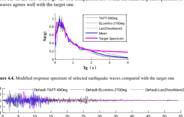
According to the current Chinese Code for Seismic Design of Buildings, the design seismic intensity of Dujiangyan city is 8 degree with ground motion of 200gal, seismic design group is II, and site classification is II. Based on above all, two earthquake records TAFT-690Deg and ElCentro-270Deg as well as an artificial wave LanZhou-2 are chosen, and modified with SeismoMatch to fit the code response spectrum as shown in Fig. 4.4, and then applied to the model as input ground motions. The acceleration curves are shown in Fig. 4.5. The comparison shows that the mean response spectrum of selected waves agrees well with the target one.
0 1 2 3 4 0 0.2 0.4 0.6 0.8 1 Tg(s) S a( g) TAFT-69Deg ELcentro-270Deg LanZhouWave2 Mean Target Spectrum
Figure 4.4. Modified response spectrum of selected earthquake waves compared with the target one
0 5 10 15 20 25 30 35 40 45 50 55 -0.4 -0.2 0 0.2 0.4 Time(s) A cc .( g )
Default-TAFT-69Deg Default-ELcentro-270Deg Default-LanZhouWave2
Figure 4.5. Modified time-acceleration curves of selected seismic waves 4.3.2. Study on earthquake failure modes
Three selected waves are applied to do nonlinear time-history analyses with Rayleigh damping, and damping ratio is 0.05 as recommended by Chinese Code for Seismic Design of Buildings. The first four order periods before and after earthquakes are shown in table 4.1.
Table 4.1. The first four order periods before and after earthquakes
Type of Model SimpleJoint Model (unit:s) Default Model (unit:s)
Order of Mode 1st 2nd 3rd 4th 1st 2nd 3rd 4th
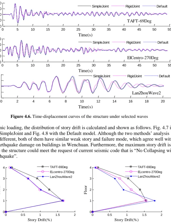
Before EQ 1.337 0.344 0.144 0.072 1.337 0.344 0.144 0.072 TAFT-69Deg 1.555 0.381 0.151 0.074 1.538 0.436 0.187 0.093 ElCentro-690Deg 1.531 0.377 0.150 0.074 1.556 0.440 0.189 0.093 LanZhouWave2 1.543 0.379 0.150 0.073 1.570 0.446 0.188 0.093 Three modeling methods namely model with joint panel and bar-slip (SimpleJoint), model with rigidity joint panel (RigidJoint), and model without joint panel and bar-slip (Default) are adopted to analyse the earthquake response of structure. Displacements at the top of the structure under selected earthquake ground motions are shown in Fig. 4.6 and it’s obvious that the results with RigidJoint are very different from other two methods. Displacement curves using SimpleJoint and Default model are different, but very close.
0 5 10 15 20 25 30 35 40 45 50 55 -180 -90 0 90 180 Time(s) D is p .( mm ) TAFT-69Deg
SimpleJoint RigidJoint Default
0 5 10 15 20 25 30 35 40 45 50 55 -180 -90 0 90 180 Time(s) D is p .( mm ) ElCentro-270Deg
SimpleJoint RigidJoint Default
0 2 4 6 8 10 12 14 16 18 20 -180 -90 0 90 180 Time(s) D is p .( mm ) LanZhouWave2
SimpleJoint RigidJoint Default
Figure 4.6. Time-displacement curves of the structure under selected waves
Under seismic loading, the distribution of story drift is calculated and shown as follows. Fig. 4.7 is the result with SimpleJoint and Fig. 4.8 with the Default model. Although the two methods’ analysis results are different, both of them have similar weak story and failure mode, which agree well with the observed earthquake damage on buildings in Wenchuan. Furthermore, the maximum story drift is less than 2%, so the structure could meet the request of current seismic code that is “No Collapsing with Strong Earthquake”. 0 0.5 1 1.5 2 0 1 2 3 4 Story Drift(%) F loor TAFT-69Deg ELcentro-270Deg LanZhouWave2
Figure 4.7. Distribution of maximum story drift with SimpleJoint
0 0.5 1 1.5 2 0 1 2 3 4 Story Drift(%) F loor TAFT-69Deg ELcentro-270Deg LanZhouWave2
Figure 4.8. Distribution of maximum story drift with Default modeling method
By analysing the global information of structure above, it is known that the results of models with or without consideration of joint are similar, without remarkable sign of low ductility. However, ductility of structure does not have great impact on capacity and failure mode of the overall structure, but on the ability of energy dissipation and the order of occurrence of plastic hinges. The following figures (Fig. 4.9) are the distribution of plastic hinges of the structure considering and not considering joints under selected waves, where big red spots mean that both positive and negative plastic hinges are formed, and small spots mean that only one of them are formed. Different slip value of rebar occur in different stories, with maximum value 0.15mm, and instead of shear failure, large shear deformation occurs in joint cores.
TAFT_Default El-centro_Default LanZhouWave2_Default
TAFT_SimpleJoint El-centro_ SimpleJoint LanZhouWave2_ SimpleJoint Figure 4.9. Failure modes of structure with two modeling methods under selected waves
From Fig. 4.9, we can see that the distribution of plastic hinges has the same rule with or without joint model, which is at the ends of all columns in first story and interior columns in other stories. But there is still difference of the amount of plastic hinges at member ends. When applying the SimpleJoint model, the plastic hinges are fewer because the shear failure and bar-slip in the joints take over the major plastic deformations. If the joint failure is prior to the members, beams and columns would be protected to some extent, as the experiment results from Yavari. When shear failure and bar-slip in the joints appear, the ductility and the ability of energy dissipation of the structure will be reduced, and the collapses caused by joint failure are tend to happen, as some real damage in Wenchuan earthquake. Therefore, it is very important to consider joint region when analysing low-ductile structures, otherwise the failure mode of the analysis result may be invalid.
5. CONCLUSION
By comparison of seismic codes from different periods in China, the paper summarises the low-ductile characteristics of R.C. frames and methods of joint modeling and calibration. Then a simplified joint model is proposed and used to simulate seismic response of the joint region. Through the validation of members and structures, the overall structural modeling method proposed in this paper is reliable. With the method mentioned above, the paper analysed a R.C. frame structure in Dujiangyan city and analyses the seismic failure modes of this low-ductile structure. It can be concluded that:
1) The proposed joint model and the method of the overall structural modeling are reliable, which can be used to simulate the behavior of low-ductile joint.
2) While considering the joint shear failure and beam steel slippage, the failure mode of the structure is more consistent to the observed earthquake damage. If the joint cores failure is earlier than other
members, beams and columns would be protected to some extent. However, the ductility and plastic energy dissipation capacity of overall structure will be reduced, and such failure mode will make the structure more prone to collapse.
3) The study shows that it is very important to consider joint region when studying on low-ductile structures, otherwise invalid failure mode would be obtained.
AKCNOWLEDGEMENT
The authors gratefully acknowledge the financial support provided by the National Major Fundamental Research Program under grant Nos. 2007CB714202.
REFERENCES
Lin, C., Hou, S. and Ou J.P. (2009). Seismic damage characteristics of multi-aged buildings in Dujiangyan city subjected to Wenchuan earthquake. Journal of Dal ian University of Technology 49:5,748-753. (in Chinese) TJ10-74. (1974). Code for Design of Concrete Structures, China Architecture & Building Press, Beijing, China.
(in Chinese)
Bai, S.L., Fu, J.P. and You, Y. (1996). Analysis on the force-transferring mechanism of the earthquake-resistant reinforced concrete frame joints. Journal of Chongqing Jianzhu University 18:2,259-281. (in Chinese) Mitra N. (2007). An analytical study of reinforced concrete beam-column joint behavior under seismic loading,
University of Washington, Washington, USA.
El-Metwally S.E. and Chen W.F. (1988). Moment-Rotation Modeling of Rreinforced Concrete Beam-Column Connections. ACI Structural Journal 85:4,384-394.
Alath S. and Kunnath S.K. (1995). Modeling inelastic shear deformation in RC beam-column joints. Boulder, CO, USA: ASCE. Vol II: 822-825.
Uma S.R. and Prasad A.M. (1996). Analytical modeling of RC beam-column connections under cyclic load. Eleventh World Conference on Earthquake Engineering.
Fleury F., Reynouard J.M. and Merebet O. (2000). Multi-component model of reinforced concrete joints for cyclic loading. Journal of Engineering Mechanics 126:8, 804-811.
Altoontash A. and Deierlein G.G. (2003). A versatile model for beam--column joints. ASCE Structures Congress Proceedings.
Lowes L.N. and Altoontash A. (2000). Modeling Reinforced-Concrete Beam-Column Joints Subjected to Cyclic Loading. Journal of Structural Engineering 129:12, 1686-1697.
Mitra N. and Lowes L.N. (2007). Evaluation, Calibration, and Verification of a Reinforced Concrete Beam--Column Joint Model. Journal of Structural Engineering 133:1, 105-120.
Vecchio F.J. and Collins M.P. (1986). The Modified Compression Field Theory for Reinforced Concrete Elements Subjected to Shear. ACI STRUCTURE JOURNAL 83:2, 219-231.
Song M.S. (2009). Study on Modeling Method of Reinforced Concrete Beam-Column Joint Core, Chongqing University, Chongqing, China. (in Chinese)
Wu J.Q. (2007). A Study on the Applicability and Parameter Defining Method of the Beam-Column Model in OpenSees, Chongqing University, Chongqing, China. (in Chinese)
Xu Y.L. (1997). A simplified model of bond-slip relation for R.C. structure. Sixth National Structural Engineering Conference. (in Chinese)
Fu, J.P., Liu, X. and Bai, S.L. (2007). Experimental Research on Beam Bar Bond Deterioration of the Interior Joint in Earthquake-resistant Frames. Journal of Chongqing Jianzhu University 29:4, 39-43. (in Chinese) Kusuhara F., Azukawa K. and Shiohara H. (2004). Tests of Reinforced Concrete Interior Beam-column Joint
Subassemblage with Eccentric Beams. 13th World Conference on Earthquake Engineering. Vol 13: 185. Tang, J.R., Feng, J.Y. and Pang, T.H. (1985). Experimental Study of Shear Strength of R.C. Bean-Column Joint
Cores. Journal of nanjing institure of technoloy 1:4, 61-75. (in Chinese)
Yavari S., Elwood K.J. and Lin S., et al. (2009). Experimental study on dynamic behavior of multi-story reinforced concrete frames with non-seismic detailing. 2009 ATC and SEI Conference on Improving the Seismic Performance of Existing Buildings and Other Structures. 489-499.