This version is available at https://doi.org/10.14279/depositonce-6924
Copyright applies. A non-exclusive, non-transferable and limited Terms of Use
This is a post-peer-review, pre-copyedit version of an article published in Lecture Notes in Computer Science (10488). The final authenticated version is available online at:
https://doi.org/10.1007/978-3-319-66266-4_22.
Amorim, T. et al. (2017). Systematic Pattern Approach for Safety and Security Co-engineering in the Automotive Domain. In: Lecture Notes in Computer Science (pp. 329–342). Cham: Springer. https://doi.org/10.1007/978-3-319-66266-4_22.
Amorim, Tiago; Martin, Helmut; Ma, Zhendong; Schmittner, Christoph;
Schneider, Daniel; Macher, Georg; Winkler, Bernhard; Krammer, Martin;
Kreiner, Christian
Systematic pattern approach for safety
and security co-engineering in the
automotive domain
Accepted manuscript (Postprint) Conference paper |Systematic Pattern Approach for Safety and Security
Co-engineering in the Automotive Domain
Tiago Amorim1, Helmut Martin2, Zhendong Ma3, Christoph Schmittner3,
Daniel Schneider4, Georg Macher5, Bernhard Winkler2, Martin Krammer2, and Christian Kreiner6
1 Technische Universität Berlin, Berlin, Germany
2 VIRTUAL VEHICLE Research Center, Graz, Austria
{helmut.martin,bernhard.winkler,martin.krammer}@v2c2.at
3 Austrian Institute of Technology, Vienna, Austria
{zhendong.ma,christoph.schmittner}@ait.ac.at
4 Fraunhofer Institute for Experimental Software Engineering, Kaiserslautern, Germany
5 AVL List GmbH, Graz, Austria
6 Institute for Technical Informatics, Graz University of Technology, Graz, Austria
Abstract. Future automotive systems will exhibit increased levels of automation as well as ever tighter integration with other vehicles, traffic infrastructure, and cloud services. From safety perspective, this can be perceived as boon or bane -it greatly increases complex-ity and uncertainty, but at the same time opens up new opportunities for realizing innovative safety functions. Moreover, cyberse curity becomes important as additional concern because attacks are now much more likely and severe. Unfortunately, there is lack of experience with security concerns in context of safety engineering in general and in automotive safety departments in particular. To remediate this problem, we propose a systematic pattern-based approach that interlinks safety and security patterns and provides guidance with respect to selection and combination of both types of patterns in context of system engineering. The application of a combined safety and security pattern engineering workflow is shown and demonstrated by an automotive use case scenario.
Keywords: ISO 26262 · SAE J3061 · Engineering workflow · Safety pattern · Security pattern · Automotive
1
Introduction
Future applications in the automotive domain will be highly connected. They will rely on interacting functionalities exchanging data via various networking channels, and storing or receiving their operational data in or from the cloud. On the one hand, there is enormous potential in these new types of cyber-physical-system (CPS) applications
and services, which are bound to revolutionize the automotive domain, as we know it today. On the other hand, ensuring safety and security of next-generation automotive systems is a significant and comprehensive challenge that needs to be addressed before promising visions can become reality and an economic and societal success story.
Today, practitioners in the automotive domain are well experienced to deal with safety aspects during CPS development. However, there is a lack of knowledge on how to handle related security aspects, because the knowledge is either just non-existent or, maybe even more often, distributed over different organizational units in a company and thus not easily accessible.
Given the tight interconnection and the mutual impact of safety and security aspects, we argue that there is a need for a combined engineering approach enabling safety and security co-engineering. Moreover, given the present lack of experience in safety and security co-engineering, we think that providing additional guidance to engineers would be highly beneficial.
In this paper, we specifically focus on the proper and due consideration of the security aspect within a safety engineering lifecycle, which is one particularly urgent problem related to the aforementioned challenge. Consequently, we propose a systematic pattern-based and ISO 26262-oriented approach for safety and security co-engineering in the automotive domain. Through the use of patterns, we hope to close the security knowl edge gap by harvesting its manifold benefits: conservation and reuse of design knowl edge, best practices and tested solutions, reuse of architectural artifacts enabled by abstraction, cross-domain exchange of solution concepts, etc. Apart from the systematic interlinking of safety and security patterns, we elaborate how these patterns can be specified and maintained.
2
Background and Related Work
This section provides background knowledge about architectural patterns in general, safety patterns, security patterns, safety and security co-engineering, and current rele vant automotive guidance for safety and cybersecurity.
2.1 Relevant Automotive Guidance for Safety and Cybersecurity
ISO 26262 – “Road Vehicles – Functional Safety” [1] is an automotive domain-specific safety standard. It provides a structured and generic approach for the complete safety lifecycle of an automotive E/E system including design, develop ment, production, service processes, and decommissioning. ISO 26262 recommends requirements and techniques for system, software, and hardware design to achieve functional safety of E/E systems. For instance, the Usage of established design patterns is recommended (i.e. “+”) for all ASIL levels for each sub-phase of soft ware development, as described in Subsect. 4.4.7 of Part 6. Concerning security, the first edition, released in 2011, does not consider it explicitly neither there is any support or guidance. The second edition, to be released mid-2018, is expected to provide some notes regarding the interaction of safety and security activities.
SAE J3061 [10] is a cybersecurity process framework for the development lifecycle of in-car systems. It provides guidance on best practice methods and techniques for secure system development tailored to the automotive domain by using a corresponding V model, as defined in ISO 26262. In J3061, safety and security interaction points are defined to coordinate the two engineering processes.
2.2 Safety and Security Co-analysis and Co-engineering
In our view, safety & security co-analysis refers to methods and techniques that can be used to identify safety hazards and security threats. Safety & security co-engineering refers to engineering activities that consider both safety and security and their interac tions in the development lifecycle. Co-analysis includes activities in the early stage of the development lifecycle, e.g. in the requirements engineering as well as the design phase. Co-engineering considers all phases of the lifecycle, in which co-analysis is an integral part.
In the context of automotive domain, existing co-analysis methods Hazard Anal ysis and Risk Management (HARA) is standardized in ISO 26262 for safety, which can be extended with security Threat Analysis and Risk Assessment (TARA) method, as mentioned in SAE J3061 to identify cybersecurity risks [15]. Other proposals include Failure mode and Vulnerability Effect Analysis (FMVEA) [4] and Security Aware Hazard Analysis and Risk Assessment (SAHARA) [16] that aim at combining both safety and security analysis in parallel. A safety and security co-engineering approach should include all co-engineering activities in the automotive system development lifecycle according to relevant standards such as ISO 26262 and SAE J3061 based on the V-model [17].
2.3 Architectural Patterns
Patterns are used to solve similar problems with a general and universal solution. A well-known and proven solution for a specific problem is generalized so that it can be reused for similar recurring problems in other projects. Alexander describes the concept of using architecture patterns to solve similar problems in different projects [9].
The concept of patterns is used in many different domains including hardware and software. A good and very well-known reference is the book by Gamma et al. [11] (also known as the Gang of Four), which had a significant impact on making the pattern approach popular for software development. The book includes some general back ground and concepts as well as a collection of concrete patterns for object-oriented software design.
The state-of-the-art provides a few dozen safety architecture patterns [2, 3], with some being just a variation of simpler ones. Armoush introduced in his PhD thesis [3] new safety patterns and provides a collection of existing safety patterns and a charac terization of the main pattern representation attributes for embedded systems patterns (e.g. Name, Type, ID, Abstract, Context, Problem, Structure,…). These patterns are mostly based on the work of Douglas [12, 13] for hardware patterns and on Pullum [14]
for software fault tolerance techniques brought into pattern notation for software patterns.
Safety patterns usually include some kind of hardware redundancy, multiple chan nels with voters, or sanity checks [2]. They can address software or hardware issues and they allow systems to remain fully functional or to bring them to a safe state. Describing existing patterns, but the ones used in the presented case study, is out of the scope of this work.
Security engineering is an iterative and incremental process. Security patterns can be seen as the essence of sound security designs and best practices from an existing body of knowledge that can be used to solve security problems in new scenarios. During the security engineering process, security patterns can be used in requirements analysis and design to eliminate security flaws and provide additional information for security vali dation. Security patterns have attracted the attention of both academic researchers and industry [5]. The main focus of existing work is on the construction (including repre sentation, classification, and organization) and application of security patterns. Security patterns are represented as textual templates or combined with UML models, in a hier archically layered architecture or in a searchable pattern library. Security patterns have been proposed for requirements engineering, software system design such as web serv ices, and Service-Oriented Architectures [6]. Open Security Architecture1 is a
community-based online repository of security control patterns based on the ISO 27000 information security standard family for enterprise IT systems, in which patterns are represented as text and graphical architecture designs in a consistent template. In recent years, security patterns have also been proposed for cyber-physical systems [7].
3
Methodology
Although patterns address specific problems, the context in which a pattern is applied influences how it should be applied. Therefore, more than a catalogue of patterns, prac titioners require a workflow to systematically guide their efforts when using patterns to tackle safety and security problems. We propose a safety and security pattern engi neering lifecycle that aims at combining the two engineering processes for pattern iden tification and design and allows for the necessary interaction and balancing of safety and security concerns.
3.1 Pattern Engineering Lifecycle
The Pattern Engineering Lifecycle is the approach proposed in this paper to help engi neers selecting and applying safety and security patterns to develop safe and secure systems. The Pattern Engineering Lifecycle is meant to be used in unison (and tightly integrated) with the usual safety and security engineering approaches. It therefore does not substitute established approaches but rather enhances them with further tasks. The approach is suitable to be used with all existing patterns as well as ones to be developed.
1
The lifecycle takes place at the end of the Product Development: System level phase of the V-Model framework of ISO 26262 [1]. At this point, the Functional and Technical Concept are fully developed and both are used as input for the lifecycle. The output of the lifecycle is then consumed by the next phases of the V-Model, namely Product Development: Hardware level and Software level.
The lifecycle is divided into three main phases happening one after the other in a waterfall fashion (cf. Fig. 1). The first phase, Safety Pattern Engineering, comes before Security Pattern Engineering, the second phase. The rationale for this is that the approach explicitly focuses on “security for safety” (i.e., safety concerns are the main engineering drivers) and that security should start working when the final architecture is almost finished. Also, in general, further changes in the architecture might open new vulnera bility points or might not be properly covered by mechanisms already implemented. However, security measures can influence system properties that can alter safety. For this reason, we introduce the Safety and Security Co-Engineering Loop, the third phase of the lifecycle. The loop prevents safety-motivated changes from creating unforeseen vulnerabilities and security-motivated changes from jeopardizing safety characteristics of the system. Each of these phases will be described in detail in the next paragraphs.
Fig. 1. Pattern engineering lifecycle
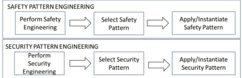
Safety Pattern Engineering. Safety Pattern Engineering involves safety-related tasks and is composed of three main tasks (cf. Fig. 2), which will be described in the following paragraphs.
Fig. 2. Safety pattern engineering and security pattern engineering tasks
Perform Safety Engineering. As described above, patterns are used to tackle specific problems; therefore, we need to have a good understanding of the system and the context in order to select and apply patterns appropriately. The workflow starts with established
safety engineering approaches and techniques that need to be carried out until Safety Requirements (Functional or Technical) are available.
Select Safety Pattern. The decision about which pattern best fits a specific system should be analyzed taking into account the problem to be addressed and the context of the system. Besides, there are a few trade-offs that one needs to take into consideration when choosing an architectural pattern, such as costs (hardware, development effort) or standardization. The Safety Requirements guide safety engineers into selecting a safety. Current state-of-the-art [3, 12, 13] provides many patterns with detailed information about the impact in the system in the view of different dimensions (e.g. Cost, Reliability, Safety). There might be cases that no pattern is suitable for the discovered problems, thus the engineer needs to come up with an ad-hoc solution.
Apply/Instantiate Safety Pattern. The engineers should apply the safety pattern to the architecture, performing required changes on the architecture or on the pattern. Using the pattern “as-is” is usually not possible and some adaptation might be required. The updated system architecture is the prerequisite for the next task.
Security Pattern Engineering. In the previous phase, the architecture was updated with safety measures. In the second phase, Security Pattern Engineering, the architecture will be analyzed with regard to security vulnerabilities. The weak points are to be addressed by applicable security patterns and a secure architecture will be the output of this phase.
Perform Security Engineering. In this step, Security Engineering is performed on the existing system context such as functional requirements, results of Safety Engineering, and intermediate architectural design of the system, including the safety patterns. Estab lished Security Engineering methods and techniques such as attack surface analysis, attack trees, and threat modeling can be used to identify vulnerabilities and threats. The results of this task leads to security measures that either mitigate potential threats or reduce the risks to an acceptable level. Special attention is given to vulnerabilities caused by safety patterns.
Select Security Pattern. The security engineers should give priority to the selection of re-usable security solutions from well-established security patterns for mitigating the security risks. If multiple security patterns are available, the selection of a security pattern is then a design decision that optimizes cost-benefit. Similar to the selection of safety patterns, if no security pattern is available, an ad-hoc solution is applied. Apply/Instantiate Security Pattern. In this step, the instantiated security pattern is incorporated into the existing system architecture design. If the information how to integrate is not available in the pattern description, the security engineers should adapt the security pattern to the specific system context and requirements.
Safety and Security Co-engineering Loop. After the initial two phases of the Pattern Engineering Lifecycle, the Safety and Security Co-Engineering Loop starts. In this
phase, lightweight versions of safety pattern engineering and security pattern engi neering take place one after the other until no extra modification is required in the archi tecture. The fact that they are performed as a lightweight version means that the focus is on checking those aspects that experienced alteration and their respective influence on the overall system.
The Loop starts with the safety pattern engineering task requiring safety engineers to analyze how the newly added security patterns might impact the system safety. Some security architecture strategy might impair, for example, the communication time between components, causing a command to arrive late. Also in this task, the results of the first security pattern engineering phase help the safety engineers to identify further points of failure that could be caused by an attack. The initial safety pattern might require some modification to add extra safety.
On the other hand, if the newly proposed safety mechanisms imply new vulnerabil ities or changes in the attack surface, the security engineers should detect, assess, and propose new solutions. This is what happens during the security pattern engineering performed in the lightweight version. This goes on like a cycle and stops when the system fulfills the desired safety and security requirements. Updating supporting documentation and updating the architecture are also tasks to be performed.
4
Implementation of Pattern Engineering Approach
In the following section, the technical implementation of the approach shall be demon strated on an automotive case study.
4.1 Use Case Description
Our automotive use case example of a connected electrified hybrid powertrain is a combination of one or more electric motor(s) and a conventional internal combustion engine, which is currently the most common variant of hybrid powertrains. The variety of powertrain configuration options increases the complexity of the powertrain itself as well as the required control systems, which include software functions and electronic control units. With the integration of connectivity features, further novel vehicle func tionalities and new business models can be discovered. Therefore, we focus on an inte gral part of every connected hybrid powertrain, the battery management system (BMS), and its functionalities related to the connection to the external world; in this case espe cially the connections with the charging unit.
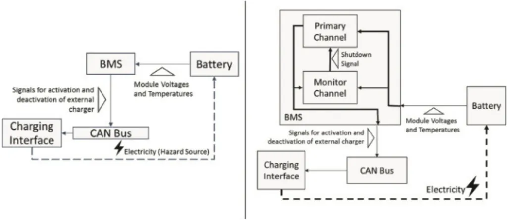
In this paper, we investigate a specific use case scenario of the connected hybrid powertrain use case: charging of the battery system by connecting it with an external charging unit. Figure 3 left shows the most relevant elements: battery satellite modules, battery management system, CAN communication, the charging interface, and the external charging unit.
Fig. 3. Left: Automotive Battery Use Case, Right: Architecture with the safety pattern applied
4.2 Application of the Approach
In this subsection, we apply the Pattern Engineering Lifecycle in the use case scenario presented in the previous subsection. The concept phase is considered in this example. 4.2.1 Safety Pattern Engineering
Perform Safety Engineering. We describe in the following a small summary of the results of this task up to the level of Functional Safety Requirements:
Hazard: Wrong estimation of charging status.
Comment: The battery of electric vehicles can be very dangerous in case of over charging, even causing explosions. If the charging status of a battery is estimated wrongly, extra energy might be supplied, leading to a hazardous situation.
Operational situation: Parking
Comment: The hazard will only happen while charging, and this can only be performed while the car is parked. This hazard might also occur while driving when architectures with regenerative systems are considered.
Hazard classification:
• Severity: 3 || Exposure of frequency: 4 || Controllability: 2 • Resulting hazard ASIL: [C]
• Safety goal: Estimate correct status of cycle while charging. – Safe state: Disconnect HV battery, Alert driver.
• Functional Safety requirement: Detect Failure and errors from BMS.
Select Safety Pattern. The results from Safety Engineering describe two possible safe states for the system that are compliant with the Safety goal. The “Disconnect HV battery” measure would cut off the power supply, the source of the hazard. The “Alert driver” measure would issue a warning to the driver. The car will be in parking mode if the hazard occurs (operational situation: Parking); therefore, full functionality in case of fault occurrence is not required.
We should apply to the architecture a pattern that helps fulfilling the Functional Safety Requirement “Detect Failure and errors from BMS”. We selected the Monitor-Actuator Pattern [12] (cf. Fig. 3 Right) which provides heterogeneous redundancy. This pattern adds to the architecture a monitoring channel that detects possible faults and triggers the primary channel to enter its fail-safe state. The Monitor-Actuator Pattern is suitable to systems with low availability requirements and addresses the problem of finding an appropriate mechanism for detecting failures or errors without incurring higher costs.
Apply/Instantiate Safety Pattern. The Monitor-Actuator Pattern was instantiated as depicted in Fig. 3. Only changes to the BMS component were made.
4.2.2 Security Pattern Engineering
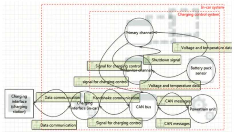
Perform Security Engineering. In this context, Security Engineering follows the initial definition of a safety pattern to identify potential security vulnerabilities, threats, and risks in order to find appropriate countermeasures and apply corresponding security patterns. In this example, we use the threat modeling methodology [8], in which a system is modeled in a data flow diagram (DFD). When modeling the functional blocks from the safety pattern (cf. Fig. 3.) in a DFD, a few transitions and extrapolations occur. First, since threat modeling assumes that attacks happen when data flow from one process (i.e., a software component that takes input and either produces output or performs an action) to another, the logic signal flows in the safety pattern need to be translated into directional data flows according to the software architecture implementing this safety logic. Therefore, additional components are added such as the “CAN bus” process, which represents the communication bus in the in-car system. Second, the trust boun daries need to be defined in the DFD in order to identify attacks originating from data flows across trust boundaries. As a result, the charging interface is split into two parts: an in-car charging interface and the corresponding interface at the charging station. The interface on the charging station is modeled as an external interactor outside the “In-car system” trust boundary. There can be different levels of trust boundaries. In this case, we assume that attacks can only originate from outside the “In-car system” boundary. Third, at the system level, security has an influence on components beyond the scope of the safety pattern. Since the communication between the primary and monitor channel and the charging interface goes through the CAN bus, and the powertrain unit is connected to the same bus, the security of the charging interface also influences the security of the powertrain unit. Thus even though the two safety modules cannot be attacked directly due to the unidirectional data flows, there are risks that an attacker might use the system charging function to attack the powertrain unit. Figure 4 shows the modeled architecture in DFD using the Microsoft Threat Modeling Tool.
The security analysis provides a list of threats according to the STRIDE method. In our case, the threats we identified are the communications from the external charging interface to the CAN bus that is responsible for establishing and maintaining commu nications for charging control. An attacker can use the in-car charging interface as an entry point by compromising the external charging interface or tampering with the communications between the interfaces to inject malicious content into the CAN bus.
Select Security Pattern. One possible solution is to add a security gateway between the external unit and the internal CAN bus as shown in Fig. 5. The security gateway is a security pattern that is placed between an unprotected internal network and untrusted external entities when communication to the outside is inevitable. As a repeatable solu tion, the security gateway is not limited to the charging interface. It can be applied to any communication between the CAN bus and untrusted external devices. In general, it controls the network access to the internal ECUs according to predefined security poli cies and can also inspect packet content to detect intrusion attempts and anomalies. It can also serve as an endpoint for secure communication with external entities that implement network or application level securities. In this way, it adds security protection and segments the system without fundamentally changing the existing in-car system architecture.
Fig. 5. Security Gateway as a security pattern (Tool: MS Threat Modeling Tool 2016)
Apply/Instantiate Security Pattern. In Fig. 5, we see the altered architecture with the Security Gateway module. Beyond the many benefits, a security gateway might intro duce latency into the communication, which is a subject of safety impact analysis. 4.2.3 Safety and Security Co-engineering Loop
First Safety Pattern Engineering Iteration. With the inputs from previous tasks we perform a HAZOP analysis to identify potential anomalies in the provision of the service
controlling the Charging Interface (cf. Table 1). The focus is thus on the changes performed to the architecture by the security engineers.
Table 1. HAZOP Guideword analysis of the architecture. Function: Command to the charging interface to stop charging
Guideword Possible causes Possible consequences
Commission – –
Omission The Gateway blocks a message to stop charging. Message gets corrupted
The Charging Interface keeps providing energy to the battery
Early – –
Late The extra processing time required slows the reaction time of the components
Battery is charged for a couple of hundreds of milliseconds more than required
Value High – –
Value Low – –
Based on the analysis we identified failure modes Omission and Late as potential causes of a hazard (cf. Table 1). Other potential failure modes are not relevant for this scenario. As input from the Security Pattern Engineering phase, we get the information that the Security Gateway adds a small latency to the communication between the Charging Interface and the BMS. This small delay can cause a minor amount of extra charging in the battery which is not a source of hazard.
From the input received from the previous phase, we also discovered that the safety functions on the charging interface will not suffice in the case of a hacker attack. To tackle this issue a Charging Interface fail-safe device connected to the Monitor channel was integrated (cf. Fig. 6). Of course, one obvious drawback in this solution is the extra cost incurred due to extra hardware and installation.
First Security Pattern Engineering Iteration. The changes in the architecture neither create new vulnerabilities nor jeopardize the current mechanisms already in place. Since further modification of the architecture was not required, the Loop reaches an end. After finalization of the safety and security pattern engineering activities, the design can be reviewed to check whether all applied patterns can co-exist and whether there is no
unwanted influence. While there is a direct review of the design with the applied patterns after each iteration, a final check can ensure the soundness of the design. It was decided to add the Security Gateway as an additional component in the system, to not only ensure that safety pattern and the security pattern do not interfere with each other, but also to support the maintainability of the security solution. Updates to the gateway do not impact the safety pattern directly.
5
Discussion
The availability of recurring process steps, based on automotive industry standards, results in faster and cheaper product development while fulfilling the need for intangible product properties, namely safety and security. This means that if, for instance, a safety (architectural) pattern is selected to address a specific safety requirement, additional information and guidance with respect to neuralgic aspects from a security point of view is needed. These might be subject to further security analyses and the application of an additional security (architectural) pattern might be warranted. The security pattern, in turn, can have a safety impact, which is again explicitly specified.
The decision about which pattern fits best for a specific system should be analyzed taking into account the problem to be addressed and the context of the system. Besides, there are a few trade-offs that one needs to take into consideration when choosing an architectural pattern, such as costs (e.g. available hardware, development effort) or standardization. These trade-offs are project specific can also involve managerial deci sions.
As stated, safety and security engineering are very closely related disciplines and their synergy can be fostered when their similarities are recognized and adequate inter actions are established correctly.
6
Conclusion and Future Work
This paper focused on the selection, combination, and application of safety and security patterns. The introduction of the Pattern Engineering Lifecycle provided a systematic way of safety- and security-related pattern engineering process steps to development, and included already existing work products, such as the results of safety analyses. The Safety and Security Co-Engineering Loops helped to align these activities systemati cally. It benefits from tight integration of safety- and security-related process steps, which requires increased exchange of information between them.
An industrial use case demonstrated the practical realization of our approach: the architecture of an automotive battery system was described in a semi-formal way, including identification of its main components, physical interconnections, and flows of information. Within the Safety Pattern Engineering step, the “Monitor-Actuator Pattern” was selected as an appropriate measure for detecting failures originating from the BMS. Within the Security Pattern Engineering step, the “Security Gateway Pattern” was selected to protect the CAN bus from attacks on the Charging Interface. During the Safety and Security Co-Engineering Loop, the conducted HAZOP analysis identified
additional modifications to the overall system. As result, a dedicated risk reduction measure was proposed to enhance the integrity due to combination of the two patterns. Finally, the complete system was presented after the first iteration of the introduced Safety and Security Co-Engineering Loop.
With the presented approach, we aimed to derive the manifold benefits from patterns inherent to their nature. This is a mean for accelerating the application of adequate safety and security co-engineering in the automotive domain. In particular, we showed a way to remediate the lack of security knowledge and facilitate easier and more informed integration of these two “separate” yet interfering disciplines. Future work should inves tigate an advanced model-based tool support for the proposed steps of the approach with interfaces to existing external tools.
Acknowledgment. This work is supported by the EU projects EMC2 and AMASS. Research leading to these results has received funding from the EU ARTEMIS Joint Undertaking under grant agreement n° 621429 (project EMC2), EU ECSEL Joint Undertaking under grant agreement n° 692474 (project AMASS), and from the COMET K2 - Competence Centres for Excellent Technologies Programme of the Austrian Federal Ministry for Transport, Innovation and Technology (bmvit), the Austrian Federal Ministry of Science, Research and Economy (bmwfw), the Austrian Research Promotion Agency (FFG), the Province of Styria, and the Styrian Business Promotion Agency (SFG), the German Federal Ministry of Education and Research (BMBF), grant “CrESt, 01IS16043”.
References
1. International Organization for Standardization: ISO 26262 - Road vehicles– Functional safety, Part 1–10. ISO/TC 22/SC 32 - Electrical and electronic components and general system aspects (2011)
2. Preschern, C., Kajtazovic, N., Kreiner, C.: Building a safety architecture pattern system. In: Proceedings of the 18th European Conference on Pattern Languages of Program, p. 17. ACM (2015)
3. Armoush, A.: Design patterns for safety-critical embedded systems, Doctoral dissertation, RWTH Aachen University (2010)
4. Schmittner, C., Ma, Z., Schoitsch, E., Gruber, T.: A case study of FMVEA and CHASSIS as safety and security co-analysis method for automotive cyber-physical systems. In: Proceedings of the 1st ACM Workshop on Cyber-Physical System Security. ACM (2015) 5. Schumacher, M.: Security Engineering with Patterns: Origins, Theoretical Models, and New
Applications, vol. 2754. Springer, Heidelberg (2003)
6. Delessy, N.A., Fernandez, E.B.: A pattern-driven security process for SOA applications. In: Third International Conference on Availability, Reliability and Security, ARES 2008, pp. 416–421. IEEE, March 2008
7. Petroulakis, N.E., Spanoudakis, G., Askoxylakis, I.G., Miaoudakis, A., Traganitis, A.: A pattern-based approach for designing reliable cyber-physical systems. In: Global Communications Conference (GLOBECOM), pp. 1–6. IEEE, December 2015
8. Shostack, A.: Threat Modeling: Designing for Security. Wiley, Hoboken (2014)
9. Alexander, C., Ishikawa, S., Silverstein, M., Ramió, J.R., Jacobson, M., Fiksdahl-King, I.: A Pattern Language, pp. 311–314. Gustavo Gili, Barcelona (1977)
10. SAE International: J3061 - Cybersecurity Guidebook for Cyber-Physical Vehicle Systems (2016)
11. Vlissides, J., Helm, R., Johnson, R., Gamma, E.: Design Patterns: Elements of Reusable Object-Oriented Software. Addison-Wesley, Reading (1995). 49(120), 11
12. Douglas, B.: Real-Time Design Patterns: Robust Scalable Architecture for Real-Time Systems. Pearson, Essex (2002)
13. Douglas, B.: Design Patterns for Embedded Systems in C. Elsevier, Amsterdam (2010) 14. Pullum, L.L.: Software Fault Tolerance Techniques and Implementation. Artech House Inc,
Norwood (2001)
15. Macher, G., Armengaud, E., Kreiner, C., Brenner, Schmittner, C., Ma, Z., Martin, H., Krammer, M.: Integration of Security in the Development Lifecycle of Dependable Automotive CPS. Handbook of Research for Cyber-Physical Systems Ubiquity. IGI Global (2017)
16. Macher, G., Sporer, H., Berlach, R., Armengaud, E., Kreiner, C.: SAHARA: a security-aware hazard and risk analysis method. In: Design, Automation Test in Europe Conference Exhibition, pp. 621–624 (2015)
17. Schmittner, C., Ma, Z., Gruber, T., Schoitsch, E.: Safety and Security Co-engineering of Connected, Intelligent, and Automated Vehicles. ERCIM News #109 (2017)