O
VER
-
THE
-A
IR
B
OOTLOAD
S
ERVER AND
C
LIENT
S
ETUP
U
SING
EM35
X
D
EVELOPMENT
K
ITS
This application note describes the process users should follow to perform a ZigBee over-the-air (OTA) bootload cluster download between a client and server device, and how to perform an Ember Standalone one-hop bootload. The instructions show an Application bootloader for a Smart Energy 1.x devices, while the Standalone Bootloader uses a Home Automation 1.x device. The hardware used in both cases is Ember® EM35x development kits. Users can also refer to this procedure when setting up or testing OTA bootload downloads in their own development environments with their own hardware.
New in This Revision
Updates for local storage bootloader support.
Contents
1 Introduction ... 3
1.1 ZigBee Over-the-air Bootload Example ... 3
1.2 Ember Standalone 1-hop download Example ... 3
2 Hardware and Software Requirements ... 3
2.1 Client Hardware ... 3
2.2 Server Hardware ... 4
2.3 ZigBee OTA Hardware Diagram ... 4
2.4 Standalone OTA Hardware Diagram ... 5
3 General Procedure ... 5
3.1 Similarities between the Standalone and ZigBee OTA Application Setup ... 5
3.2 Configure the ZigBee OTA Client ... 6
3.3 Configure the Standalone OTA Client ... 7
3.4 Building the Client (Standalone or ZigBee OTA) ... 8
3.5 Copy the OTA Client Image ... 8
3.6 Configure the ZigBee OTA Server ... 8
3.7 Configure the Standalone OTA Server ... 9
3.8 Build the Server (Standalone or ZigBee OTA) ...10
3.8.1 Building on a Linux Box ...10
3.8.2 Building on a Windows Box Under Cygwin ...11
3.9 Build a Second ZigBee OTA Client Image ...11
3.9.2 Build the Second OTA Client Image ...12
3.9.3 About the ZigBee OTA Image File Format ...12
3.9.4 Generate the ZigBee OTA Image File ...13
3.10 Load the Client Software ...15
3.11 Load Standalone Bootloader Key into Chip ...16
3.12 Load the NCP Server Software ...16
3.13 Load the Second OTA Client Image on the Server ...16
3.14 Running the ZigBee OTA Client / Server ...17
3.15 Running the Standalone OTA Client / Server ...19
3.16 Repeating the Procedure ...22
3.16.1 Downgrade the Running Image to the Old Version ...22
3.16.2 Create Another Image with a Newer Software Version ...22
4 Advanced Topics ...22
4.1 Specifying Your Own Manufacturer ID ...22
4.2 Specifying Your Own Image Type ID ...23
4.3 Modifying the OTA Client to Use a Different EEPROM...23
4.4 Using a Cross-compiler for the OTA Server ...24
4.5 Using Encrypted EBL Images ...24
4.5.1 Changing the Bootloader Type ...24
4.5.2 Load a Secure Bootloader onto the device ...25
4.5.3 Load an Encryption Key onto the Device ...25
4.6 Using Signed Image Files...25
4.6.1 Obtaining the Necessary ECC Components ...26
4.6.2 Configuring the client with ECC Support and Signature Verification ...26
4.6.3 Server Configuration ...26
4.6.4 Building and Signing the Client image...26
4.6.5 Using a Manufacturer-Specific Certificate ...27
4.6.6 Loading the Client Software...27
4.6.7 Loading the Server Software ...27
4.6.8 Loading the Client and Server Certificate ...27
4.6.9 Loading the Signed Image on the Server ...28
1 Introduction
This application note describes the steps necessary to demonstrate two scenarios using bootloading:
1. A ZigBee over-the-air (OTA) bootload cluster download between a client and server device. The procedures use Smart Energy 1.x devices and EM35x development kits.
2. An Ember Standalone Bootload 1-hop download between a client and a server. The procedure uses Home Automation 1.x devices and EM35x development kits.
While this application note does not explicitly show the procedure other configurations are possible, such as using the ZigBee OTA cluster with a Home Automation device.
1.1
ZigBee Over-the-air Bootload Example
This is an example of an application bootloader, which requires a block of storage to download the entire image before it is copied to the EM35x chip. This is not an example of the standalone bootloader. Please refer to the document UG103.6, Application Development Fundamentals: Bootloading, for more details about the differences between the two bootloader types.
Refer to this application note when setting up and or testing the ZigBee OTA bootload cluster on your own. The Advanced section of this document describes how this example can be expanded to use your own hardware configuration, and how to change the software configuration to support your own manufacturer-specific information. For further reference please see:
• ZigBee Over-the-Air Bootload Cluster Documentation – ZigBee Document 09-5264
• Silicon Labs document UG102, Ember Application Framework Developer Guide – Chapter 15
• Silicon Labs document AN714, Smart Energy ECC-Enabled Device Setup Process
1.2
Ember Standalone 1-hop download Example
This is an example of a standalone bootloader, which does not require external storage during the bootload
process. When the download is occurring the normal application is not running and will not receive or route ZigBee messages. This is a destructive process where the current running application is overwritten as the download occurs. This method uses a proprietary protocol using Xmodem on top of MAC messages. The MAC messages are not ZigBee standard messages and thus cannot be routed by the Zigbee network. For more information please see the following:
• Silicon Labs document UG103.6, Ember Application Development Fundamentals:Bootloading
• Silicon Labs document AN760, Using the Standalone Bootloader
2 Hardware and Software Requirements
2.1
Client Hardware
The client hardware used in these procedures is an Ember EM35x development kit run in system-on-chip mode (SOC). For the application bootloader there are two choices for the download space. The first is an external serial dataflash chip connected to the EM35x. The second option is only available to a subset of EM35x chips and that is to use a portion of the main flash as the download space (called the local storage application bootloader). For a list of chips that support the local storage bootloader, please refer to UG103.6—AppDev Fundamentals: Bootloading. The Ember EM35x development kit breakout board rev B3 ships with an Atmel AT45db021d part with 264 kB of memory attached to the breakout board, which can be used in these procedures. The newer Ember EM35x
development kit rev C3 has a WinBond part W25Q80BVSNIG with 256 kB of memory and can also be used with these procedures.
The ZigBee OTA client cluster can be used with an Ember EM35x chip running in either SOC or network
coprocessor mode. This document does not show how to do this, but the server hardware and setup described in section Server Hardware is the same when the client is using EZSP. This application note shows one example of how the OTA client cluster can be used with a specific hardware configuration.
The client software is Ember application framework contained within the latest version of the EmberZNet PRO stack for the EM35x.
2.2
Server Hardware
The server hardware is an EM35x development kit run in network coprocessor (NCP) mode. In this application note either a Linux system or Windows PC with Cygwin is required to run the host software that connects to the EM35x NCP. The storage for the OTA software images is the PC’s local file system.
It is possible for an OTA server to run on an EM35x SOC, or to use an EM35x NCP with a different host system such as the STM32f103ret. A different configuration than the one presented here requires an alternative
mechanism for pushing images into the OTA server so they can be then served up to clients through the ZigBee OTA bootload cluster protocol. For example, software images could be pushed through a utility backhaul, an Ethernet connection to a local network, or some other proprietary mechanism.
A Linux system connected to an EM35x NCP is only one possible option to serve up OTA files. It was the friendliest option for an OTA server because there are many mechanisms to push OTA files into the server’s file system.
2.3
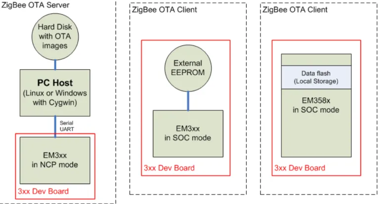
ZigBee OTA Hardware Diagram
Figure 1 shows a diagram of the hardware configuration used for the ZigBee OTA application bootload procedures. Note that only one client is required.
2.4
Standalone OTA Hardware Diagram
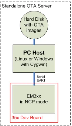
Figure 2 shows a diagram of the hardware configuration used for the Standalone OTA bootload procedures:
Figure 2 - Standalone OTA Hardware Setupq
3 General Procedure
The following outlines the steps to configure the OTA bootload cluster client and server. Details are presented in subsequent sections.
1. Configure and build the OTA client. 2. Copy the first client image.
3. Configure and build the OTA server. 4. Build the second OTA client image
5. Generate a ZigBee OTA image file for the OTA server. 6. Load the client software.
7. Load the NCP server software.
8. Load the second OTA client image on the server. 9. Run the client / server setup.
3.1
Similarities between the Standalone and ZigBee OTA Application Setup
The ZigBee OTA server and Standalone OTA server setup are very similar. The Standalone OTA server will actually utilize the ZigBee OTA server plugins and storage device (in this example a PC host) to store the new
image. The actual download mechanism will use the Standalone Bootloader plugins. In order for the ZigBee OTA storage code to manage the images they must be wrapped in the OTA file format. Therefore even though the standalone bootloader itself does not need the OTA file format, this application note describes how to wrap the EBL file into an OTA file as a necessary step for the process.
On the client side the Standalone and ZigBee OTA setup has more differences because the Standalone client setup does not need any storage device and does not use the ZigBee OTA client code.
3.2
Configure the ZigBee OTA Client
The ZigBee OTA client is configured using Ember AppBuilder. For more information on configuring an application using Ember AppBuilder, refer to document UG102, Ember Application Framework Developer Guide. Ember AppBuilder is provided as a stand-alone application, and as a plugin within Ember Desktop. The following instructions assume access through Ember Desktop.
This procedure configures a ZigBee Smart Energy 1.x In-Premise Display (IPD) as an example. Other device types can be configured similarly. The example setup includes support for the ZigBee OTA bootload cluster client. The client software does not require that OTA images be signed and verified in order to successfully bootload them. See the section Using Signed Image Files for details on how to use signed images.
Here are the basic steps to configure the OTA client: 1. Launch Ember Desktop.
2. From the File menu, select New-> ZigBee Application Configuration.
3. Select the appropriate EmberZNet PRO stack for EM35x SOC, for example EmberZNet 5.0 GA EM35X.
4. Select the ZCL Cluster Configuration tab.
1. Name your application by typing a name in the Device Name text entry box, for example OtaClient. 2. From the ZCL Device Type, select SE Devices, then select SE In-Premises Display.
3. In the Cluster List pane on the bottom left, expand the General group. 4. Select the Over-the-Air Bootloading Cluster client checkbox.
5. Switch to the Stack Configuration tab.
1. Scroll down to the Debug Printing section. Turn on print output for the over-the-air cluster so that in subsequent steps you can verify what is happening on the device.
2. Expand the Cluster Debugging group.
3. Check the Compiled-in and Enabled at startup checkboxes for the Over-the-Air Bootloading cluster. 6. Switch to the HAL Configuration Tab.
IMPORTANT: Make sure to specify a bootloader as described in the next step. See the note at the end of this procedure.
7. Under the Bootloader section, open the Bootloader drop-down menu and specify Application or Local Storage.
8. Switch to the Plugins Tab. Make sure the following plugins are checked (other plugins may be checked by default as well):
• OTA Bootload Cluster Client
• OTA Bootload Cluster Client Policy
• OTA Bootload Cluster Common Code
• OTA Bootload Cluster Storage Common Code
• OTA Simple Storage Module
• OTA Simple Storage EEPROM Driver
• EEPROM
• OTA Cluster Platform Bootloader
1. Check the Perform EBL Verification (SOC Only) checkbox. 2. In the Firmware Version text entry box, set the value to 1. 10. Select the OTA Simple Storage EEPROM Driver.
1. Check the SOC Bootloading Support checkbox. 11. Save your configuration (ISC) file (has the extension .isc).
1. Open the File menu and select Save.
12. Enter an appropriate name, for example OtaClient.isc. 13. Click Generate.
Note: An EEPROM/dataflash driver is not specifically included in the application’s project file. The application will call into the bootloader’s storage driver code to perform the low-level calls to the Atmel dataflash. This is why it is important to enable a bootloader in the client configuration and later to load a bootloader into the device.
3.3
Configure the Standalone OTA Client
The Standalone OTA client is configured using Ember AppBuilder. For more information on configuring an application using Ember AppBuilder, refer to document UG102, Ember Application Framework Developer Guide. Ember AppBuilder is provided as a stand-alone application, and as a plugin within Ember Desktop. The following instructions assume access through Ember Desktop.
This procedure configures a Home Automation On-Off client. Other device types can be configured similarly. The example setup includes support for the Standalone OTA bootload client.
Here are the basic steps to configure the OTA client: 1. Launch Ember Desktop.
2. From the File menu, select New-> ZigBee Application Configuration.
3. Select the appropriate EmberZNet PRO stack for EM35x SOC, for example EmberZNet 5.0 GA EM35X.
4. Select the ZCL Cluster Configuration tab.
1. Name your application by typing a name in the Device Name text entry box, for example StandaloneClient.
2. From the ZCL Device Type, select HA Devices, then select HA On-Off Switch. 5. Switch to the Stack Configuration tab.
1. Scroll down to the Debug Printing section. Turn on print output for the over-the-air cluster so that in subsequent steps you can verify what is happening on the device.
2. Expand the Cluster Debugging group.
3. Check the Compiled-in and Enabled at startup checkboxes for the Over-the-Air Bootloading cluster. 6. Switch to the HAL Configuration Tab.
IMPORTANT: Make sure to specify a bootloader as described in the next step. See the note at the end of this procedure.
1. Under the Bootloader section, open the Bootloader drop-down menu and specify Standalone. This supports the standalone OTA bootloader.
7. Switch to the Plugins Tab. Make sure the following plugins are checked (other plugins may be checked by default as well):
• Standalone Bootloader Client
• Standalone Bootloader Common
8. Save your configuration (ISC) file (has the extension .isc). 9. Open the File menu and select Save.
10. Enter an appropriate name, for example StandaloneClient.isc. 11. Click Generate.
3.4
Building the Client (Standalone or ZigBee OTA)
1. Launch IAR Embedded Workbench (EWARM).
The version of IAR EWARM used should correspond to the stack’s required complier version. For example, EmberZNet PRO 5.0 requires IAR EWARM 6.40.2.
2. Open the project file that was generated by Ember Desktop. 3. Select the Tools menu and the Rebuild All option.
The project should successful compile all targets. By default IAR Workbench will not show the post build
processing output. The post build processing output will display the flash and RAM usage of the application. For a ZigBee OTA Bootload Cluster Client there will also be a post build conversion to a ZigBee OTA file format. See section 3.9.4 Generate the ZigBee OTA Image File.
To see the output of the post processing you must change the Build Output setting in IAR Workbench. Go to the
Tools Menu and select Options, then select Messages from the list at the left. The first option on the right side should be Show Build Messages. Change the drop-down menu to All.
3.5
Copy the OTA Client Image
The procedures in this application note build two client images, the old version and the new version. The image that was generated in the previous step is the old version. This image will run before the ZigBee OTA process upgrades the client device. Copy this file to another location outside of the build directory so that it is not destroyed in a later step. Name it appropriately based on the version number. For example:
1. Launch a DOS Prompt 2. Type the commands:
cd “Program Files\Ember\EmberZNet5.0.0-GA\em35x” copy build\OtaClient\OtaClient.ebl OtaClient-v1.ebl
3.6
Configure the ZigBee OTA Server
The OTA server is configured using Ember AppBuilder. For more information on configuring an application using Ember AppBuilder, refer to document UG102, Ember Application Framework Developer Guide. Ember AppBuilder is provided both as a stand-alone application and as a plugin within Ember Desktop. The following instructions assume access through Ember Desktop.
This procedure creates a ZigBee Smart Energy 1.x Energy Services Interface (ESI) device. The device includes support for the ZigBee over-the-air bootload cluster server. The host server software can support both signed and unsigned OTA images since it will not do any verification on these files.
Here are the basic steps to configure the OTA server: 1. Launch Ember Desktop.
2. From the File menu, select New-> ZigBee Application Configuration.
3. Select the appropriate EmberZNet PRO stack for building an EZSP application connecting to an EM35x NCP, for example, EmberZNet 5.0 GA EM35X-EZSP.
4. Select the ZCL Cluster Configuration Tab.
1. Name your application by typing a name in the Device Name text entry box, for example OtaServer. 2. From the ZCL Device Type, select SE Devices, then select SE Energy Service Interface.
3. In the Cluster List pane on the bottom left, expand the General group. 4. Select the Over-the-Air Bootloading Cluster server checkbox. 5. Select the Stack Configuration tab.
1. Scroll down to the Debug Printing section. Turn on print output for the over-the-air cluster so that in subsequent steps you can verify what is happening on the device.
2. Expand the Cluster Debugging group.
3. Check the Compiled-in and Enabled at startup checkboxes for the over-the-air bootloading cluster. 6. Select the HAL Configuration tab.
1. Under the Platform Configuration section, open the Host drop-down menu and select UNIX Uart Host. 7. Select the Plugins tab. Make sure the following plugins are checked (other plugins may be checked as well):
• Concentrator Support
• Gateway Support
• OTA Bootload Cluster Common Code
• OTA Bootload Cluster Server
• OTA Bootload Cluster Server Policy
• OTA Posix Filesystem Storage Module
8. Save your configuration (ISC) file (has the extension .isc). 1. Open the File menu and select Save.
2. Enter an appropriate name, for example OtaServer.isc. 9. Click Generate.
3.7
Configure the Standalone OTA Server
The Standalone OTA server is configured using Ember AppBuilder. For more information on configuring an application using Ember AppBuilder, refer to document UG102, Ember Application Framework Developer Guide. Ember AppBuilder is provided both as a stand-alone application and as a plugin within Ember Desktop. The following instructions assume access through Ember Desktop.
This procedure creates a Home Automation Gateway with Standalone bootloader server support. The configuration also includes support for the ZigBee over-the-air bootload cluster server even though this device is intended to support a Standalone bootload. This is due to the fact that the ZigBee OTA server provides support for storage of images.
Here are the basic steps to configure the Standalone OTA server: 1. Launch Ember Desktop.
2. From the File menu, select New-> ZigBee Application Configuration.
3. Select the appropriate EmberZNet PRO stack for building an EZSP application connecting to an EM35x NCP, for example, EmberZNet 5.0 GA EM35X-EZSP.
4. Select the ZCL Cluster Configuration Tab.
1. Name your application by typing a name in the Device Name text entry box, for example StandaloneServer.
2. From the ZCL Device Type, select HA Devices, then select HA On/Off Switch. 3. In the Cluster List pane on the bottom left, expand the General group.
4. Select the Over-the-Air Bootloading Cluster server checkbox. 5. Select the Stack Configuration tab.
1. Scroll down to the Debug Printing section. Turn on print output for the over-the-air cluster so that in subsequent steps you can verify what is happening on the device.
2. Expand the Cluster Debugging group.
3. Check the Compiled-in and Enabled at startup checkboxes for the over-the-air bootloading cluster. 6. Select the HAL Configuration tab.
1. Under the Platform Configuration section, open the Host drop-down menu and select UNIX Uart Host. 7. Select the Plugins tab. Make sure the following plugins are checked (other plugins may be checked as well):
• Concentrator Support
• Gateway Support
• OTA Bootload Cluster Common Code
• OTA Bootload Cluster Server
• OTA Bootload Cluster Server Policy
• OTA Posix Filesystem Storage Module
• Standalone Bootloader Common
• Standalone Bootloader Server
• Xmodem Sender
8. Save your configuration (ISC) file (has the extension .isc). 1. Open the File menu and select Save.
2. Enter an appropriate name, for example StandaloneServer.isc. 9. Click Generate.
3.8
Build the Server (Standalone or ZigBee OTA)
Building the OTA Server can be done either on a Linux box using GCC, or a Windows box running Cygwin and GCC. Both processes are described below.
3.8.1 Building on a Linux Box
Building the OTA server can be done on a Linux system. This application note assumes that you are NOT using a cross-compiler and that the target system is the same system as the one where the development tools exist. It is possible to cross-compile for a different Linux system (for example, on an x86 PC targeting an embedded ARM Linux system). See section 4.4 Using a Cross-compiler for the OTA Server for details on how to cross-compile for other systems.
Building the OTA Server for Linux requires a number of development tools. We assume you have access to these tools. They are:
• Make
• GCC
• sed
• awk
• xargs
• The standard C Library and its development headers
• The Readline Library and its development headers (optional)
• The Ncurses Library and its development headers (optional - only needed to support Readline)
The steps to build the OTA server under Linux follow. It is assumed that these steps are run after configuring the server in Ember Desktop.
1. Copy the EmberZNet PRO stack files from their installed location on Windows to a directory on the Linux PC. This should include the Ember Desktop files that were generated in a previous step.
2. Launch a Bash Shell.
3. Change to the root of the EmberZNet directory on your Linux PC.
4. Run Make on the generated Makefile from that directory, for example make –f OtaServer.mak. If Readline support is not desired, then add the NO_READLINE argument, for example make –f OtaServer.mak NO_READLINE
The compilation should complete successfully.
3.8.2 Building on a Windows Box Under Cygwin
Building the OTA Server under Windows requires Cygwin. Cygwin is a set of native Windows tools that emulate a Linux environment. Cygwin can be downloaded from the Internet from http://www.cygwin.com.
Cygwin is actually a collection of hundreds of small programs that make up a Linux distribution. Cygwin can be configured in a myriad of different ways for a particular Windows PC and so by default may not include the required tools for building an EmberZNet PRO host application. Therefore proper installation of the required tools is
necessary before actually building the EmberZNet PRO code.
The following is a general list of the packages necessary to build an EmberZNet PRO host application under Cygwin. • Bash shell • Make • GCC4 • ed • wk • args
• The standard C Library and its development headers
• The Readline Library and its development headers (optional)
• The Ncurses Library and its development headers (optional - only needed to support Readline)
Note: Although it is possible to use the Cygwin tools to build an application that does NOT require the Cygwin DLL, it is not possible to do this with an EmberZNet PRO host application. The host application requires access to the Cygwin DLL to correctly run certain parts of the Ember application framework code. The steps to build the OTA server under Windows using Cygwin are as follows.
1. Launch a Cygwin Shell.
2. Change to the root of the EmberZNet directory.
3. Run Make on the generated Makefile from that directory, for example make –f OtaServer.mak. If Readline support is not desired, then add the NO_READLINE argument, for example make –f OtaServer.mak NO_READLINE
The compilation should complete successfully.
3.9
Build a Second ZigBee OTA Client Image
In order to upgrade devices, we need two different client images, the old version and the new version. The images are identical except for the version number embedded in them.
3.9.1 Generate a New OTA Client Configuration
1. Launch Ember Desktop.
2. Open the previously saved OTA Client ISC file. 1. Open the File menu and select Open.
2. In the dialog box, navigate to the location of the saved ISC file and select Open. 3. Select the Plugins tab.
1. Select the OTA Bootload Cluster Client Policy plugin.
2. Change the value in the Firmware version number entry box to 0x22. This value is an arbitrary choice but it must be greater in value than the previous version (0x01).
4. Click Generate.
3.9.2 Build the Second OTA Client Image
Follow the steps in the previous section, Build the OTA Client, to build the image.
3.9.3 About the ZigBee OTA Image File Format
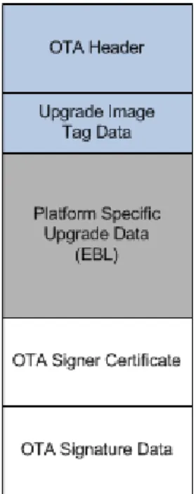
The file format is defined in ZigBee document 09-5264, Over-the-Air Upgrade Cluster Specification. Images are composed of a ZigBee OTA header, followed by one or more blobs of proprietary bootloader data, and then an optional set of cryptographic signature data appended to the end. The OTA server only needs to read the OTA header to serve up the file, and thus can serve up files for different manufacturers and or different products. Figure 2 shows an example of the layout of the file format.
Figure 3. File Format Sent Over-the-Air
Silicon Labs has created a tool for generating OTA images called Image-builder. A detailed guide on how to use this tool can be found in document AN716, Instructions for Using Image Builder.
The non-ECC version of Image-builder is included with the EmberZNet PRO release in the tool\image-builder
sub-directory. This example assumes that the image is not signed. For information on how to use signed images, see Using Signed Image Files in the Advanced section at the end of this document.
When generating an OTA image for the OTA server we must understand the image identity as defined by ZigBee. Three elements uniquely define a ZigBee OTA image file for a particular product:
• ZigBee Manufacturer ID
• Image Type ID
• Version Number
Manufacturer ID
The manufacturer ID is defined by ZigBee. All ZigBee member companies can request a manufacturer ID. These procedures use the Ember Manufacturer ID (0x1002). However it is possible to use a different manufacturer ID. See Specifying Your Own Manufacturer ID in the Advanced section at the end of this document.
Image Type ID
The image type ID is a manufacturer-specific number. It is used to uniquely identify different products by the same manufacturer so that the correct firmware image is downloaded for each device. Each manufacturer can define their own values and they are independent of other manufacturers. These procedures use the default image type ID of 0x0000. However, it is possible to use a different value. See Specifying Your Own Image Type ID in the
Advanced section at the end of this document.
Version Number
The version number is a 32-bit value and can be changed based on whatever the manufacturer’s own versioning scheme is. A manufacturer can also use different version numbers for different products as long as they are differentiated by their Image Type IDs. Two version numbers are being used in these procedures, the old image’s version number (0x00000001) and the new image’s version number (0x00000022).
The only consideration for choosing a version number is how OTA servers treat version numbers. For two software images with the same manufacturer ID and image type ID, an OTA server will consider an OTA file as an upgrade from a previous version if version B is greater than version A. Therefore it is highly recommended that newer versions are higher in integer value than older versions, as is the case in these procedures.
Signing
This application note assumes that images do not need to be signed. For details on how to set up the client and server for signing, please see Using Signed Image Files in the Advanced section at the end of the document.
Tags
Tags are elements within the ZigBee OTA file format for arbitrary blobs of data. They are generally defined by the manufacturer and can contain whatever data is needed for an upgrade. However, ZigBee defines a few standard tags. The tag of 0x0000 indicates an Upgrade image. See document AN716, Instructions for Using Image Builder, for more details.
By default, the Silicon Labs implementation of the OTA Cluster Platform Bootloader plugin looks for a tag value of 0x0000 within the ZigBee OTA image that contains an EBL file. It will attempt to bootload this file.
Also, the OTA Bootload Cluster Client Policy plugin validates the EBL file within tag 0x0000 if the checkbox Perform EBL verification has been checked in Ember Desktop.
3.9.4 Generate the ZigBee OTA Image File
Starting with EmberZNet 5.0, AppBuilder will automatically create a Windows BAT file that will execute Image-builder and wrap the EBL file in the ZigBee OTA file format. This will be done as part of the Post Build step defined in the IAR Project file. The parameters passed to image-builder will be based upon those specified in the
application configuration, specifically the values declared in the “OTA Bootload Cluster Client Policy” plugin.
To see the output of the post processing you must change the Build Output setting in IAR Workbench. Go to the
Tools Menu and select Options, then select Messages from the list at the left. The first option on the right side should be Show Build Messages. Change the drop-down menu to All.
Performing Post-Build Action C:\Users\rbalexan\Ember\EmberZNet5.0.0-GA\EM35x\app\builder\OtaClient357/OtaClient357.bat C:\Users\rbalexan\Ember\EmberZNet5.0.0-GA\EM35x\app\builder\OtaClient357 C:\Users\rbalexan\ Ember\EmberZNet5.0.0-GA\EM35x\build\OtaClient357\OtaClient357 " "
"This converts S37 to Ember Bootload File format if a bootloader has been selected in AppBuilder"
" "
C:\Windows\system32>cmd /c ""C:\Program Files (x86)\Ember\ISA3
Utilities\bin\em3xx_convert.exe" "C:\Users\rbalexan\Ember\EmberZNet5.0.0-GA\EM35x\build\OtaClient357\OtaClient357.s37" "C:\ Users\rbalexan\Ember\EmberZNet5.0.0-GA\EM35x\build\OtaClient357\OtaClient357.ebl" > "C:\Users\rbalexan\Ember\EmberZNet5.0.0-GA\EM35x\build\OtaClient357\ OtaClient357-em3xx-convert-output.txt" em3xx_convert (Version 3.1b15.1361555916) Parse .s37 format for flash
Parse .s37 format for flash Targeting UNKNOWN
Approximate Usage Information: RAM Usage:
APPLICATION_CONFIGURATION_HEADER usage: 0x20000000-0x20000d4b (3404 bytes) Available for future use: 0x20000d4c-0x20001957 (3084 bytes) Call Stack: 0x20001958-0x200020af (1880 bytes) Globals and Statics: 0x200020b0-0x20002fee (3903 bytes) Alignment Overhead: 0x20002fef-0x20002fef (1 bytes) NO_INIT and Debug Channel: 0x20002ff0-0x20002fff (16 bytes) Flash Usage:
Reserved for Bootloader: 0x08000000-0x08001fff (8192 bytes) CODE and Tables: 0x08002000-0x080204cf (124112 bytes) CONST and INITC: 0x080204d0-0x08022403 (7988 bytes) Available for future use: 0x08022404-0x0802dfff (48124 bytes) Reserved for SIMEE: 0x0802e000-0x0802ffff (8192 bytes) Usage Summary:
12288 total bytes RAM, 9204 used, 3084 available
196608 total bytes Flash, 148484 used, 48124 available Create ebl image file
DONE " "
"This creates a ZigBee OTA file if the "OTA Client Policy Plugin" has been enabled. "It uses the parameters defined there. "
" "
C:\Windows\system32>cmd /c
"C:\Users\rbalexan\Ember\EmberZNet5.0.0- GA\EM35x\app\builder\OtaClient357\..\..\..\tool\image-builder\image-builder-windows.exe --create C:\Users\rbalexan\Ember\
EmberZNet5.0.0-GA\EM35x\app\builder\OtaClient357\OtaClient357.ota version 1 --manuf-id 0x0 --image-type 0 --tag-id 0x0000 --tag-file
C:\Users\rbalexan\Ember\EmberZNet5.0.0-GA\EM35x\build\ OtaClient357\OtaClient357.ebl --string "EBL OtaClient357" >
C:\Users\rbalexan\Ember\EmberZNet5.0.0-GA\EM35x\build\OtaClient357\OtaClient357-image-builder-output.txt"
image-builder (C) 2013 by Silicon Labs Version: 1.4.1
ECC signature support NOT present.
File:
C:\Users\rbalexan\Ember\EmberZNet5.0.0-GA\EM35x\app\builder\OtaClient357\OtaClient357.ota Magic Number: 0x0BEEF11E
Header Version: 0x0100 Header Length: 56 bytes Field Control: 0x0000 Manufacturer ID: 0x0000 Image Type: 0x0000 Firmware Version: 0x00000001 Stack Version: 0x0002
Header String: EBL OtaClient357 Total Image Size: 132734 bytes Total Tags: 1
ID: 0x0000 (Upgrade Image) Length: 132672 bytes
3.10
Load the Client Software
Use the Network Analyzer utility, accessed through Ember Desktop, to load the previously built application and a bootloader.
1. Launch Ember Desktop.
2. Open the Window menu, select the Show View sub-menu, and select the Adapters menu item. 3. Select the appropriate EM35x device from the window, right-click and select Connect.
4. Right-click on the EM35x device again, and select Upload Application. 5. In the resulting dialog box:
1. Click on the folder icon to the right of the Browse text entry box, which has the tooltip Browse for a Custom Image.
2. Navigate to the folder containing the previously-built EBL file, the image that was built with a version number of 1.
3. Select the EBL file. 4. Click OK.
6. Check the box labeled Bootloader.
7. Click on the folder icon to the right of the Bootloader drop-down menu.
1. Navigate to the EmberZNet PRO release folder containing the appropriate bootloader and select the S37 file for the EM35x Development Kit hardware,
2. For the ZigBee OTA Client it uses an Application Bootloader. A sample path to the bootloader
is: C:\Program
Files\Ember\EmberZNet5.0.0-GA\em35x\tool\bootloader-em357\app-bootloader\app-bootloader-spi-at45db021d.s37
3. If using a Local Storage Bootloader, a sample path to the bootloader is.
C:\Program Files\Ember\EmberZNet5.1.0-GA\EM35x\tool\bootloader-em3588\app-bootloader-local-storage.s37
4. For the Standalone OTA client it uses the Serial UART OTA bootloader, which supports both bootloading via local UART and over-the-air messages. A sample path to the bootloader is: C:\Program
Files\Ember\EmberZNet5.0.0-GA\em35x\tool\bootloader-em357\standalone-bootloader\serial-uart-ota-bootloader.s37
8. Click OK.
3.11
Load Standalone Bootloader Key into Chip
This step is only necessary when running the standalone bootloader client and server.
The Standalone bootloader will authenticate a request to initiate a bootload by sending a randomly generated challenge to the server. The key used by the client is stored in Manufacturing tokens while the key used by the server is defined in the application image. The following procedure must be followed to load the client’s key: 1. Create a token key file of the format:
# Comments start with ‘#’
TOKEN_MFG_BOOTLOAD_AES_KEY: <ascii-hex-characters> For example, the following would define a key that matches the default key in App Builder.
# Default Standalone bootloader key used by AppBuilder
TOKEN_MFG_BOOTLOAD_AES_KEY: 11111111111111111111111111111111 2. Load the key into the client using em3xx_load
a. em3xx_load --ip <ip-address-of-dev-kit> --cibtokenspatch <key-file>
3.12
Load the NCP Server Software
In order to use the EM357 connected to a PC host through USB it is necessary to load the NCP software onto the EM357 chip. The following describes the process:
1. Launch Ember Desktop.
2. Open the Window menu, select the Show View sub-menu, and select the Adapters menu item. 3. Select the appropriate EM35x device from the window, right-click and select Connect.
4. Identify the EM35x as a coprocessor by doing the following.
1. Right-click on the EM35x device and select Adapter Properties. 2. Open the Radio Processor Drop-down menu.
1. Select EM357-EZSP from the menu.
2. Check the Protect from Auto-discovery Changes checkbox. 3. Click OK.
5. Right-click on the EM35x device again, and select Upload Network Coprocessor Firmware. 6. In the resulting dialog box:
1. Click on the folder icon to the right of the Browse text entry box, which has the tooltip Browse for a Custom Image.
Navigate to the location of the EmberZNet PRO EM35x-EZSP release and select the pre-built NCP image with a bootloader, for example: C:\Documents and
Settings\Administrator\Ember\EmberZNet5.0.0-GA\em35x- ezsp\build\em35x-ezsp-images\EM357\em357-ncp-uart-rts-cts-with-serial-uart-bl-460.hex
2. Click OK.
7. Wait for the device to successfully finish a flash load of the EM35x device.
3.13
Load the Second OTA Client Image on the Server
The OTA Server application looks for OTA files in a directory called ota-files that is a sub-directory from the current working directory where the server application is launched.
1. Launch a Cygwin or Linux shell on the OTA Server PC.
2. Navigate to the directory where the OTA Server application will be run. For example, in Linux:
cd /home/rob/ mkdir ota-files
cp -i OtaClient-v22.ota ota-files/ For example, on Cygwin:
cd /cygdrive/c/Program\ Files/Ember/EmberZNet5.0.0-GA/em35x-ezsp mkdir ota-files
cp –i OtaClient-v22.ota ota-files/
3.14
Running the ZigBee OTA Client / Server
1. Run the OTA Server.
2. Make sure the EM35x development board for the OTA server is connected to the PC with a USB or serial cable.
3. Launch the OTA Server by executing the OTA server application from the command-line, and pass it the location of the communications port. The communications port will either be a USB or serial port device. The method for determining which port the EM35x is connected to depends on the operating system of the host PC.
1. Under Linux
The USB port is registered as /dev/ttyUSBX, where X is a number as assigned by the operating system. For example the following would use ttyUSB0.
1. Launch a Shell.
2. Change to the directory where the OTA Server application is located. This should be the same directory where a sub-directory called “ota-files” exists, for example: cd /home/rob. 3. Enter ./OtaServer –p /dev/ttyUSB0
2. Under Windows
The USB port is either COM1, COM2, COM3, and so on. The following example uses COM1. 1. Launch a Cygwin Shell.
2. Navigate to the directory where the EmberZNet PRO installation is located, for example
cd /cygdrive/c/Program\ Files/Ember/EmberZNet5.0.0-GA/em35x-ezsp 3. Type the command: ./build/OtaServer/OtaServer –p COM1
4. Connect to the OTA Client
1. Launch a Windows command prompt or Linux shell and connect by Telnet to the serial port of the Debug Adapter (ISA3). For example: telnet rob-350 4901.
5. Make sure both the client and server have Over-the-Air Bootloading Cluster printing enabled.
1. Execute the following command on the OTA Client: plugin ota-storage printImages. 2. Execute the following command on the OTA Server: plugin ota-storage printImages
In both cases output should print to the CLI. If no output is visible, go back and verify the configuration of the application and its Debug Printing configuration.
6. Make sure that the client is running the older version of the client software. From the OTA client’s CLI type the following command. You should see the corresponding output:
OtaClient>plugin ota-client info Client image query info
Manuf ID: 0x1002 Image Type ID: 0x0000 Current Version: 0x00000001 Hardware Version: NA
Query Delay ms: 300000 Server Discovery Delay ms: 600000 Download Delay ms: 0 Run Upgrade Delay ms: 600000 Verify Delay ms: 10 Download Error Threshold: 10 Upgrade Wait Threshold: 10
Note that the current version field says 0x00000001.
7. Verify that the OTA Server has a newer image loaded in it. From the OTA server’s CLI type the following command. You should see the corresponding output:
OtaServer>plugin ota-storage printImages Image 0
Header Version: 0x0100 Header Length: 56 bytes Field Control: 0x0000 Manuf ID: 0x1002 Image Type: 0x0000 Version: 0x00000022 Zigbee Version: 0x0002
Header String: Our Test Image Image Size: 146954 bytes Total Tags: 1
Tag: 0x0000 Length: 146880
1 images in OTA storage.
Note that the version number is 0x00000022. The exact size of the image may vary.
8. Erase any previous version file that has been saved in the client. This is not normally necessary in a production system, but in this example it may cause problems. Enter the following command on the client: plugin
ota-storage delete 0.
9. Turn off receive message printing to limit console output during the download. Skipping this step will not negatively impact the functionality.
1. On the server: option print-rx-msgs disable 2. On the client: option print-rx-msgs disable 10. Join the devices into the same network.
1. On the server: network form 24 -1 0x1aaa 2. On the server: network pjoin 254
3. On the client: network join 24 -1 0x1aaa
4. If the client joins successful, then you should see EMBER_NETWORK_UP in the output. 5. Wait until Smart Energy Registration has completed.
11. Start the OTA Client’s state machine. 1. On the client:
OtaClient> plugin ota-client start starting OTA client state machine
Bootload state: Discovering OTA Server
Svc Disc: Starting discovery for cluster 0x0019 Svc Disc: Match found from 0x0000.
Setting OTA Server to 0x0000 Svc Disc: complete.
Bootload state: Get OTA Server EUI
OTA Cluster: setting IEEE address of OTA cluster Last offset downloaded: 0x00000000
No image found in storage.
Query next image response: New image is available for download. Starting download, Version 0x00000022
Bootload state: Downloading Image Download: 0% complete
Download: 5% complete ...
Note: The download may take up to 10 minutes. 12. If all goes well you should see the following output:
Download: 100% complete
Bootload state: Verifying Image Last offset downloaded: 0x00023E6C Starting EBL verification
EBL passed verification.
Custom verification passed: 0x00
Bootload state: Waiting for Upgrade message Sending Upgrade End request.
OTA Cluster: wait for 0 s
RXed timeOut 0x00000000 s, MAX timeOut 0x00000DBB s Adding 2000 ms. delay for immediate upgrade.
Countdown to upgrade: 2000 ms
Bootload state: Countdown to Upgrade Applying upgrade
Executing bootload callback. Reset info: 0x02 (BTL)
3.15
Running the Standalone OTA Client / Server
1. Run the OTA Server.
2. Make sure the EM35x development board for the OTA server is connected to the PC with a USB or serial cable.
3. Launch the OTA Server by executing the OTA server application from the command-line, and pass it the location of the communications port. The communications port will either be a USB or serial port device. The method for determining which port the EM35x is connected to depends on the operating system of the host PC. 1. Under Linux
The USB port is registered as /dev/ttyUSBX, where X is a number as assigned by the operating system. For example the following would use ttyUSB0.
1. Launch a Shell.
2. Change to the directory where the OTA Server application is located. This should be the same directory where a sub-directory called “ota-files” exists, for example: cd /home/rob. 3. Enter ./OtaServer –p /dev/ttyUSB0
The USB port is either COM1, COM2, COM3, and so on. The following example uses COM1. 1. Launch a Cygwin Shell.
2. Navigate to the directory where the EmberZNet PRO installation is located, for example
cd /cygdrive/c/Program\ Files/Ember/EmberZNet5.0.0-GA/em35x-ezsp 3. Type the command: ./build/OtaServer/OtaServer –p COM1
4. Connect to the OTA Client.
5. Launch a Windows command prompt or Linux shell and connect by Telnet to the serial port of the Debug Adapter (ISA3). For example: telnet rob-350 4901.
6. Make sure the server has the Over-the-Air Bootloading Cluster printing enabled.
7. Execute the following command on the OTA Server: plugin ota-storage printImages 8. Verify that the Standalone bootloader key is the same for client and server.
9. Execute the following command on the client: plugin standalone-bootloader-client status 10. You should see the following output:
Client status: None Platform: 0x04 Micro: 0x03 Phy: 0x03 BTL Version: 0x0000 MFG ID: 0x1010 Board Name: ETRX357
MFG Key in Token: 11 11 11 11 11 11 11 11 11 11 11 11 11 11 11 11
11. Execute the following on the server: plugin standalone-bootloader-server status 12. You should see the following output:
Server State: None
Key Data: 11 11 11 11 11 11 11 11 11 11 11 11 11 11 11 11
13. Join the devices into the same network.
1. On the server: network form 24 -1 0x1aaa 2. On the server: network pjoin 254
3. On the client: network join 24 -1 0x1aaa
If the client joins successful, then you should see EMBER_NETWORK_UP in the output.
4. Execute the following on the server: plugin standalone-bootloader-server query 5. You should see the following output on the CLI:
Received Standalone Bootloader message (82): Query Response Received Query response from: (>)000D6F0000E4741B
Bootloader Active: no MFG ID: 0x1010 Hardware Tag: ETRX357 Capabilities: 0x00 Platform: 0x04 Micro: 0x03 Phy: 0x03
6. Once you have successfully queried a target, you can initiate the bootload of that target. This command assumes there is only a single OTA file residing on the server as image number 0. Execute the
following: plugin standalone-bootloader-server bootload target 0 0 7. You should see the following output on the server:
Received Standalone Bootloader message (82): Query Response Received Query response from: (>)000D6F0000E4741B
Bootloader Active: no MFG ID: 0x1010 Hardware Tag: ETRX357 Capabilities: 0x00 Platform: 0x04 Micro: 0x03 Phy: 0x03
Sending launch request to current target
Received Standalone Bootloader message (99): Auth Challenge Checking if bootloader is now active on client
Received Standalone Bootloader message (82): Query Response Received Query response from: (>)000D6F0000E4741B
Bootloader Active: yes MFG ID: 0x1010 Hardware Tag: ETRX357 Capabilities: 0x00 Platform: 0x04 Micro: 0x03 Phy: 0x03
Xmodem Transfer: 0% complete Xmodem Transfer: 5% complete Xmodem Transfer: 10% complete Xmodem Transfer: 15% complete Xmodem Transfer: 20% complete Xmodem Transfer: 25% complete Xmodem Transfer: 30% complete Xmodem Transfer: 35% complete Xmodem Transfer: 40% complete Xmodem Transfer: 45% complete Xmodem Transfer: 50% complete Xmodem Transfer: 55% complete Xmodem Transfer: 60% complete Xmodem Transfer: 65% complete Xmodem Transfer: 70% complete Xmodem Transfer: 75% complete Xmodem Transfer: 80% complete Xmodem Transfer: 85% complete Xmodem Transfer: 90% complete Xmodem Transfer: 95% complete
Xmodem Transfer: 100% complete
Xmodem transfer complete, status: Success
3.16
Repeating the Procedure
Once a ZigBee OTA client is upgraded through the ZigBee over-the-air bootload cluster, it can only be upgraded again if the server has a different version of software. The Standalone bootloader does not have this restriction. In order to perform a ZigBee OTA firmware download again it is necessary to do one of the following:
1. Downgrade the running image of the client to the old version or
2. Create another client image with a newer software version.
3.16.1 Downgrade the Running Image to the Old Version
Re-run the steps in the section title Load the Client Software. Load version 0x00000001 of the software, the old image.
3.16.2 Create Another Image with a Newer Software Version
Run the following steps:
1. Re-run the steps in section titled Configure the OTA Client but specify a different Firmware Version that is greater than 0x00000022.
Make sure that you click Generate to generate the build files.
2. Re-run the steps in sections Build the OTA Client and Generate a ZigBee OTA Image File for the OTA Server. Make sure that the --version argument passed to image-builder reflects the newest version number.
4 Advanced Topics
This section presents a number of advanced topics that allow the developer to customize the bootload to their specific hardware and software.
4.1
Specifying Your Own Manufacturer ID
Follow these steps in order to specify a manufacturer ID other than 0x1002, which is the Ember-specific manufacturing ID.
Each member of the ZigBee alliance has its own manufacturer ID. The list of manufacturer IDs is maintained in ZigBee Document 05-3874 Manufacturer Code Database. If your company does not have a manufacturer ID then it must request one from the ZigBee help desk ([email protected]).
1. When configuring the OTA Client in Ember AppBuilder, do the following: 1. Select the ZCL Cluster Configuration Tab.
2. In the Manufacturer Code text entry box on the right, enter your own manufacturer code. 3. Click Generate.
4. Re-compile the application using IAR workbench.
2. When generating the ZigBee OTA image file, do the following.
1. Specify your own manufacturer ID by passing that value to the --manuf-id argument when executing the image-builder command.
Note: You do NOT need to modify the manufacturer ID of the OTA server in this example. The server may have a different manufacturer ID than the OTA Client. You may choose to modify the manufacturer ID to match the OTA server device that your company is building.
4.2
Specifying Your Own Image Type ID
Follow these steps in order to specify an image type ID other than 0x0000. 1. When configuring the OTA Client in Ember AppBuilder, do the following:
1. Select the Plugin tab.
2. Select the OTA Bootload Cluster Client Policy plugin.
3. In the Image Type ID text entry box, enter your own image type ID code. 4. Click Generate.
5. Re-compile the application using IAR workbench.
2. AppBuilder will automatically update the Windows Batch file command being executed by IAR Workbench to generate a ZigBee OTA file. The new Image Type argument will be passed to image-builder with --image-type.
4.3
Modifying the OTA Client to Use a Different EEPROM
Many different external storage parts are available, and the choice of which one is used is based on many different factors. Document UG103.6, Application Development Fundamentals: Bootloading, details several different parts supported by Silicon Labs and their various device parameters. Those in that list have pre-built application bootloader binaries included with the EmberZNet PRO stack release.
If a different flash part or EEPROM is desired for external storage, then steps must be taken to re-compile the bootloader to support the part. This process is generally described as follows:
1. Launch IAR Workbench.
2. Open the Application Bootloader Project file for the EM35x included with the EmberZNet PRO release. 3. Remove the at45db021d.c file from the list of files. This is the Atmel flash driver used by the EM35x
Development kit.
4. Add in your own driver file that supports the EmberZNet PRO HAL API for interacting with the device. 5. Rebuild the application bootloader.
If the external storage part does not support read-modify-write, then the Ember AppBuilder application configuration must be updated. The following describes the process:
1. Launch Ember Desktop.
2. Open the OTA client configuration (ISC) file. 3. Select the Plugins tab.
4. Select the OTA Simple Storage EEPROM Driver plugin
1. Uncheck the option labeled EEPROM Read-modify-write device Support.
5. Click Generate to re-generate the appropriate Ember AppBuilder files. 6. Re-compile the application.
Note: A new Bootloader will be required to support the change in EEPROM. You must load a new bootloader following the steps in section 3.10 Load the Client Software, and selecting one appropriate to the bootloader you are using. For the example presented in this section the appropriate bootloader would be:
C:\Program
4.4
Using a Cross-compiler for the OTA Server
It is possible to use a cross-compiler for building the OTA server for another target system. For example, building on an x86 Windows PC for an ARM Linux system. This process is relatively straight forward once the cross-compiler is properly installed and configured. To do this you must run make and pass it the name/location of the compiler and linker on the command-line.
For example:
make CC=/opt/crosstool/gcc-4.0.1-glibc-2.3.5/arm-unknown-linux-gnu/bin/arm-unknown-linux-gnu-gcc LD=/opt/crosstool/gcc-4.0.1-glibc-2.3.5/arm-unknown-linux-gnu/bin/arm-unknown-linux-gnu-gcc
The Makefile expects a GCC style command-line compiler and it uses the compiler command (rather than the linker command directly) for linking.
4.5
Using Encrypted EBL Images
Encrypted EBL image protect the new application image from inspection or tampering by using a symmetric encryption key. Encrypted EBL images have a 16-byte message authentication code. For more information about the secure bootloader and encrypted EBL see application note AN772 – Using Application Bootloaders.
Standalone bootloaders do not support Encrypted EBL images.
There are additional steps that must be undertaken to enable this functionality. 1. Change the bootloader type in AppBuilder .
2. Load a Secure Bootloader onto the client device 3. Load an encryption key onto the client device.
4.5.1 Changing the Bootloader Type
1. Load up your ISC file configured with the OTA Bootload Cluster Client. 2. Switch to the HAL tab
3. Open the Bootloader drop-down menu, and select Secure Application or Secure Local Storage. 4. A Secure Application bootloader requires an encryption key. There are two ways to acquire a key:
1. AppBuilder can randomly generate a key file 2. The User can specify a key file.
5. To have AppBuilder randomly generate a key, press the Generate Key Button:
6. To have AppBuilder use an existing key file, select the Browse Button and navigate to a file containing the key.
The format of a key file is as follows:
# Comment lines begin with ‘#’
TOKEN_MFG_SECURE_BOOTLOADER_KEY: 0123456789ABCDEF0123456789ABCDEF
7. Click the Generate Button in AppBuilder
8. Build the application using IAR Workbench following the steps in section 3.4 Building the Client (Standalone or ZigBee OTA).
1. Note that the encrypted EBL output will be: build/ApplicationName/ApplicationName.ebl.encrypted
2. AppBuilder will automatically create a ZigBee OTA file containing the encrypted EBL:
build/ApplicationName/ApplicationName.ota
4.5.2 Load a Secure Bootloader onto the device
It is necessary to load a new bootloader onto the client device. Follow the steps in section 3.10 Load the Client Software. However select a Secure Application bootloader for the bootloader in step 15.
A sample path to the secure bootloader is: C:\Program
Files\Ember\EmberZNet5.0.0-
GA\em35x\tool\bootloader-em357\secure-app-bootloader\secure-app-bootloader-spi-at45db021d.s37.
4.5.3 Load an Encryption Key onto the Device
In order for the secure bootloader to function correctly, a Secure Bootloader key must be loaded in the
manufacturer tokens of the device. To load a key into the device use em3xx_load and pass it the key file that was specified previously in AppBuilder.
em3xx_load.exe --ip <ip-address-of-ISA3> --cibtokenspatch <key-file>
Note: The standalone bootloader encryption key is a different manufacturing token then the Secure Bootloader Encryption key.
4.6
Using Signed Image Files
The ZigBee Over-the-Air Bootload Cluster has defined a means to cryptographically sign and verify images
received over the air using asymmetric cryptography. The Smart Energy 1.x Profile requires that images are signed when using the Bootload cluster. Silicon Labs software supports generating and validating the signature.
Currently only the Smart Energy Profile has support for signatures on images, and this is coupled with the requirement of using Certicom’s ECC software. For the OTA client to verify signatures this requires adding the Certicom ECC library into the application. This in turn will also require that the client device perform key
establishment after joining to a Smart Energy network. In order to satisfy the client requirement, the OTA server must also be updated to support ECC and certificates so that it can perform key establishment with the client. However the OTA server does not need support for image signing or verification.
The process for adding signing requires the following additional steps: 1. Obtaining the necessary ECC components.
2. Configuring the client with ECC support and signature verification. 3. Generating a new application for the client.
4. Signing the client image.
5. Loading client and server certificates. 6. Running the software.
4.6.1 Obtaining the Necessary ECC Components
Due to US Export regulations on cryptography the ECC library is NOT available as part of the normal EmberZNet PRO release; it must be obtained separately. This also applies to image-builder-ecc, which is the ECC enabled version of the image-builder tool, and to ECC enabled NCP binaries used by the OTA server connected to the EM357-EZSP.
All of the necessary files can be obtained by contacting the Silicon Labs Support portal and requesting the following:
• The ECC Library for EM357
• The ECC Version of the EM357-EZSP
• The image-builder-ecc tool
4.6.2 Configuring the client with ECC Support and Signature Verification
1. Launch Ember Desktop.
2. Open the OTA client configuration (ISC) file. 3. Switch to the Stack Configuration tab.
1. Underneath the Security group, check the Real ECC checkbox. 2. In the Library Path box, specify a path to the EM357 ECC Library. 4. Switch to the Plugins tab.
1. Select the OTA Bootload Cluster Client plugin.
2. Check the Signature Verification Support checkbox. This will required that signed images be used in the over-the-air bootload.
5. Save the OTA client configuration (ISC) file. 1. Open the File menu and select Save. 6. Click Generate.
4.6.3 Server Configuration
There are no changes to the Ember AppBuilder configuration for the EZSP-host application running as the OTA server. In fact it is not possible to select the Real ECC option for an EZSP host application since ECC support is pre-compiled into the NCP binaries. The proper ECC-enabled NCP image must be loaded. The details for doing this are described in a subsequent step.
4.6.4 Building and Signing the Client image
In order to generate a signed image, the ECC version of the Image-builder tool must be used. The image-builder-ecc application does everything that the normal Image-builder application does, but can also sign images.
The image-builder-ecc application can sign images with a test private key or a manufacturer specific private key. The test private key is NOT intended for production systems and is only used as an example in this application note.
See document AN716, Instructions for Using Image Builder, for instructions on using a manufacturer specific private key.
These steps assume that the image-builder-ecc application has been obtained and copied to the EmberZNet PRO stack release directory.
4.6.4.1
Signing Automatically with a Test Certificate
Starting with EmberZNet 5.0, AppBuilder will generate a Windows BAT file that will execute image-builder as part of the post build step of IAR workbench. It will sign the image automatically if the option has been selected in the
OTA Bootload Cluster Client plugin. To do this it requires the following additional steps: 1. Copy image-builder-ecc-windows.exe to the EmberZNet directory tool\image-builder\. 2. Re-launch AppBuilder and open the OTA Client ISC file.
3. To validate that image-builder-ecc has been installed correctly please do the following: a. Press the Preview button
b. Select the BATCH file from the drop down list (example: OtaClient.bat).
c. Examine the final steps in the BATCH file; the last “cmd /c” step will be one of the following: i. An echo command describing why image-builder is not executed. Example:
cmd /c "@echo Image-builder executable cannot be found in 'tool/image-builder/image-builder-ecc-windows.exe' or 'tool/ota/image-builder/build.windows/image-builder-ecc.exe' > %TARGET_BPATH%-image-builder-output.txt"
ii. An execution of image-builder with the parameters defined by App Builder. Example: cmd /c "%PROJECT_DIR%\..\..\..\tool\image-builder\image-builder-ecc-windows.exe create %PROJECT_DIR%\OtaSocTest.ota version 1 manuf-id 0x1002 image-type 0 --tag-id 0x0000 --tag-file %TARGET_BPATH%.ebl.encrypted --string "Encrypted EBL
OtaClient" --test-sign > %TARGET_BPATH%-image-builder-output.txt"
4. Click the Generate Button. 5. Launch IAR Workbench.
6. Open and build the generated project file.
4.6.5 Using a Manufacturer-Specific Certificate
This advanced section uses a test certificate and requires the devices to have Smart Energy 1.x certificates loaded on the nodes. However a test certificate is not secure. For production devices we recommend using a unique manufacturer certificate that is signed by the Production Certificate Authority.
Please see the steps in document AN716, Instructions for Using Image Builder, for configuring the OTA client to use a certificate bound to your own manufacturer system.
Note that a ZigBee OTA image file signed with a production certificate can only be used on a Smart Energy device with a production ECC certificate. Test certificates and production certificates are not interchangeable.
The production certificate used for signing should NOT be the same certificate used by any other device. It should be a separate certificate used only for signing.
4.6.6 Loading the Client Software
Follow the directions in the section, Load the Client Software, for loading the client software. Use the newly built ECC-enabled client software.
4.6.7 Loading the Server Software
Follow the directions in the previous section, Load the NCP Server Software, for loading the NCP image. Use the ECC-enabled EM357-EZSP image.
4.6.8 Loading the Client and Server Certificate
In order for the Smart Energy devices to perform key establishment to derive an authorized link key for encrypting communications on the network, a device must have a Smart Energy ECC certificate installed.
Installing a certificate requires using the em3xx_load command-line tool that is installed as part of the Debug Adapter (ISA3) utilities.
For details on obtaining and installing certificates for the EM35x chip, please refer to document AN714, Smart Energy ECC-Enabled Device Setup Process.
To verify if a certificate has been correctly set up you can execute the “info” command on the 35x Device and look for the following output:
OtaClient>info MFG String:
node [(>)000D6F000092E112] chan [24] pwr [-1]
panID [0x1AAA] nodeID [0x0215] xpan [0x(>)402EEABC45FEF393] stack ver. [0x46C6]
nodeType [0x02]
Security level [05], Security Profile [SE Full] SE Security Info [RealEcc RealCbke GoodCert] network state [02] Buffs: 75 / 75
Ep cnt: 1
ep 1 [enabled] profile [0x0109] devId [0x0502] ver [0x00] in (server) cluster: 0x0000 (Basic)
out(client) cluster: 0x0019 (Over the Air Bootloading Cluster) out(client) cluster: 0x0800 (Key establishment)
in (server) cluster: 0x0800 (Key establishment)
The SE Security info line validates that the ECC Library is present (RealECC), the CBKE Library is present
(RealCBKE) and there is a certificate installed (GoodCert). If this line does not match the one presented above then one or more of the necessary elements is missing from the application and needs to be corrected before
proceeding.
4.6.9 Loading the Signed Image on the Server
Remove any existing OTA client image from the OTA server directory and copy the signed image to the OTA server’s directory (ota-files).
4.6.10 Running the Software
The process for running an OTA download with signed images is otherwise the same as without signed images. Two additional steps should be done to verify that the client and server software are ready to be used with a signed image.
1. Verify that the server has a signed image loaded for the client by executing the following command: OtaServer>plugin ota-storage printImages
Image 0
Header Version: 0x0100 Header Length: 56 bytes Field Control: 0x0000 Manuf ID: 0x1002 Image Type: 0x0000 Version: 0x00000022 Zigbee Version: 0x0002
Header String: Our Test Image Image Size: 147052 bytes Total Tags: 3
Tag: 0x0000 Length: 146880 Tag: 0x0002 Length: 48