NUMERICAL ANALYSIS OF THE EFFECTS OF WINGLET SHAPES ON WING PERFORMANCE
1,*
Mohamed A. Khalifa,
21
PhD student, Teaching Assistant,
2
Professor, Mechanical Power
3
Professor, Mechanical Power
ARTICLE INFO ABSTRACT
This studypresents CFD 3
section, NACA 23014airfoil for mean wing section and NACA 23012airfoil for tip wing section. Th airfoils were considered as 4 m chord length at root section, 2.8 m chord length at mean section and 1.6 m chord length at tip wing section at which is added the winglet with the same profile at tip section with 45 degree cant angle. A CFD study to ev
coefficient CD and lift to drag ratio, L/D lift, pathlines and pressure contours is presented.All wings are simulated at a subsonic Mach number of (0.2) and ambient conditions pressure of
(15o C) at sea level. The wing with winglet blended connection has approximately the lift to drag ratio, CL/CD range varies from (11
wing model with sha
different air stream angles less than the wing without winglet. CFD results proved that the wing with blended winglet is more efficient than the wing with sharp edge.
Copyright©2017, Mohamed A. Khalifa et al. This is an open access article distributed under the Creative Commons Att unrestricted use, distribution, and reproduction in any medium, provided the original work is properly cited.
INTRODUCTION
Tip vortices are major problem in aircraft conditions, which increase drag on the aircraft wing. Drag is a phenomenon needs to solved, specially induced drag. To avoid this phenomenon of drag, tip fens and winglet is appeared to decrease fuel consumption, improve aircraft performance, caring in air traffic control and decrease tip vortices. Winglet is mechanism attached to the wing tip. Winglet use to decrease fuel consumption, improves aircraft performance, and decrease tip vortices. Kubrynski, (2013) presented optimization approach for a multi shape design which actually resulted in elevated sailplanes performance with blended winglets. Minella,
investigated different configurations of winglets by using 3 aerodynamic analysis. It found that blended winglet has better performance than split winglet shape. Nikola et al
the effects of winglets on aircraft performance. Five configurations of winglets investigated numerically
the aerodynamic performance using multi-objective optimization software techniques to obtain one of the optimal configurations of winglet that s decreasing drag and increasing lift.
shows Aircraft wing geometry considered in present paper a 50 passenger (CRJ – 100) aircraft wing with sharp edge and blended
*Corresponding author: Mohamed A. Khalifa,
PhD student, Teaching Assistant, Institute of Aviation Engineering & Technology, Giza, Egypt.
ISSN: 0975-833X
Article History:
Received 26th October, 2016
Received in revised form 15th November, 2016
Accepted 15th December, 2016
Published online 31st January,2017
Key words:
CFD Simulation, Sharp Edge Winglet, Blended Winglet, Lift Todrag Ratio.
Citation: Mohamed A. Khalifa, Abdelmotleb Ali Mostafa and Osama Ezzat Abdellatif
Wing Performance”, International Journal of Current Research
RESEARCH ARTICLE
NUMERICAL ANALYSIS OF THE EFFECTS OF WINGLET SHAPES ON WING PERFORMANCE
2
Abdelmotleb Ali Mostafa and
3Osama Ezzat Abdellatif
PhD student, Teaching Assistant, Institute of Aviation Engineering & Technology
Professor, Mechanical Power Department, Cairo University, Egypt
Professor, Mechanical Power Department, Benha University, Egypt
ABSTRACT
This studypresents CFD 3-D winglets analysis on a civil aircraft wing ofNACA23016airfoil for root wing section, NACA 23014airfoil for mean wing section and NACA 23012airfoil for tip wing section. Th airfoils were considered as 4 m chord length at root section, 2.8 m chord length at mean section and 1.6 m chord length at tip wing section at which is added the winglet with the same profile at tip section with 45 degree cant angle. A CFD study to evaluatethe aerodynamics characteristics of lift coefficient CL, drag coefficient CD and lift to drag ratio, L/D lift, pathlines and pressure contours is presented.All wings are simulated at a subsonic Mach number of (0.2) and ambient conditions pressure of
(15o C) at sea level. The wing with winglet blended connection has approximately the lift to drag ratio, CL/CD range varies from (11- 12.4)% with different air stream angles more than wing without winglet. The wing model with sharp edge winglet has lift to drag ratio, CL/CD range varies from (6.4
different air stream angles less than the wing without winglet. CFD results proved that the wing with blended winglet is more efficient than the wing with sharp edge.
is an open access article distributed under the Creative Commons Attribution License, which use, distribution, and reproduction in any medium, provided the original work is properly cited.
Tip vortices are major problem in aircraft conditions, which increase drag on the aircraft wing. Drag is a phenomenon needs to solved, specially induced drag. To avoid this phenomenon of and winglet is appeared to decrease fuel consumption, improve aircraft performance, caring in air traffic Winglet is mechanism attached to the wing tip. Winglet use to decrease fuel consumption, nce, and decrease tip vortices. approach for a
multi-elevated sailplanes performance with blended winglets. Minella, et al. (2010) nglets by using 3-D aerodynamic analysis. It found that blended winglet has better
et al. (2014) studied the effects of winglets on aircraft performance. Five numerically to evaluate objective optimization of the optimal configurations of winglet that s decreasing drag and increasing lift. Figure 1 considered in present paper a 50- 100) aircraft wing with sharp edge and blended
PhD student, Teaching Assistant, Institute of Aviation Engineering &
wing let, wing of NACA23016airfoil for root wing section, NACA 23014airfoil for mean wing section and NACA 23012 foil for tip wing section. These airfoils were considered as 4 m chord length at root section, 2.8 m chord length at mean section and 1.6 m chord length at tip section.
Governing Equations
Aircraft wing model is subjected to air flow considered as compressible viscous flow in
3-are related in the continuity equation associated with Navier Stokes equations. Thesedifferential forms of governing equations for compressible flow are presented here.
model is chosen from turbulence modelled. Here the FLUENT® Manuel (Versteeg, 1995) & (FLUENT Documentation, 2005 presented in differential form of the model governing equations.
Continuity equation: Momentum equation: Energy equation:
CFD Verification
A numerical model for rectangular wing with NACA 653218geometry is generated with its mesh by Ansys (15) and International Journal of Current Research
Vol. 9, Issue, 01, pp.44643-44649, January, 2017
OF CURRENT RESEARCH
Mohamed A. Khalifa, Abdelmotleb Ali Mostafa and Osama Ezzat Abdellatif. 2017. “Numerical Analysis of the Effects of Winglet Shapes on International Journal of Current Research, 9, (01), 44643-44649.
NUMERICAL ANALYSIS OF THE EFFECTS OF WINGLET SHAPES ON WING PERFORMANCE
Osama Ezzat Abdellatif
& Technology, Giza, Egypt
tment, Cairo University, Egypt
, Benha University, Egypt
D winglets analysis on a civil aircraft wing ofNACA23016airfoil for root wing section, NACA 23014airfoil for mean wing section and NACA 23012airfoil for tip wing section. These airfoils were considered as 4 m chord length at root section, 2.8 m chord length at mean section and 1.6 m chord length at tip wing section at which is added the winglet with the same profile at tip section with 45 aluatethe aerodynamics characteristics of lift coefficient CL, drag coefficient CD and lift to drag ratio, L/D lift, pathlines and pressure contours is presented.All wings are simulated at a subsonic Mach number of (0.2) and ambient conditions pressure of (1 bar) and temperature of (15o C) at sea level. The wing with winglet blended connection has approximately the lift to drag ratio, 12.4)% with different air stream angles more than wing without winglet. The rp edge winglet has lift to drag ratio, CL/CD range varies from (6.4- 8.2) % with different air stream angles less than the wing without winglet. CFD results proved that the wing with
ribution License, which permits
let, wing of NACA23016airfoil for root wing section, NACA 23014airfoil for mean wing section and NACA 23012 air These airfoils were considered as 4 m chord length at root section, 2.8 m chord length at mean section
rd length at tip section.
Aircraft wing model is subjected to air flow considered as -D. Air flow velocity and density are related in the continuity equation associated with
Navier-Thesedifferential forms of governing equations for compressible flow are presented here. Spalart-Allmaras model is chosen from turbulence modelled. Here the FLUENT® FLUENT Documentation, 2005) is f the model governing equations.
A numerical model for rectangular wing with NACA 653218geometry is generated with its mesh by Ansys (15) and
OF CURRENT RESEARCH
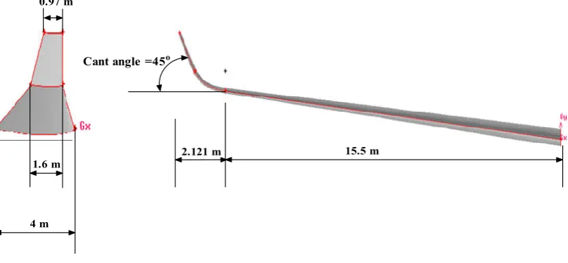
Figure 1-a. Aircraft wing with sharp edge winglet 45 cant angle (Abdelghany et al., 2016)
4 m 1.6 m
0.97 m
Cant angle =45o
[image:2.595.91.495.283.470.2]2.121 m 15.5 m
Figure 1. b. Aircraft wing with blended winglet 45 cant angle (Abdelghany et al., 2016).
Figure 2. Wing control volume mesh
[image:2.595.147.436.530.775.2]Figure 3. lift coefficient ofair stream angle,α=12degreeVS number of grid
Figure 4. The distribution of the Coefficient of lift againstair stream angle(α), for different wing shapes
[image:3.595.118.480.546.774.2](a) Angle of attack 0 de gre e (b) Angle of attack 4 de gre e
(c) Angle of attack 8 degree (d) Angle of attack 12 de gre e
Secondary flow
[image:4.595.93.499.83.421.2](Go from tip to root of wing)
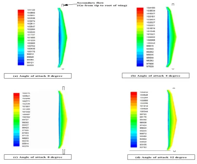
Figure 6a. Wing with sharp edge winglet pressure contours
(a) Angle of attack 0 degre e (b) Angle of attack 4 degree
(c) Angle of attack 8 degre e (d) Angle of attack 12 degree
Se condary flow
[image:4.595.125.467.458.770.2](Go from tip to root of wing)
Figure 6 b. Wing with blended winglet pressure contours
subjected to ambient conditions of 1-bar Pressure and temperature of 288-K at subsonic Mach No of 0.2then solved by FLUENT software using finite volume method. Results obtained are aerodynamics characteristics like lift, Drag at different air stream angle (α), also Path lines on the wing.
Geometry and Grids
Atapered wing with NACA23016airfoil for root wing section, NACA23014 airfoil for mean wing section and, NACA23012 airfoil for tip wing section of A CRJ - 100 aircraft wing are considered. The airfoils are drawn using Gambit with a chord length of 4 m at root section, a chord length of 2.8 m at mean section and a chord length of 1.6 m at tip section.
The wing has a span of 31m. In order to achieve lift and drag on wing, GAMBIT® software is generated mesh, which close to the wing volume should be small enough to satisfy boundary conditions for far field (Abdelghany et al., 2016). Tetrahedral unstructured mesh used for complex shape of winglet. Near to the wing wall size of grid must be small enough to reach to the good results of lift and drag. Figure 2 shows also the grid volumes important used to reduce time of solution and owed memory.
Grid independency check
In general, a numerical result becomes exact by increasing number of cells.
Upper surface of wing with winglet
Lower surface of wing with winglet
[image:5.595.113.490.67.304.2]Sharp edge winglet
Figure 7a. Aircraft semi-span wing with sharp edge winglet pressure contour of a CRJ - 100 with cant angle 45 degree isometric view at Air stream angle, α=12 degree.
Upper surface of wing with winglet
Lower surface of wing with winglet
Blended winglet
[image:5.595.116.488.348.604.2]When the computations running, aimed to save time, the minimum cells number demonstrate grid independency check for the calculations presented. In the present study grid sizes of 0.5*106 to 2*106 by step of 0.5*106 are used and the CL The lift
coefficient at the air stream angle is monitored as shown in figure 3. It is clear for that figure that to be considered. These cases for a grid with around 1,500,000 cells as a reasonable grid size to produce grid independent solution.
RESULTS AND DISCUSSION
In this section the results obtained from CFD calculation for lift coefficient, drag coefficient, path lines and pressure contours around wing at different air stream angles are presented.
Aerodynamic Analysis
Figure 4shows lift coefficient, increase with increase in air stream angle, α. This figure also shows that ,wing with blended winglet has the highest lift coefficient, CL, ranges from 13.6%
to 14.5% with air stream angle comparing with the wing without winglet. The wing with sharp edge winglet gives the next highest lift coefficient, CL, ranges from 10% to 11.6%
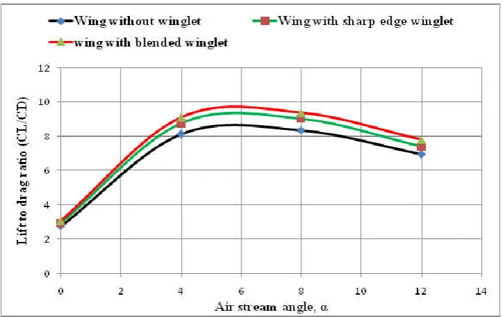
with air stream angle comparing with the wing without winglet. Figure 5shown below; indicates that the wing with blended winglet has maximum lift to drag ratio; CL/CD by
about 11% to 12.4% with different air stream angles comparing with the wing without winglet. Trends is followed by wing with sharp edge winglet, which is the next highest lift to drag ratio where CL/CD range from 6.4% to 8.2 % with
different air stream angles comparing with the wing without winglet.
Reducing trailing vortices Front View
[image:6.595.127.459.274.521.2]Near wing tip
Figure 8a. Wing with sharp edge winglet pathlines at air stream angle, α=12 degree
Reducing trailing vortices Front View
[image:6.595.149.441.572.775.2]Near wing tip
Figure 8b. Wing with blended wingletspathlines in case at air stream angle 12 degree
Pressure Contours
Figure 6shows upper static pressure contours for wing with winglet at cant angle, 45 degree. At air stream angle 0 degree, the minimum static pressure is located at the upper surface. At air stream angle, α=12 degree, the high intensity blue area are located on the upper surface. The figure also shows that the contours of the most of the total force are directed backward as drag. For all air stream angles, the minimum static pressure zones are located at mid of the wing. The figure also shows that minimum pressure value is higher than the minimum pressure value at the root. The r pressure decreases from root to tip, then the pressure increases to reach the atmosphere pressure, so as to reducing vortices at wing tip.
Effects of different winglets with cant angle 45o
Figure 7 show pressure contours on sides of the wing surface with blended winglets, for different angles of attack. These wings with different winglets tested at a subsonic Mach number of 0.2 and ambient conditions pressure of (1 bar) and temperature of (288 K) at sea level.
Pathlines
It is well-kwon that pressure difference between both sides of wing surfaces of makes vortices. When pressure difference increase with increasing of air stream angle then wing vortex is increasing. The wing with blended winglet and wing with sharp edge actually reduce vortices at the wingtip as expected. The rotational motion can be visualized more easily by presented the path lines. The path lines indicate that fluid is moves from lower to upper surface thus creating vortices. .Figure 8shows path lines over the wing with winglet at maximum air stream angle of 12o. Path lines are zoomed in at the wingtip where trailing vortices occurs. Due to the small e in pressure difference between both sides of wing surfaces tip vortices are very small
Conclusion
Winglet designs considerably yield improvement of the aircraft performance and fuel consumption reduction. Effects of blended winglet and sharp edge winglet were investigated using CFD technique. In addition, to comparisons between the blended winglet, sharp edge winglet and the case without winglet. Each case was compared to cases without winglet, with the sharp edge winglet and blended winglet. The wing with winglet blended connection has lift to drag ratio, CL/CD range varies from (11- 12.4) % with different air stream angles more than wing without winglet. The wing model with sharp edge winglet has lift to drag ratio, CL/CD range varies from (6.4- 8.2) % with different air stream angles less than the wing without winglet at air stream angle α= 6 degree.\
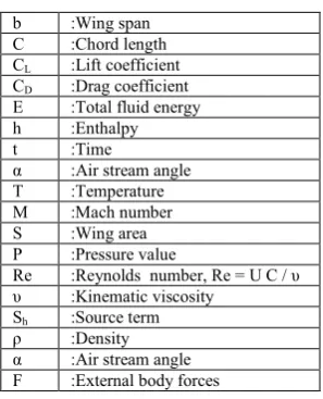
Nomenclature
b :Wing span C :Chord length CL :Lift coefficient
CD :Drag coefficient
E :Total fluid energy h :Enthalpy t :Time
α :Air stream angle T :Temperature M :Mach number S :Wing area P :Pressure value
Re :Reynolds number, Re = U C / υ υ :Kinematic viscosity
Sh :Source term
ρ :Density α :Air stream angle F :External body forces
REFERENCES
Abdelghany, E. S., Khalil, E. E., Abdelatif, O. E. and Elharriry, G. M. 2016. "Aircraft Winglet Design and performance: Cant angle effect", Journal of Robotics and Mechanical Engineering Research, vol. 1, issue 3, pp. 28-34.
Azlin, M. A., Mat Taib, C. F., Kasolang, S and Muhammad, F. H. 2011.“CFD Analysis of Winglets at Low Subsonic Flow”, World Congress on Engineering, Vol. 1, pp. 1-5, 2011.
Bourdin, P., Gatto, A. and Friswell, M.I. 2006. The application of variable cant angle winglets for morphing aircraft control, 24th AIAA Applied Aerodynamics Conference, San Francisco, CA, June 5-8.
FLUENT Documentation. © Fluent Inc. 2005.
Gavrilović Nikola, N., Rašuo Boško, P., Dulikravich George, S., Parezanović Vladimir, B. 2014. ''Commercial Aircraft Performance Improvement Using Winglets, Computational Mechanics'', 6th European Conference on Computational Fluid Dynamics, Barcelona, Spain, July 20-25.
Kubrynski, K. 2003. ''Wing-winglet design methodology for low speed applications'', AIAA paper 03-0215, 41st Aerospace Science Meeting and Exhibit, Reno, NV, January. Minella, G., Ugas, A. and Rodriguez, Y. 2010. Aerodynamic shape design optimization of airplane winglets, Senioryear B.Sc. thesis, MME Dept., Florida International University, Miami, FL, December.
Robert, T., Jones, 1984.“Improving The Efficiency Of Smaller Transport Aircraft”, 14th Congress of the International
Council of the Aeronautical Sciences, Proceedings, Vol. 1, Toulouse, Fr.
Versteeg, H., and Malalasekera, W. 1995. “An Introduction to Computational Fluid Dynamics: The Finite Volume Method” Longman.
Weierman, J. and Jacob, D. 2010. ''Winglet design and optimization for UAVs'', AIAA Applied Aerodynamics Conference, June 28 - July 1.
[image:7.595.359.508.68.252.2]