MODIFIED MAGNETIC FLOAT DENSITOMETER
*Indu Saxena, Anoop Mishra, Vijay Kumar, Sadhana Gautam and Jaya Tripathi
Department of Chemistry, University of Lucknow, Lucknow 226007, India
ARTICLE INFO ABSTRACT
Some major modifications have been introduced in the modified version of Magnetic Float Densitometer; change in the design of float, it had a depression (concave shape) at the upper part, ferrite core inside the
has been changed into auto circuit. These modifications improved the working easier.
Copyright © 2016, Indu Saxenaet al. This is an open access article distributed under the Creative Commons Att distribution, and reproduction in any medium, provided the original work is properly cited.
INTRODUCTION
Magnetic float densitometer is one of the most fascinating instruments to measure the densities of solvents and solutions in today’s modern time. A magnetic float, made of a long cylindrical or a bar magnet and Pyrex glass, floats in the solution, the motion of which may be controlled by either electromagnetic field produced by passing a current in the coil (a solenoid) or by another magnetic field cr
arrangement of some other magnets. The motion of the float is thus related with density of solution, in which, it is floating. A variety of mathematical expressions are forwarded by many scientists4 working in this field. The type of Magnetic F Densitometer which is used in the present investigation is the one in which the magnetic float, floating in the solution, is controlled by electrical circuits. Some scientists called this type of an instrument as Magnetic Float Densimeter, in place of magnetic float densitometer. Basically both have the same sense and meaning.
Basic concepts
If an electric current is passed in a coil in such a way that there is a clockwise circulation of current, seeing the coil from its front end, the front end of the coil becomes South Pole.
*Corresponding author: Indu Saxena,
Department of Chemistry, University of Lucknow, Lucknow 226007, India.
ISSN: 0975-833X
Article History:
Received 10th July, 2016
Received in revised form
22nd August, 2016
Accepted 18th September, 2016
Published online 30th October,2016
Key words:
Magnet, Ferrite core, Circuit diagram, Solenoid, Main coil, Platinum wire and float.
Citation: Indu Saxena, Anoop Mishra, Vijay Kumar, Sadhana Gautam and Jaya Tripathi
Journal of Current Research, 8, (10), 39800-39812.
RESEARCH ARTICLE
MODIFIED MAGNETIC FLOAT DENSITOMETER
Indu Saxena, Anoop Mishra, Vijay Kumar, Sadhana Gautam and Jaya Tripathi
Chemistry, University of Lucknow, Lucknow 226007, India
ABSTRACT
Some major modifications have been introduced in the modified version of Magnetic Float Densitometer; change in the design of float, it had a depression (concave shape) at the upper part, ferrite core inside the solid cylinder concentric to coils and cylinder itself is used, electrical circuitry has been changed into auto circuit. These modifications improved the working easier.
is an open access article distributed under the Creative Commons Attribution License, which distribution, and reproduction in any medium, provided the original work is properly cited.
Magnetic float densitometer is one of the most fascinating instruments to measure the densities of solvents and solutions magnetic float, made of a long cylindrical or a bar magnet and Pyrex glass, floats in the solution, the motion of which may be controlled by either electromagnetic field produced by passing a current in the coil (a solenoid) or by another magnetic field created by an arrangement of some other magnets. The motion of the float is thus related with density of solution, in which, it is floating. A variety of mathematical expressions are forwarded by many The type of Magnetic Float Densitometer which is used in the present investigation is the one in which the magnetic float, floating in the solution, is controlled by electrical circuits. Some scientists called this type of an instrument as Magnetic Float Densimeter, in place magnetic float densitometer. Basically both have the same
If an electric current is passed in a coil in such a way that there is a clockwise circulation of current, seeing the coil from its
the coil becomes South Pole.
Department of Chemistry, University of Lucknow, Lucknow 226007,
If the north pole of the magnet, which is free to move, is brought near this coil, a force of attraction is
between the two. If the coil is fixed and the magnet is let free above this coil then the magnet starts moving down ward towards the coil due to the attraction force Figure 1 (a). Similarly, if the current flows in coil in anticlockwise direction, as seen the front end of the coil becomes North Pole. Now if a south pole of the magnet is brought near the fixed coil, the magnet gets attracted towards it and starts moving down ward as shown in Figure 1(b).
Magnetic field due to a solenoid carrying e
If, I current is flowing in a solenoid the magnetic field ‘M’ is developed inside the coil, if the number of turns of coil is ‘n’ then, H = 4nI, H = Magnetic field intensity. This field is produced in the form of magnetic lines of forc
parallel to the solenoid entering from one end and exiting out from the other end. In case, the solenoid has a core of magnetic material of permeability µ, then
B = µ x 4 π n I gauss
Where, B = magnetic induction / unit area (or magnetic flux density)
This leads to the concentration of magnetic lines of force and formation of strong magnetic poles at the ends of coil.
International Journal of Current Research
Vol. 8, Issue, 10, pp.39800-39804 October, 2016
INTERNATIONAL
Indu Saxena, Anoop Mishra, Vijay Kumar, Sadhana Gautam and Jaya Tripathi, 2016. “Modified magnetic float densitometer
Indu Saxena, Anoop Mishra, Vijay Kumar, Sadhana Gautam and Jaya Tripathi
Chemistry, University of Lucknow, Lucknow 226007, India
Some major modifications have been introduced in the modified version of Magnetic Float Densitometer; change in the design of float, it had a depression (concave shape) at the upper part, solid cylinder concentric to coils and cylinder itself is used, electrical circuitry has been changed into auto circuit. These modifications improved the working easier.
ribution License, which permits unrestricted use,
If the north pole of the magnet, which is free to move, is brought near this coil, a force of attraction is developed between the two. If the coil is fixed and the magnet is let free above this coil then the magnet starts moving down ward towards the coil due to the attraction force Figure 1 (a). Similarly, if the current flows in coil in anticlockwise , as seen the front end of the coil becomes North Pole. Now if a south pole of the magnet is brought near the fixed coil, the magnet gets attracted towards it and starts moving down ward as shown in Figure 1(b).
Magnetic field due to a solenoid carrying electric current, I
If, I current is flowing in a solenoid the magnetic field ‘M’ is developed inside the coil, if the number of turns of coil is ‘n’ then, H = 4nI, H = Magnetic field intensity. This field is produced in the form of magnetic lines of forces extending parallel to the solenoid entering from one end and exiting out In case, the solenoid has a core of magnetic material of permeability µ, then
B = µ x 4 π n I gauss (1)
Where, B = magnetic induction / unit area (or magnetic flux
This leads to the concentration of magnetic lines of force and formation of strong magnetic poles at the ends of coil. Thus to
INTERNATIONAL JOURNAL OF CURRENT RESEARCH
enhance the force of attraction further, a ferrite core is used inside the coil. The action of ferrite core is to concentrate the lines of force inside the coil which leads to a stronger pole (north or south) at the front end of the coil shown in (Figure 2).
Figure 1 (a). Showing the movement of the magnet when the current is clockwise in the coil
Figure 1 (b). Showing the movement of the magnet when the current is anti - clockwise in the coil
Arrangement of either fig. 1(a) 1(b) may be employed in the Magnetic Float Densitometer. If the magnitude of the current is controlled in the coil by external means, then the up and down motion of the free magnet is regulated. The magnet is housed in a Pyrex glass in the form of float. Thus the magnet along with float moves up and down depending upon the magnitude of the current in the coil. This is how the Magnetic Float Densitometer works2. Sometimes it happens that the float is at a considerably long distance from the main solenoid and the main solenoid unable to attract the magnet of the float to bring it down to the bottom of the solution container. In that case, a
[image:2.595.42.284.110.333.2]helping coil, called the pull down solenoid, is used between the magnetic float and the main solenoid as shown in figure 3. Its main purpose is to bring the float in the region of main solenoid. When main solenoid takes control over it, the function of pull down solenoid finishes out. Now the current is stopped in the pull down solenoid and only the main solenoid functions for recording the observations.
[image:2.595.331.540.151.352.2]Figure 2. Concentration of magnetic lines of force due to Ferrite Core
Figure 3. Relative arrangement of main coil, helping coil and float
[image:2.595.307.554.371.712.2] [image:2.595.41.286.371.631.2]Construction and circuit descriptions
The diagram of his Magnetic Float Densitometer is shown in figure 4. The densitometer consists of the following major components:
The solution container,
The magnetic float,
The pull down solenoid,
The main solenoid &
The support and leveling platform.
The float and solution container were made of Pyrex glass, and the support and leveling platform of brass.
Figure 4. Sketch of Millero’s Magnetic Float Densitometer
The magnetic float B was made of Pyrex glass
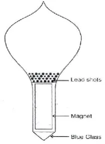
[image:3.595.310.557.227.406.2]volume of 32.37865 ml at 298.15K. The density of the float (0.958564 g/ml) was adjusted by adding lead shots before sealing. The float contained a magnet inside it which was held in place by sealing wax. The top of the float had a slight extension to support a bridle that holds the weight on the float is shown in Figure 5.
Figure 5. Magnetic Float as was used by Millero
A small amount of blue glass was fused at the bottom of the float to make it easier to determine when the float touched the bottom of the solution container. A magnifying lens was used to see the float’s movements i.e. when the float touched and The diagram of his Magnetic Float Densitometer is shown in figure 4. The densitometer consists of the following major
The float and solution container were made of Pyrex glass, and
o’s Magnetic Float Densitometer
The magnetic float B was made of Pyrex glass and had a volume of 32.37865 ml at 298.15K. The density of the float (0.958564 g/ml) was adjusted by adding lead shots before sealing. The float contained a magnet inside it which was held in place by sealing wax. The top of the float had a slight n to support a bridle that holds the weight on the float
ic Float as was used by Millero
A small amount of blue glass was fused at the bottom of the float to make it easier to determine when the float touched the bottom of the solution container. A magnifying lens was used when the float touched and
when it is lifted off from the bottom of the solution container. The pull down solenoid C, which is fixed on a solid brass support, was used to bring the float into the field of main solenoid. The main solenoid D was used to adjust the buoyancy force of the float, that is, only this solenoid worked at the time of taking the observations. The support had a hole drilled into it to hold the solution container. At the bottom of the hole, there was a window for viewing the float when it rested on the bottom of solution container. The leads of both the solenoids were taken out through
whole instrument was kept in a thermosta
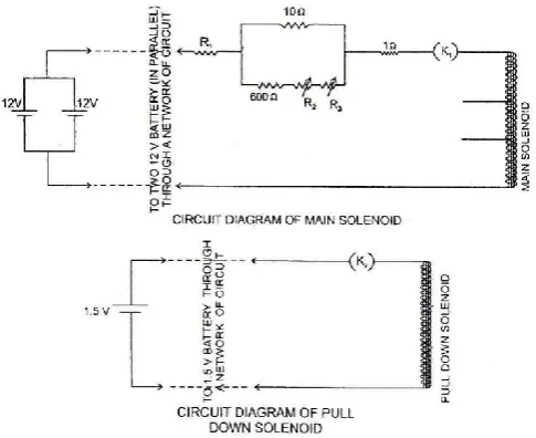
desired temperature of the solution. Circuit diagrams used by Millero for Main and Pull down solenoids are shown in Figure 6.
Figure 6. Circuit diagram of main and pull down solenoids used by Millero
Components used
Two 12V batteries in parallel, one 1.5V battery, NBS standard 1Ω resistor, P, a Hewlett-Packard Differential voltmeter, R to 10, 000 Ω decade resistance box R
0 to 100 Ω ten turn berg pots. These berg pots were used to make final adjustment. For calibrating the instrument with distilled water at 298.15 K Millero used following equation
W = - [f /1-dwater/dpt)] × I + [dwater V
(Which is in the form y = mx + c)
A graph between the weights w, and
was plotted and the Magnetic Float Densitometer parameters were calculated as,
f=3.5308g/A, V=32.32865ml
Then density of solvents and solutions were calculated by using following equation,
D = (W + w + f×I)/ (V + w /dpt) (3)
The weight equivalent current factor ‘f’ of the Magnetic Float Densitometer is very important in the versatility of the instrument. The value of this factor can be changed by changing the strength of the electromagnetic force of solenoid. This can be done by putting a choice of using different number of turns of main solenoid. Thus the sensitivity of the when it is lifted off from the bottom of the solution container. The pull down solenoid C, which is fixed on a solid brass s used to bring the float into the field of main solenoid. The main solenoid D was used to adjust the buoyancy force of the float, that is, only this solenoid worked at the time of taking the observations. The support had a hole solution container. At the bottom of the hole, there was a window for viewing the float when it rested on the bottom of solution container. The leads of both the solenoids were taken out through a Tygon Tubing. The whole instrument was kept in a thermostat to maintain at a desired temperature of the solution. Circuit diagrams used by Millero for Main and Pull down solenoids are shown in
Figure 6. Circuit diagram of main and pull down solenoids used by Millero
12V batteries in parallel, one 1.5V battery, NBS standard Packard Differential voltmeter, R1, 0
Ω decade resistance box R2 and R3, 0 to 2000 Ω and
Ω ten turn berg pots. These berg pots were used to For calibrating the instrument with distilled water at 298.15 K Millero used following equation
water V-W/(1- dwater/dpt ) (2)
(Which is in the form y = mx + c)
A graph between the weights w, and the hold down current, I, was plotted and the Magnetic Float Densitometer parameters
Then density of solvents and solutions were calculated by
) (3)
[image:3.595.111.216.591.734.2]instrument can be adjusted. Millero used three choices 700, 200 and 100 number of turns in the main solenoid for varying the sensitivity.
First improvement in the model
The Millero’s model of Magnetic Float Densitometer was modified in our laboratory by making five changes in the design. These modifications were-
Blue fused glass was replaced by a platinum wire, sharply pointed at one end, at the bottom of the float,
Light focusing arrangement was introduced to add in view of the platinum point, instead of using magnifying glass only,
A modified electrical circuitry has been incorporated in the design,
A ferrite core inside the solid cylinder concentric to the coils and cylinder itself was used &
A slight change was made in the design of upper part of the Float. It had a depression (concave shape) in the upper part so that the weights could conveniently be put on it.
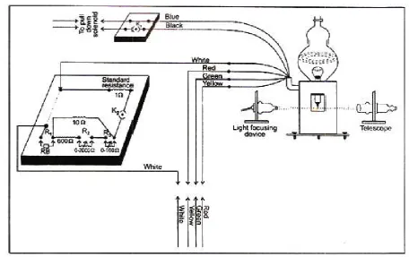
[image:4.595.310.555.51.222.2]However for the sake of continuity of our investigation, we are giving few details of the model in brief. In this modified model, the lower end of the float was fused with the pointed platinum wire. A telescope was used to view the movement of float when its platinum point touched the bottom of solution container. To assist the observation a light focusing device opposite to the telescope was used. A focused light was made to fall on the glass window and the platinum point which was viewed from the opposite direction by telescope. To increase the efficiency of the coil a ferrite core was introduced at the center of the brass support; the upper part of this ferrite core was surrounded by pull down solenoid and the lower part, by main solenoid. The ferrite core concentrates the magnetic lines of force at the center and thus provides sufficient magnetic attraction on the float. The Millero’s circuits of solenoid were replaced by following circuits shown in figure 7, 8 (a), 8 (b) and 8 (c) for operating the currents in pull down and main solenoids by push-buttons.
Figure 7. Circuit diagram of main solenoid and pull down solenoid
Figure 8 (a). Complete electrical circuit of Magnetic Float Densitometer (Stage-I)
Figure 8 (b). Complete electrical circuit of Magnetic Float Densitometer (Stage-II)
Figure 8 (c). Complete electrical circuit of Magnetic Float Densitometer (Stage-III)
[image:4.595.310.553.261.434.2] [image:4.595.308.556.473.649.2] [image:4.595.42.285.552.750.2]Experimental
The system was calibrated with pure water at 298.15 K by measuring the hold down current I, when various
were added to the float in the following manner.
water was taken in the solution container. The system was kept in Toshiwal constant temperature bath to maintain the temperature of solution at 298.15K. The weights, w, were added to the float and the corresponding hold down current, I, was measured by the following method. Referring figure. 8 (a), 8(b) and (c)-The keys k1 and k2 were kept closed. The number
of turns in the main solenoid was selected by the right hand section of push buttons. In this section, if push button no. 3 is pressed then 700 numbers of turns are selected. The battery operation was performed by push button section in the extreme left hand side of the circuit diagram. If push button no.2 is pressed in this section then both the batteries are simultaneously switched on. Now the middle section of circuit was operated. This section controls the operation of both the coils. By pressing push button no. 1 pull down solenoid is ‘on’.Pressing of push button no. 2 makes both the coils ‘on’ and push-button no. 3 breaks the circuit of pull down solenoid and only main solenoid remains ‘on’. The observations are taken at push button no.3 pressed down. The process is explained in three stages shown by Figs.8 (a), 8(b) & 8(c). resistance bridge was adjusted by selecting the proper values of different resistance, R1 R2 R3 so that the float just touched
the bottom of the solution container. This was viewed by telescope and light focusing arrangement. The reading of the voltage drop (in terms milli-volts) across 1
[image:5.595.67.524.53.340.2]resistance was taken by multimeter. Since the resistance value is1Ω, this directly gives the magnitude of the current in mA (V = RI & R = 1Ω). A graph is plotted between the weights w, and the corresponding hold down currents I.
Figure 9. The laboratory set up for operation of
The system was calibrated with pure water at 298.15 K by measuring the hold down current I, when various weights, w, were added to the float in the following manner. The distilled water was taken in the solution container. The system was kept in Toshiwal constant temperature bath to maintain the temperature of solution at 298.15K. The weights, w, were to the float and the corresponding hold down current, I, Referring figure. 8 (a), were kept closed. The number of turns in the main solenoid was selected by the right hand h buttons. In this section, if push button no. 3 is pressed then 700 numbers of turns are selected. The battery operation was performed by push button section in the extreme left hand side of the circuit diagram. If push button no.2 is ion then both the batteries are simultaneously switched on. Now the middle section of circuit was operated. This section controls the operation of both the coils. By pressing push button no. 1 pull down solenoid is both the coils ‘on’ button no. 3 breaks the circuit of pull down solenoid and only main solenoid remains ‘on’. The observations are taken at push button no.3 pressed down. The process is explained in three stages shown by Figs.8 (a), 8(b) & 8(c). The resistance bridge was adjusted by selecting the proper values so that the float just touched the bottom of the solution container. This was viewed by telescope and light focusing arrangement. The reading of the volts) across 1Ω standard resistance was taken by multimeter. Since the resistance value Ω, this directly gives the magnitude of the current in mA (V A graph is plotted between the weights w,
Using the known value of density of water and density of platinum, the parameters, as mentioned above, were calculated at 298.15K. The densitometer was run in the solution of unknown density. The observations were taken as before. Various weights, w, and corresponding hold down currents, I, were noted. The densities of solvents and solutions were then calculated by using equation.
D = (W+w+f × I) / (V+ w /dpt)
This modified model of Magnetic Float Densitometer makes the operation easier and efficient. The cost of the instrument was also drastically cut down due to cheaper electronic components used.
Acknowledgement
The author thanks to the Head of the Chemistry Department, Lucknow University for providing the research facility in the Department.
REFERENCES
Dorsey, N. E. 1940. Properties of ordinary water substances ACS Monograph No 81, Reinhold Publishing Corporation, New York.
Millero, F. 1967. J., Rev. Sci. Instr.,
Pathak, R. N. and Saxena, I., 1998. 278.
Spedding, F. H., Pikal M. J. and Ayers B. O. 1966.
Chem. 70, 2440.
The laboratory set up for operation of the Magnetic Float Densitometer
*******
Using the known value of density of water and density of platinum, the parameters, as mentioned above, were calculated at 298.15K. The densitometer was run in the solution of The observations were taken as before. Various weights, w, and corresponding hold down currents, I, were noted. The densities of solvents and solutions were then
) (4)
This modified model of Magnetic Float Densitometer makes the operation easier and efficient. The cost of the instrument was also drastically cut down due to cheaper electronic
ead of the Chemistry Department, Lucknow University for providing the research facility in the
Properties of ordinary water substances ACS Monograph No 81, Reinhold Publishing Corporation,
J., Rev. Sci. Instr., 38, 1441.
1998. Indian J. Eng. Mat. Sci., 5,
and Ayers B. O. 1966. J. phys.