Control Plane Handoff Analysis for IP Mobility
Ditchaphong Phoomikiattisak
Geo-Informatics and Space Technology Development Agency Bangkok, Thailand
Email: [email protected]
Saleem N. Bhatti
School of Computer Science University of St Andrews, UK Email: [email protected]
Abstract—Seamless host mobility is vital to future network mobility, and has been an active research area for a long time. Much research focuses on the performance of thedata plane. In this paper, we present comprehensive analyses on the control (signalling) plane in the IETF Mobile IPv6, and compare it with the IRTF Identifier-Locator Network Protocol (ILNP). The control plane behaviour is important in order to assess the robustness and scalability of the mobility protocol. ILNP has a different mobility model from Mobile IPv6: it is a host-based, end-to-end architecture and does not require additional network-layer entities. Hence, the control signals are exchanged only between the end systems. We provide model-based analyses for handoff signalling, and show that ILNP is more efficient than MIPv6 in terms of robustness and scalability. The analytical models we present could also be adapted for other mobility solutions, for comparative assessment.
I. INTRODUCTION
Mobility management has been an active research area for several decades, and a number of mobility solutions have been introduced. Most studies focus on performance in the data plane, e.g. how to minimise packet loss and interruption time during a mobile node (MN) handoff. However, in some sce-narios, such as satellite networks and mobile ad hoc networks (MANETS), overall bandwidth usage is significant, and so it is important to consider the control plane traffic as well as data plane traffic for a complete assessment. Hence, mobility support for such networks not only requires a smooth handoff in thedata plane, but also needs a robust and scalable approach with minimum signalling overhead in the control plane.
The IETF Mobile IP (MIP) solution is widely accepted as the standard approach for IP mobility for both IPv4 (MIPv4) [1] and IPv6 (MIPv6) [2]. Mobile IP allows an MN to have two IP addresses: a home address (HoA), which acts as an
identifierfor the MN, and Care-of-Address (CoA), which acts as a locator for the MN. Mobility management is achieved by mapping between these two IP addresses using a Home Agent (HA) and a Foreign Agent (FA). The latter is required only for MIPv4 and is not necessary for MIPv6. MIPv4 uses tunnelling between HA and FA, while MIPv6 introduces a Route Optimisation (RO) mechanism to eliminate tunnelling and avoid sub-optimal packet routes. This paper considers only the case of MIPv6.
The Identifier-Locator Network Protocol (ILNP) [3]–[10] is an IRTF Experimental protocol. ILNP replaces the use of IP addresses by Node Identifier (NID) and Locator (L64)
to enable mobility support and other functionalities. That is, ILNP explicitly and cleanly recognises locator and identifier semantics, whilst in MIP, these are implicit. With a host-based, end-to-end architecture, ILNP can be implemented in
the end-system stacks as a superset of IPv6, which is called
ILNPv6 [6]–[9]. ILNPv6 uses the current IPv6 packet header format, and so remains backwards compatible with the current deployed IPv6 routing infrastructure.
A. Contribution and structure of this paper
We present a comparative analysis of handoff signalling for MIPv6, which is considered to be a standard solution for IP mobility, and ILNP, an end-to-end approach to mobility. We analyse two factors related to signalling overhead: scalability
androbustness. For scalability, we consider how the signalling overhead increases as the number of mobile nodes increases. For robustness, we consider the probability of successful handoffs in the presence of loss in the control plane. Our key finding is that an end-to-end model, as used in ILNP, will be more scalable and more robust in nearly all cases.
Our analysis is model based on the protocol operation of both MIPv6 (with and without route optimisation) and ILNPv6, but the approach can be applied to other mobility so-lutions. We only consider handoff performance at the network (IP) layer, as this is the most appropriate for internetworking scenarios, including for vertical handoff scenarios.
Some related work is described in Section II. Then, we give an overview of respective handoff signalling protocols for MIPv6 and ILNP in Section III. We present our analysis for scalability and robustness in Section IV and Section V respectively. After a discussion of some key issues in Section VI, we conclude in Section VII.
II. RELATEDWORK
A. Mobility Solutions
We present here a selection of mobility solutions, mainly on proposals that have been reviewed by the IETF or the IRTF. RFC6301 [11] provides a more comprehensive list of mobility solutions. There are many extensions to the IETF MIPv4 and MIPv6 proposal, optimising various aspects of mobility management, and these are explained briefly below. In general, each of these extensions adds additional complexity and signalling overhead to the base MIP protocol.
Hierarchical Mobile IPv6 (HMIPv6) [12] aims to reduce the handoff delay of MIPv6. A Mobility Anchor Point (MAP) is introduced to manage local mobility. However, additional signalling is required to/from the MAP.
Fast Handover for Mobile IPv6 (FMIPv6) [13] uses IP tunnelling between the Previous Access Router (PAR) and the New Access Router (NAR) to minimise gratuitous packet
loss during handoff [14]. There is additional complexity and overhead due to the extra signalling required to allow use of NAR and PAR.
Proxy Mobile IPv6 (PMIPv6)[15] extends MIPv6 to be a complete network-based solution (MNs do not participate in mobility management). A Mobile Access Gateway (MAG) and a Local Mobility Anchor (LMA) are introduced for this. Extra signalling is also used.
Distributed Mobility Management (DMM) [16], [17] ex-tends the IETF standard protocols, i.e. the Mobile IP family to minimise the issues about routing performance and single point of failure. However, the work has yet to reach a suitable level of maturity.
There are also various Locator/Identifier approaches pro-posed, each with their own support for mobility in various forms.
The Locator Identifier Separation Protocol (LISP) [18] relies on a mapping system to map an IP address into two different schemas (which act as identifier and locator for MNs). LISP was originally designed for multihoming, but latterly, extensions for mobility support have been proposed: LISP mobile node (LISP-MN) [19] and LISP-ROAM [20]. However, these rely on additional signalling.
Level 3 Multihoming Shim Protocol for IPv6 (SHIM6)[21] is another multihoming solution that could be adapted for mobility [22]. However, there is a performance problem in high handoff latency. SHIM6 separates identifier and locator from a single IP address using an extra ‘shim’ layer between the network and the transport layer.
The Host Identity Protocol (HIP) [23], [24] (recently up-dated to HIPv2 [25]) requires the use of public key infrastruc-ture for mobility/multihoming management. The public key acts as the identifier of the MN (i.e. used for session binding), while the IP address is the locator (i.e. used for routing). HIP also recommends the use of additional network entities and requires additional signalling for mobility.
B. Overhead Analysis for Mobility Solutions
There are a number of analyses for Mobile IP and other mobility solutions. However, most of them do not examine scalability and robustness. For example, [26] provides com-prehensive analyses of the MIPv6 family, including some indication of signalling overhead cost, but the paper focus on other performance metrics such as the handoff latency. There is also previous work [27] that presents handoff signalling used by Mobile IP, Session Initiation Protocol (SIP) [28], and Stream Control Transmission Protocol (SCTP) [29]. However, again, the focus is on flow performance in the data plane.
There is also previous scalability analysis of ILNP [30]. However, the paper considers only the case of specific mobile network scenario (London underground rail network) in com-parison to the IETF Network Mobility (NEMO) [31] proposal. There is no examination of mobility for individual hosts.
C. Previous work on Host Mobility Using ILNP
The use of ILNP for host mobility is outlined in [4], [32], [33]. Later on, an ILNP overlay emulation was created for
a feasibility study [34]. The first ILNP mobility prototype in Linux is presented in [35], along with a simple evaluation in the data plane. A comprehensive performance evaluation of the data plane prototype using a legacy UDP application over wireless network was carried out later on [36].
In this paper, we present the first detailed analyses of
control plane of MIPv6 in comparison to ILNPv6, rather than analysis for just the data plane. We provide models for scalability and robustness analysis, which could also be adapted for other mobility solutions.
III. OVERVIEW OFSIGNALLINGPROTOCOLS
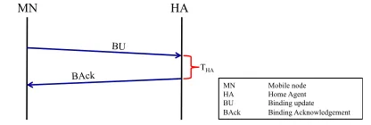
For MIPv6, when an mobile node (MN) performs handoff, signalling is needed for updating the CoA of the MN, so that subsequent data packets can be delivered to the correct location. Figure 1 shows the control signals used for handoff management for MIPv6 when Route Optimisation (RO) is disabled. There are only two control signals required: i) Binding Update (BU) from the MN to the HA to inform a change of the CoA; and ii) BAck sent back from the HA to the MN after the BU has been processed. In the figure, THA
denotes the processing time at the HA.
MN HA
BU
BAck THA
[image:2.612.339.547.325.395.2]MN Mobile node HA Home Agent BU Binding update BAck Binding Acknowledgement
Fig. 1. Control signals during an MN handoff for MIPv6 without RO.
If RO is enabled, there are additional control signals as shown in Figure 2, including:
• Home Test Init (HoTI)andHome Test (HoT)for testing the reachability of the HoA from the CN.TH oT is the
processing time of HoT at the CN, both HoTI and HoT must go through the HA.
• Care-of Test Init (CoTI) and Care-of Test (CoT) for testing that the new CoA of the MN is reachable from the CN.TCoT is the processing time of CoT at the CN.
• BU and BAck between the MN and the CN to update the CoA.TCN is the processing time of a BU at the CN.
MN HA CN
BU
BAck
BU
BAck HoT
HoT CoTI
CoT
HoTI HoTI
THA
THoT
TCN TCoT
MN Mobile node
HA Home Agent
CN Correspondent Node BU Binding update BAck Binding Acknowledgement HoTI Home Test Init HoT Home Test CoTI Care-of Test Init CoT Care-of Test
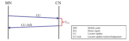
[image:2.612.333.561.493.713.2]For ILNPv6, when an MN performs handoff, signalling is needed for updating the L64 value of the MN. As shown in Figure 3, ILNPv6 uses only 2 packets for handoff signalling: LU and LU-ACK. The signalling packets go directly between the MN and the CN to update the value of L64 of the MN.
TCN is the processing time of the LU at the CN.
MN CN
LU
LU-Ack TCN
[image:3.612.63.284.134.205.2]MN Mobile node HA Home Agent LU Locator update LU-Ack Locator update Acknowledgement
Fig. 3. Control signals during an MN handoff for ILNPv6.
In a real network, the MN may also update the L64 value to the DNS. However, this process is not included in our analyses because it is not always necessary for an MN. A DNS update is required only if the MN expects incoming sessions (i.e. it is a mobile server), which is uncommon today. Moreover, some ap-plications do not rely on DNS: for example, Skype uses a peer-to-peer model, and has its own application-level presence and resolver mechanism [37]. Of course, if specific application-level integration was required, further studies would be needed for integrating ILNPv6 with application-specific rendezvous
services (DNS and other specific services), as well as analyses of the control signals used.
Overall, ILNPv6 handoff signalling overhead is of the same order as MIPv6 without RO. However, as widely known, MIPv6 has a performance problem, due totriangular routing, if RO is disabled. So, it is recommended that RO is enabled for MIPv6, which introduces additional overhead.
IV. SCALABILITYANALYSIS
This section provides analyses of the impact of using MIPv6 (with and without RO) and ILNPv6 as the number of MNs increases. The analyses show how large is the signalling overhead introduced into the network when the number of MNs and CNs increases for a singlehandoff. This measured in terms of number of packets and number of bytes. The number of packets is considered because it affects the pro-cessing and forwarding decision at the routers as well as the packet processing at the end systems (forwarding decisions are per-packet). The number of bytes is considered due to the impact on network capacity and processing power at the end systems (transmission cost is per byte, especially important for mobile systems or satellite systems when considering power consumption).
A. Overhead Calculation
According to Figure 1, MIPv6 without RO has only BU to the HA and BAck from the HA as overhead.
Overhead=BUHA+BAckHA (1)
When the number of MNs increases, that overhead is multi-plied. However, an increase in the number of CNs does not affect the overhead since there are no control signals that go to or from the CN.
Overhead=MN·(BUHA+BAckHA) (2)
Therefore the overhead asnumber of packets is:
OverheadP =2·MN (3)
The packet size of BU and BAck is obtained from atcpdump
log from our previous experiments [36]: BUHA = 110 bytes, BAckHA = 94 bytes. So, thenumber of bytesas overhead is calculated by:
OverheadB =MN·(110+94) =204·MN (4)
From Figure 2, when RO is used, MIPv6 has extra signalling overhead, in addition to BU to the HA and BAck from the HA.
Overhead=BUHA+BAckHA+H oT I+H oT+
CoT I+CoT+BUCN+BAckCN
(5)
Like MIPv6 without RO, that overhead is multiplied when the number of MNs increases. An increase in the number of CNs also affects the overhead signals for the RO process (i.e. HoTI, HoT, CoTI, CoT, BU to CN, and BAck from CN).
Overhead=MN·[BUHA+BAckHA+
CN ·(H oT I+H oT +CoT I+CoT+ BUCN+BAckCN)]
(6)
So, the overhead as number of packetsis:
OverheadP=MN·(2+6·CN) (7)
Again, from our tcpdump logs from our previous experiment [36], the packet size of all signalling packets is obtained:
BUHA,HoTI,BUCN,BAckCN = 110 bytes, BAckHA = 94 bytes, HoT = 118 bytes,CoTI = 70 bytes,CoT = 78 bytes.
So, the number of bytesas overhead is calculated by: OverheadB =MN·(204+596·CN) (8)
The signalling overhead of ILNPv6 is due only to the LU / LU-ACK handshake, as shown in Figure 3.
Overhead=LU+LU-ACK (9)
Increased numbers of MNs and CNs each impact the signalling overhead because they are both involved in the handshake.
Overhead=MN·CN ·(LU+LU-ACK) (10)
So, the overhead as number of packetsis:
OverheadP =2·MN·CN (11)
The sizes of LU and LU-ACK packets, again, are retrieved from the tcpdump logs from our previous experiment [36],
LU =LU-ACK = 86 bytes, so:
OverheadB =172·MN·CN (12)
B. Results
In our analyses, the number of MNs and the number of CNs are scaled from 1 to 100, and we consider a ‘full matrix’ communication scenario, where all CNs are communicating with all MNs. That is the number of communication sessions is a direct product of the number of MNs and number of CNs. Of course, for higher number of MNs and CNs, the same equations can also be applied. By replacing the numbers in the equations listed above, the number of signalling packets and the overhead in bytes are calculated.
Number of signalling packets used
0 20 40 60 80 100 Number of MN
0 20 40 60 80 100
Number of CN
0 50 100 150 200
(a) MIPv6 without RO (detailed scale).
Number of signalling packets used
0 20 40 60 80 100 Number of MN
0 20 40 60 80 100
Number of CN
0 10000 20000 30000 40000 50000
(b) MIPv6 without RO.
Number of signalling packets used
0 20 40 60 80 100 Number of MN
0 20 40 60 80 100
Number of CN
0 10000 20000 30000 40000 50000
(c) MIPv6 with RO.
Number of signalling packets used
0 20 40 60 80 100 Number of MN
0 20 40 60 80 100
Number of CN
0 10000 20000 30000 40000 50000
[image:4.612.103.249.65.158.2](d) ILNPv6.
Fig. 4. Packet overhead. ILNPv6 has a much lower packet overhead compared to MIPv6 with RO. MIPv6 without RO yields the lowest packet overhead, and increases only when the number of MNs increases. (Darker colours are better.)
a very low overhead compared to the other two cases because an increase in the number of CNs does not affect the overhead, only an increase in the number of MNs does, as shown in Figure 4a. Only around 200 overhead packets are introduced into the network for 100 MNs. Nevertheless, ILNPv6 still has relatively low packet overhead compared to MIPv6 with RO. For 100 MNs each of which has 100 associated CNs, ILNPv6 produces around 20,000 extra packets, which is less than half
Number of bytes added to network
0 20 40 60 80 100 Number of MN
0 20 40 60 80 100
Number of CN
0 5000 10000 15000 20000
(a) MIPv6 without RO (detailed scale).
Number of bytes added to network
0 20 40 60 80 100 Number of MN
0 20 40 60 80 100
Number of CN
0 500000 1e+06 1.5e+06 2e+06 2.5e+06 3e+06 3.5e+06 4e+06
(b) MIPv6 without RO.
Number of bytes added to network
0 20 40 60 80 100 Number of MN
0 20 40 60 80 100
Number of CN
0 500000 1e+06 1.5e+06 2e+06 2.5e+06 3e+06 3.5e+06 4e+06
(c) MIPv6 with RO.
Number of bytes added to network
0 20 40 60 80 100 Number of MN
0 20 40 60 80 100
Number of CN
0 500000 1e+06 1.5e+06 2e+06 2.5e+06 3e+06 3.5e+06 4e+06
[image:4.612.373.523.66.159.2](d) ILNPv6.
Fig. 5. Byte overhead. ILNPv6 has a much lower byte overhead compared
to MIPv6 with RO. MIPv6 without RO yields the lowest byte overhead, and increases only when the number of MNs increases. (Darker colours are better.)
of overhead packets of MIPv6 with RO (50,000 packets).
[image:4.612.99.257.94.593.2] [image:4.612.369.527.184.587.2]compared to MIPv6 with RO. For 100 MNs (each of which has 100 CNs), ILNPv6 generates around 1.5 Mbytes of overhead into the network compared to 4 Mbytes overhead for MIPv6 with RO.
V. ROBUSTNESSANALYSIS
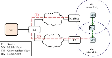
We analyse how lossy network paths impact the handoff success rate. We use a simple network topology, as shown in Figure 6, for this analysis. We consider path loss rate (1) between HA and R1, the old link before the MN handoff, and (2) between MN and R1 through R3, the new link after the MN handoff. We consider there is no packet loss between R1 and CN. This is just an example case to study the impact of an indicative loss at certain points in the network. There are more scenarios in the real Internet, for example, a shorter path to the HA, or lossy CN-R1 link. Further investigation in an
operational scenariowould be required to provide an absolute result under different circumstances.
R1
CN
site network L3 R3
site network L2
R2 (HA)
R Router MN Mobile Node CN Correspondent Node HA Home Agent
MN
MN
MN (1)
(2)
Fig. 6. Topology for signalling analysis. We consider combinations of packet loss rates as path loss, show in red/dashed line, (1) between HA and R1, and (2) between MN and R1 through R3.
A. Handoff Success Rate Calculation
According to Figure 1 - 3, the handoff is completed when all signalling packets successfully reach the destination.
PX denotes the probability of the success of X. So, for
MIPv6 without RO, the probability that a handoff is successful (PMIPnRO) is the probability that a BU to the HA is successful
(PBUHA) and probability that a BAck from HA is successful
(PBAckHA). Note that we assume thatPBUHA andPBAckHA are
independent.
PMIPnRO=PBUHA·PBAckHA (13)
Likewise, the probability that a handoff is successful for MIPv6 with RO (PMIPwRO) is the probability that all con-trol signals are successfully exchanged, including BU to HA (PBUHA), BAck from HA (PBAckHA), HoTI (PHoTI), HoT
(PHoT), CoTI (PCoTI), CoT (PCoT), BU to CN (PBUCN),
and BAck from CN (PBAckCN). Again, the probabilities of
successful packet exchanges are assumed to be independent.
PMIPwRO =PBUHA·PBAckHA·PHoTI·PHoT
·PCoTI·PCoT·PBUCN·PBAckCN
(14)
Finally, the probability that a handoff is successful for ILNPv6 (PILNP) is the probability that LU is successfully received
(PLU) and the probability that LU-ACK is successfully
re-ceived (PLU-ACK).PLU andPLU-ACK are also assumed to
be independent.
PILNP=PLU ·PLU-ACK (15)
R1
CN
site network L3 R3
site network L2
R2 (HA)
R Router MN Mobile Node CN Correspondent Node HA Home Agent
MN
MN
MN BU
BAck Movement
(a) BU/BAck to/from HA.
R1
CN
site network L3 R3
site network L2
R2 (HA)
R Router MN Mobile Node CN Correspondent Node HA Home Agent
MN
MN
MN HoTI
HoT Movement
(b) HoTI/HoT.
R1
CN
site network L3
R3 site network L2
R2 (HA)
R Router MN Mobile Node CN Correspondent Node HA Home Agent
MN
MN
MN CoTI
CoT Movement
(c) CoTI/CoT.
R1
CN
site network L3 R3
site network L2
R2 (HA)
R Router MN Mobile Node CN Correspondent Node HA Home Agent
MN
MN
MN BU
BAck Movement
(d) BU/BAck to/from CN.
R1
CN
site network L3 R3
site network L2
R2 (HA)
R Router MN Mobile Node CN Correspondent Node HA Home Agent
MN
MN
MN LU
LU-ACK Movement
[image:5.612.348.543.48.643.2](e) LU/LU-ACK.
Fig. 7. Control signal paths during an MN handoff.
[image:5.612.80.274.272.372.2]the probability that a BU is delivered is the probability that BU can travel from MN to R3 (PMN-R3), from R3 to R1 (PR3-R1), and finally from R1 to HA (PR1-HA).
PBUHA =PM N-R3·PR3-R1·PR1-H A (16)
Therefore, with similar calculations, the probability that other control signals are successfully delivered are:
PBAckHA=PHA-R1·PR1-R3·PR3-MN (17)
PHoTI =PMN-R3·PR3-R1·PR1-HA
·PHA-R1·PR1-CN
(18)
PHoT=PCN-R1·PR1-HA·PHA-R1
·PR1-R3·PR3-MN
(19)
PCoTI=PBUCN =PLU
=PMN-R3·PR3-R1·PR1-CN
(20)
PCoT =PBAckCN =PLU-ACK
=PCN-R1·PR1-R3·PR3-MN
(21)
In this analysis, we assume there is no loss between CN and R1, therefore:
PCN-R1=PR1-CN =1 (22)
Hence, those individual probabilities can be removed from the equations (16) – (21). By replacing those equations in (13) – (15), the probability of a successful handoff using MIPv6, with RO and without RO, and for ILNPv6 can be calculated as follows.
PMIPnRO= (PMN-R3PR3-R1PR1-HA)·
(PHA-R1PR1-R3PR3-MN)
(23)
PMIPwRO= (PMN-R3PR3-R1PR1-HA)·
(PHA-R1PR1-R3PR3-MN)·
(PMN-R3PR3-R1PR1-HAPHA-R1)·
(PR1-HAPHA-R1PR1-R3PR3-MN)·
[(PMN-R3PR3-R1)(PR1-R3PR3-MN)] 2
(24)
PILNP= (PMN-R3PR3-R1)(PR1-R3PR3-MN) (25)
B. Loss Scenarios
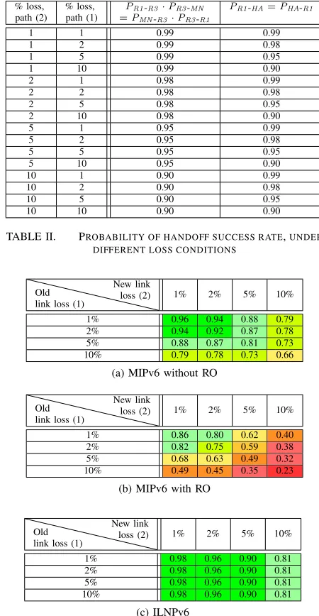
Referring to Figure 6, overall loss is a combination of loss introduced at the old link – between HA and R1, path (1) – as well as the new link – between MN and R1 through R3, path (2). We use packet loss rates of 1%, 2%, 5% and 10% on the paths, and use every combination of these loss rates. Table I presents values of each individual probability used in equation (23) – (25) under each scenario.
C. Results
By placing the values from Table I into equations (23) – (25), Table II presents the handoff success rates for MIPv6, both with and without RO, and for ILNPv6, in each scenario.
As expected, the handoff success rate decreases when the packet loss rate increases. MIPv6 is affected by loss in both the old path and the new path, while only loss on the new path impacts ILNPv6. This is because ILNPv6 uses only the new path for sending the signalling packets (LU and LU-ACK). So, an increase in the packet loss rate of the old path does not affect the handoff success rate for ILNPv6.
[image:6.612.329.554.76.510.2]Under a low loss environment, i.e. 1% and 2% loss, there are only slight differences for the handoff success rate of
TABLE I. INDIVIDUAL PROBABILITIES UNDER DIFFERENT PACKET
LOSS RATES.
% loss, % loss, PR1-R3·PR3-MN PR1-HA=PHA-R1
path (2) path (1) =PMN-R3·PR3-R1
1 1 0.99 0.99
1 2 0.99 0.98
1 5 0.99 0.95
1 10 0.99 0.90
2 1 0.98 0.99
2 2 0.98 0.98
2 5 0.98 0.95
2 10 0.98 0.90
5 1 0.95 0.99
5 2 0.95 0.98
5 5 0.95 0.95
5 10 0.95 0.90
10 1 0.90 0.99
10 2 0.90 0.98
10 5 0.90 0.95
10 10 0.90 0.90
TABLE II. PROBABILITY OF HANDOFF SUCCESS RATE,UNDER
DIFFERENT LOSS CONDITIONS
Old link loss (1)
New link
loss (2) 1% 2% 5% 10%
1% 0.96 0.94 0.88 0.79
2% 0.94 0.92 0.87 0.78
5% 0.88 0.87 0.81 0.73
10% 0.79 0.78 0.73 0.66
(a) MIPv6 without RO
Old link loss (1)
New link
loss (2) 1% 2% 5% 10%
1% 0.86 0.80 0.62 0.40
2% 0.82 0.75 0.59 0.38
5% 0.68 0.63 0.49 0.32
10% 0.49 0.45 0.35 0.23
(b) MIPv6 with RO
Old link loss (1)
New link
loss (2) 1% 2% 5% 10%
1% 0.98 0.96 0.90 0.81
2% 0.98 0.96 0.90 0.81
5% 0.98 0.96 0.90 0.81
10% 0.98 0.96 0.90 0.81
(c) ILNPv6
MIPv6 without RO and ILNPv6. MIPv6 clearly has lower success rate than ILNPv6 when more loss (5% and 10%) is induced. When RO is enabled, MIPv6 is more sensitive to loss because there are a lot more signalling packets involved. The handoff success rate is as low as 75% when the old path and the new path have only 2% packet loss rate. Moreover, the success rate drops to below 50% when more than 5% packet loss rate is induced on both paths.
Overall, ILNPv6 is more robust to the lossy environment. The handoff success rate is more than 90% if the network has less than 5% loss. Even in a very poor network, e.g. 10% loss rate, handoff using ILNPv6 still has more than 80% success rate.
D. Impacts of Signalling Packets Loss
network has higher loss rates. Loss of a handoff signal packet is detected when the MN does not receive the acknowledgement within a specified time (i.e. a standard timeout mechanism), and the signalling packets are retransmitted (which is the case for both MIPv6 and ILNPv6). A retransmission causes the handoff duration to be longer, and thus increases the time that the data plane flow is potentially disrupted.
For MIPv6, the retransmission timeout for BU or BAck is 1.5 seconds [2, Sec. 9.5.5]. This means the handoff delay and the interruption time at the MN would increase by 1.5 seconds if BU or BAck is lost. For ILNPv6, the retransmission timeout of LU and LU-ACK is undefined, but could be any values greater than the round-trip time (RTT) between the MN and the CN. This should be much lower than 1.5 seconds. Moreover, ILNP supports network layersoft handoff(use of both the old path and new path simultaneously) during the time that the MN remains in the overlap area for the 2 networks. So, loss of LU and LU-ACK should not interrupt the data plane for the MN because the MN can still communicate via the old path.
VI. DISCUSSION
Our analyses are based on a single handoff of MNs. Of course, the overhead would increase if MNs handoff more frequently. However, from the results, it can be seen that ILNPv6 should be more scalable and more robust than MIPv6 with RO. Also, this analysis does not include overhead from the DNS update for ILNPv6 because it is not always required (see Section III). However, even when the DNS update is required, the overhead should still remain low since only the number of MNs affects the number of signal packets/bytes – like MIPv6 without RO, the number of CNs is not relevant for DNS updates.
Another important factor that affects overhead and scalabil-ity is caching. For MIPv6 with RO, after the RO process, the CN would have a cache to hold the CoA value of the MN. If the entry expires, the CN would send a Binding Refresh Request message [2, Sec. 9.5.5] to the MN. The MN would perform the return routability procedure as well as BU/BAck handshake with the CN, if it still uses such CoA. This allows subsequent connections to be established directly between the MN and the CN without passing through the HA. However, this also causes extra overhead for the network. With ILNPv6, on the other hand, if the L64 value at the CN expires, a new connection session can be established using DNS, without requiring extra overhead apart from the DNS query.
The simple model we present in this paper could be applied to other solutions, e.g. HIP, LISP and SHIM6 as well as some extensions to MIPv6 including FMIPv6, HMIPv6 and PMIPv6 in order to investigate the scalability and robustness of the protocols, and aid in the solutions design.
VII. CONCLUSION
We provide comparison of the handoff signalling perfor-mance of MIPv6 and ILNPv6 using analytical models. Overall, ILNPv6 handoff signalling is more efficient than MIPv6 with RO in terms of robustness in lossy environments, and scalabil-ity in terms of number of MNs and CNs. For MIPv6 without RO, handoff signalling is about the same level as ILNPv6 in terms of robustness in lossy environments, and better than
ILNPv6 in terms of packet and byte overhead. However, with the well-known problems in handoff performance in the data plane, MIPv6 without RO is unlikely to be used in real life scenarios.
For a high number of MNs and CNs, more overhead (in terms of packets and bytes) is introduced. ILNPv6 generates less than a half the overhead in terms of number of packets and number of bytes compared to MIPv6 with RO. Hence, ILNPv6 is better for use at scale. MIPv6 without RO has a very small overhead.
Lossy networks reduce the handoff success rate of both MIPv6 (with and without RO) and ILNPv6. MIPv6 with RO is the least tolerant to lossy networks, while MIPv6 without RO and ILNPv6 have a relatively similar level of tolerance (ILNPv6 is slightly better).
For the future, we plan to examine the use of ILNP in bandwidth hungry applications like real-time video and large file transfers, as well as investigate in various domains where overhead is a significant issue, for example in IP satellite networks.
REFERENCES
[1] C. Perkins, “IP Mobility Support for IPv4, Revised,” IETF, RFC 5944
(PS), Nov 2010.
[2] C. Perkins, D. Johnson, and J. Arkko, “Mobility Support in IPv6,” IETF,
RFC 6275 (PS), Jul 2011.
[3] R. Atkinson, S. Bhatti, and S. Hailes, “Evolving the Internet
Archi-tecture Through Naming,” Selected Areas in Communications, IEEE
Journal on, vol. 28, no. 8, pp. 1319 –1325, october 2010.
[4] ——, “ILNP: mobility, multi-homing, localised addressing and
security through naming,” Telecommunication Systems, vol. 42,
pp. 273–291, 2009. [Online]. Available: http://dx.doi.org/10.1007/ s11235-009-9186-5
[5] R. Atkinson and S. N. Bhatti, “Identifier-Locator Network Protocol
(ILNP) Architectural Description,” IRTF, RFC 6740 (E), Nov 2012. [Online]. Available: http://tools.ietf.org/html/rfc6740
[6] ——, “Identifier-Locator Network Protocol (ILNP) Engineering
Considerations,” IRTF, RFC 6741 (E), Nov 2012. [Online]. Available: http://tools.ietf.org/html/rfc6741
[7] R. Atkinson, S. N. Bhatti, and S. Rose, “DNS Resource Records for
the Identifier-Locator Network Protocol (ILNP),” IRTF, RFC 6742 (E), Nov 2012. [Online]. Available: http://tools.ietf.org/html/rfc6742
[8] R. Atkinson and S. N. Bhatti, “ICMP Locator Update Message for
the Identifier-Locator Network Protocol for IPv6 (ILNPv6),” IRTF, RFC 6743 (E), Nov 2012. [Online]. Available: http://tools.ietf.org/ html/rfc6743
[9] ——, “IPv6 Nonce Destination Option for the Identifier-Locator
Network Protocol for IPv6 (ILNPv6),” IRTF, RFC 6744 (E), Nov 2012. [Online]. Available: http://tools.ietf.org/html/rfc6744
[10] ——, “Optional Advanced Deployment Scenarios for the
Identifier-Locator Network Protocol (ILNP),” IRTF, RFC 6748 (E), Nov 2012. [Online]. Available: http://tools.ietf.org/html/rfc6748
[11] Z. Zhu, R. Wakikawa, and L. Zhang, “A Survey of Mobility Support
in the Internet,” IETF, RFC 6301 (I), july 2011.
[12] H. Soliman, C. Castelluccia, K. ElMalki, and L. Bellier, “Hierarchical
Mobile IPv6 (HMIPv6) Mobility Management,” IETF, RFC 5380 (PS), Oct 2008.
[13] R. Koodli, “Mobile IPv6 Fast Handovers,” IETF, RFC 5568 (PS), July
2009.
[14] E. Ivov and T. Noel, “An experimental performance evaluation of the
IETF FMIPv6 protocol over IEEE 802.11 WLANs,” in Proc IEEE
WCNC 2006, vol. 1, April 2006, pp. 568–574.
[15] S. Gundavelli, K. Leung, V. Devarapalli, K. Chowdhury, and B. Patil,
[16] H. Chan, D. Liu, P. Seite, H. Yokota, and J. Korhonen, “Requirements for Distributed Mobility Management,” IETF, RFC 7333 (I), August 2014.
[17] D. Liu, J. Zuniga, P. Seite, H. Chan, and C. Bernardos, “Distributed
Mobility Management: Current Practices and Gap Analysis,” IETF, RFC 7429 (I), January 2015.
[18] D. Farinacci, V. Fuller, D. Meyer, and D. Lewis, “The Locator/ID
Separation Protocol (LISP),” IETF, RFC 6830 (E), Jan 2013.
[19] A. Rodriguez Natal, L. Jakab, M. Portoles, V. Ermagan, P. Natarajan,
F. Maino, D. Meyer, and A. Cabellos Aparicio, “LISP-MN: Mobile
Net-working Through LISP,”Wireless Personal Communications, vol. 70,
no. 1, pp. 253–266, 2013.
[20] A. Galvani, A. Rodriguez-Natal, A. Cabellos-Aparicio, and F. Risso,
“LISP-ROAM: Network-based Host Mobility with LISP,” inMobiArch
2014, 2014, pp. 19–24.
[21] E. Nordmark and M. Bagnulo, “Shim6: Level 3 Multihoming Shim
Protocol for IPv6,” IETF, RFC 5533 (PS), Jun 2009.
[22] A. Dhraief and N. Montavont, “Toward Mobility and Multihoming
Unification - The SHIM6 Protocol: A Case Study,” inIEEE WCNC
2008 - Wireless Communications and Networking Conf., March 2008, pp. 2840–2845.
[23] R. Moskowitz, P. Nikander, P. Jokela, and T. Henderson, “Host Identity
Protocol,” IETF, RFC 5201 (E), Apr 2008.
[24] P. Nikander, T. Henderson, C. Vogt, and J. Arkko, “End-Host Mobility
and Multihoming with the Host Identity Protocol,” IETF, RFC 5206 (E), Apr 2008.
[25] R. Moskowitz, T. Heer, P. Jokela, and T. Henderson, “Host Identity
Protocol Version 2 (HIPv2),” IETF, RFC 7401 (PS), April 2015.
[26] C. Makaya and S. Pierre, “An Analytical Framework for Performance
Evaluation of IPv6-Based mobility Management Protocols,” Wireless
Communications, IEEE Transactions on, vol. 7, no. 3, pp. 972–983, March 2008.
[27] S. Zeadally and F. Siddiqui, “An Empirical Analysis of Handoff
Performance for SIP, Mobile IP, and SCTP Protocols,”Wireless Personal
Communications, vol. 43, no. 2, pp. 589–603, Oct. 2007.
[28] J. Rosenberg, H. Schulzrinne, G. Camarillo, A. Johnston, J. Peterson,
R. Sparks, M. Handley, and E. Schooler, “SIP: Session Initiation Protocol,” IETF, RFC 3261 (PS), June 2002.
[29] R. Stewart, “Stream Control Transmission Protocol,” IETF, RFC 4960
(PS), Sep 2007.
[30] D. Rehunathan and S. Bhatti, “A comparative assessment of routing for
mobile networks,” inWireless and Mobile Computing, Networking and
Communications (WiMob), 2010 IEEE 6th International Conference on, Oct 2010, pp. 434–441.
[31] V. Devarapalli, R. Wakikawa, A. Petrescu, and P. Thubert, “Network
Mobility (NEMO) Basic Support Protocol,” IETF, RFC 3963 (PS), Jan 2005.
[32] R. Atkinson, S. Bhatti, and S. Hailes, “A Proposal for Unifying Mobility
with Multi-Homing, NAT, and Security,” inMobiWAC’07 – 5th ACM
Intl. Wkshp. on Mobility Mgmt. and W’less Access, Oct 2007.
[33] R. Atkinson, S. N. Bhatti, and S. Hailes, “Mobility as an Integrated
Ser-vice Through the Use of Naming,” inMobiArch 2007 - 2nd ACM/IEEE
Intl. Workshop on Mobility in the Evolving Internet Architecture, Aug 2007, pp. 1:1–1:6.
[34] D. Phoomikiattisak and S. N. Bhatti, “Network Layer Soft Handoff
for IP Mobility,” inProc. PM2WH2N 2013 - 8th ACM Wrkshp. Perf.
Monitoring and Measurement of Heterogeneous Wireless and Wired Networks, 2013, pp. 13–20.
[35] ——, “IP-layer Soft Handoff Implementation in ILNP,” in MobiArch
2014, 2014, pp. 1–6. [Online]. Available: http://doi.acm.org/10.1145/
2645892.2645895
[36] ——, “Mobility as a First Class Function,” in WiMob 2015 - IEEE
Intl. Conf. Wireless and Mobile Computing, Networking and Comms., October 2015, pp. 858–867.
[37] S. Baset and H. Schulzrinne, “An Analysis of the Skype
Peer-to-Peer Internet Telephony Protocol,” in INFOCOM 2006. 25th IEEE