A Modelling Language to Support the Evolution of
Multi-Tenant Cloud Data Architectures
Assylbek Jumagaliyev, Yehia Elkhatib
∗School of Computing and Communications, Lancaster University, United Kingdom {i.lastname}@lancaster.ac.uk,∗ORCID0000-0003-4639-436X
Abstract—Multi-tenant data architectures enable efficient re-source utilization in cloud applications, but are currently being implemented in industry and research using manual coding techniques that tend to be time consuming and error prone. We propose a novel domain-specific modeling language,CadaML, to automatically manage the development and evolution of cloud data architectures that (a) adopt multi-tenancy and/or (b) comprise of a combination of different storage solutions such as relational and non-relational databases, and blob storage.
CadaML provides concepts and notations to support abstract modelling of a multi-tenant data architecture, and also provides tools to validate the data architecture and automatically produce application code. We rigorously evaluateCadaMLthrough a user experiment where developers of various capabilities are asked to re-architect the data layer of an industrial business process analysis application. We observe that CadaML users required 3.5x less development time than manual coders. In addition to improved productivity, CadaML users highlighted other benefits gained in terms of reliability of generated code and usability.
Index Terms—Domain-Specific modeling, Model-Driven Engi-neering, Cloud Computing, Multi-tenancy, Software Evolution, Code Generation
I. INTRODUCTION
Multi-tenancy is an architectural pattern where a single instance of an application serves multiple tenants [1]. In this context, a tenant is a group of users that belongs to an organization who has access with specific privileges [2]. For example, a multi-shop e-commerce platform would store data from different shops (i.e., tenants) on the same data store. Multi-tenancy is commonly adopted in cloud environments as it enables efficient resource utilization, and leads to lower operation and maintenance costs through consolidation [3].
Introducing multi-tenancy affects development and evolu-tion overheads at all layers of the applicaevolu-tion structure, and the data layer is no exception. Multi-tenancy at the data layer requires a data architecture to ensure isolation of tenant data and requests, on top of the ability to scale. The data architecture typically also needs to be extensible to support tenant-specific customizations.
A further complication in the case of multi-tenant cloud applications is the tendency to store data in different storage types [4],i.e.,relational and non-relational databases, and blob storage. These are conceptually diverse, with each having its own partitioning and extensibility approaches to support multi-tenancy. Thus, building a data architecture that maximizes
This work was partially supported by theAdaptive Brokerage for the Cloud (ABC) project, UK EPSRC grant reference EP/R010889/1.
resource sharing with the optimal degree of isolation requires developers to address multi-tenancy challenges and to find a balance between several architectural trade-offs.
Domain-Specific Languages (DSLs) have been long pro-posed to address multi-tenancy concerns, specifically to gener-ate and/or maintain cloud implementations. DSLs are concise, simple and expressive languages that aim to address prob-lems of a specific domain through high level and abstract notions [5]. There have been some successful approaches to describe deployment configurations, provisioning and man-agement of cloud services (e.g., [6]–[9]), but multi-tenancy at the data layer has not been appropriately addressed. For example, CloudDSL [8] allows the specification of deployment information for a data layer on different cloud storages, but the actual data architecture and multi-tenancy management patterns are not supported. Other model-based techniques [10], [11] capture multi-tenancy patterns in the data layer as a part of the application structure, but offer no support for implementation of the expressed multi-tenancy model.
In this paper, we present CadaML: a modeling language for the design and implementation of cloud application data architectures.CadaMLis specifically designed to support multi-tenant data architectures on different cloud storage types. It provides graphical and automated support to build a data architecture as a model, validate the model, and generate the appropriate source code including various ways of managing multi-tenancy. While a preliminary design of CadaML was presented in [12], here we refine it and empirically evaluate it using experimentation with developers. We show howCadaML
allows general developers to easily re-architect the data layer of an industrial business process analyzing web application to support multi-tenancy. Compared to the traditional manual approach, using CadaML significantly increases productivity: developers are able to complete 3.5x or more the amount of tasks in the same amount of time. It also noticeably improves reliability of data layer implementation. As a result,CadaML
enables developers to focus on the application business logic instead of the minutiae of multi-tenant data layer management.
Our contributions in this paper are:
1) CadaML, a novel domain-specific modeling language for building multi-tenant polyglot data architectures of cloud applications. CadaML is graphical and does not require any syntax to be learned.
model-to-code transformation.
3) The design and implementation of a code generation engine that uses a validated model to synthesize a data layer implementation with multi-tenancy management logic that corresponds to the specific data storage types and policies selected by the developer.
4) An empirical evaluation of CadaML through an experi-mental case study of an industrial application. We specif-ically observe the productivity of developers of vary-ing abilities, the reliability of the generated code, and
CadaML’s usability.
II. PROBLEMSPACE
When developing a multi-tenant application, a high priority is to design a configurable and scalable data architecture that maximizes resource sharing across tenants, and one that is also efficient and cost-effective to implement and maintain [13]. However, cloud applications usually have a variety of data storage requirements and are often served best by a combina-tion of storage opcombina-tions [4], [14], [15]. These options differ in storing and organizing data, each having its own partitioning and extensibility approaches to support multi-tenancy.
A. Data store types
We focus on the Platform-as-a-Service (PaaS) provisioning level of cloud computing as the one most popular with developers [16], [17]. We describe PaaS storage, and illustrate the differences in storing and organizing data with each type.
• Relational databases are appropriate for structured data with a well-defined schema. Data is organized in tables of rows and columns, with aprimary keyidentifying each row. Relationships are strongly defined in the data model.
• Non-relational databases (also called NoSQL) mainly support key-value stores, and are suitable for flexible data schemas. Apartition keydetermines the partition in which data will be stored, and a row key identifies data within each partition.
• Blob/Object storage is ideal for completely unstructured data such as documents, media files, or binary data. Data is stored in buckets as a blob, where a key uniquely identifies each blob (i.e.,object or item) within abucket.
B. Data architecture partitioning schemes
A partitioning scheme is crucial to ensure isolation of tenant data, and scalability of the solution when sharing application code and data across all tenants. Each cloud storage type has its own partitioning techniques. In this subsection, we summarize these techniques after analyzing academic and industrial literature, as well as cloud provider guidance.
In general, relational databases can be partitioned using: (i) Separate databases: each tenant is served by a dedicated database; (ii) Shared database, separate tables: all tenants are hosted by a single database with separate tables per tenant (with a tenant identifier in the table name, or a separate schema can be used for each tenant); or (iii) Shared database, shared
tables: all tenants share tables in a single database, with a tenant identifier is used to associate their records in each table. Non-relational databases can be partitioned in one of two ways: separate tables or shared tables. In the former, each tenant’s data is stored in tenant-specific tables with a tenant identifier as part of table names. In the latter, all tenant data is stored in shared tables and a tenant identifier is included in partition keys to associate rows with a tenant.
Separate and shared buckets are the main partitioning techniques for blob storage. In separate buckets, all blobs belonging to a specific tenant are stored in a single bucket where a tenant identifier is included in the bucket name. In contrast, shared buckets stores all tenant data in the same buckets, but includes tenant identifiers in the blob names.
Given these varying partitioning schemes, manually imple-menting a multi-tenant data architecture can be highly time-consuming and error-prone especially for architectures utiliz-ing more than one storage type. Recent research has aimed to generate multi-tenant cloud applications from high-level models in order to hide cloud-specific implementation details, cf.[6], [7], [10], [11], [18]. However, existing approaches tend to focus less on managing multi-tenancy in the data layer, and instead focus on other aspects such as enabling configurable application functionality, capturing different functional and quality-of-service tenant requirements, etc.
C. Research objectives
To address the limitations of previous work, we present
CadaMLto design a multi-tenant data architecture, and generate source code that is suitable for different cloud storage types that are required. Specifically, through this work we aim to achieve the following objectives:
RO1: Provide a means for developers to describe a multi-tenant cloud data architecture at an abstract level.
RO2: Reduce the development effort during the implemen-tation of a multi-tenant cloud data architecture.
RO3: Improve reliability of the application code (specifically at the data layer).
RO4: Offer developers with a reasonable level of usability.
III. CadaML: CONCEPTS ANDIMPLEMENTATION
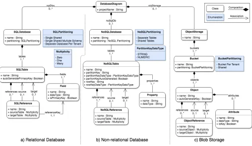
Figure 1. The meta-model ofCadaML
to go through all these steps and modify the existing code. This process is usually time-consuming and error prone.
To ease the development process of multi-tenant data ar-chitectures, we propose CadaML that allows developers to describe a data architecture in an abstract level by hiding the implementation details of different cloud storage types (i.e.,polyglot data stores). A data layer implementation work-flow using CadaML involves the four steps: (i) First, as in the manual approach, data layer requirements are captured; (ii) The requirements are analyzed and a data architecture model is designed using the graphical editor of CadaML; (iii) The model is validated for constraints and validation rules imposed by CadaML; and (iv) The data access layer source code is produced from the model. In this scenario, changes in the requirements can be directly reflected in the model, thus, code is generated from the model.
Compared to the manual approach, CadaMLautomates data access layer implementation by generating source code from the data architecture model. In addition, the validation tool eliminates the testing phase through handling errors at the model level before generating any artefact from the model.
A. The meta-model
Modeling languages are defined in a meta-model that de-scribes language elements and relationships among them [5]. The concepts and notations of CadaML should correspond to terminology that cloud data layer architects and developers
are familiar with. Thus, the meta-model has been created by thoroughly analyzing common storage type characteristics of major providers (namely, Alibaba Cloud, Amazon Web Ser-vices (AWS), Google Cloud Platform, and Microsoft Azure), features of existing modeling languages that support cloud application development (e.g.,[10], [11]), and peculiarities of cloud data storage partitioning techniques that were described in academic and industrial literature (e.g., [10], [11], [13], [19]).
SQL-Partition of a relation database is classified according to partitioning schemes that were described in §II-B. A SQL databaseis composed of tables and their relationships that are represented by SQL table andSQL reference, respectively. A SQL tableconsists offields, and eachfieldhasname,data type andisPrimaryKeyparameters where the last parameter defines whether the field is a primary key. In addition, autoGen-eratePrimaryKey parameter allows to automatically generate primary key values of a table by the application. The source and target parameters of SQL reference refer to tables in a relationship, and reference keyindicates to a foreign key in a target table. Where multiplicity between tables are expressed by source tableandtarget tableparameters.
Object Storage is associated with Blob storage type. In blob storage, data is stored in buckets. A developer can specify partition of a bucket to one of the described in §II-B partitioning schemes. Object represents a blob that is persisted in a bucket. An objectis a set of attributes, where each attributehasname,data typeandisKey parameters. The isKey parameter determines whether anattribute is a key that will be associated with the object. A key for a blob can be automatically generated by settingautoGenerateKeyparameter of an object to true. An object can be in relationships with other objects which are expressed by object reference. The source andtarget parameters refer to blobs in a relationship, while multiplicity between blobs are expressed by source object andtarget objectparameters.
B. Multi-tenancy management
Multi-tenancy is supported by capturing data segmenta-tion patterns of different data storage solusegmenta-tions in the meta-model. Hence, developers can specify a desired partitioning scheme for each storage type while modeling a data arch-itecture. Partitioning schemes are defined at bucket level for blob storage, and database instance level for relational and non-relational databases. Based on defined schemes, CadaML
produces corresponding implementation of the data access layer. For example, in a shared bucket tenant isolation is implemented by appending the tenant identifier to the blob key when uploading and retrieving blobs. Another example, a tenant-specific schema name is specified when establishing a connection to a shared relational database with separate tables partitioning scheme.
The described meta-model offers benefits above existing work, which mostly capture cloud services for defining pro-visioning and deployment configurations of application com-ponents. A few meta-models includes multi-tenancy patterns for relational databases but do not comprise concepts to model a cloud data architecture. In contrast, CadaML allows to explicitly model a data architecture for different cloud storage types with partitioning schemes, in line with current best practices in this space, e.g.,[20].
C. Implementation
[image:4.612.314.562.48.228.2]CadaMLhas been implemented as a plugin for Eclipse IDE. We decided to implement CadaML as a graphical modeling
Figure 2. The concrete syntax ofCadaMLimplemented as a graphical editor
language because of the following benefits. First, visual repre-sentation of a data architecture makes designing database ele-ments and relationships among them more convenient. Second, it is easier to find and correct errors in a graphical model [21]. Finally, visualization of a model allows non-developers to get an overview of a data architecture and intuitively develop an understanding of the data layer design.
A screenshot of the CadaML graphical editor is shown in Figure 2, and it consists of three parts: 1 a canvas represents DatabaseDiagram from the meta-model in which a modeler creates model elements, and the relationships that define links between model elements; 2 the Palette comprises tools associated with the model elements specified in the meta-model; and 3 the Properties tab that shows properties of each selected model element in the canvas.
The meta-model was created using the Emfatic notation [22] and annotated using EuGENia [23] in order to be transformed into a concrete Graphical Modeling Framework editor in the Eclipse IDE. Our customizations amounted to 4,684 lines of code written to implement CadaML: 203 for the implementa-tion of the meta-model, 106 for adjusting the graphical editor, 315 for validation, and 4,060 for code generation.
D. Validation rules and constraints
A key advantage of CadaMLis that the model is validated against the meta-model semantics before generating derivative artefacts. Constraints and validation rules are enforced at the level of the model that can handle many kinds of errors. For example, names of storage type elements (e.g., tables, fields in a table, buckets, objects within a bucket) in a data architecture must be unique and valid identifiers. As another example, non-relational tables must have both partition and row keys, while relational tables must have primary keys. In
E. Code generation
The main objectives of CadaMLare to increase both devel-oper productivity and code reliability by (semi-)automating data architecture implementation. To achieve these goals,
[image:5.612.49.295.161.342.2]CadaML includes a code generator that automatically and rapidly transforms a model created by a developer to exe-cutable Java code for AWS.
Figure 3. The code generation process
The code generator (Figure3) is written in Epsilon Genera-tion Language [23], and it produces 1) data models, 2) storage context classes, 3) Java interfaces, and 4) cloud specific classes for each storage type. All code that is specific to a storage type is located in different packages. In addition, the generated code decouples the data access logic from other layers of the application. This separation, crucially, provides ease of code maintenance, and allows to independently scale the data layer. Blobs, relational and non-relational tables are each trans-formed into a data model, a Java class with appropriate getters and setters. For relational and non-relational tables, data mod-els are annotated using Java Persistence API and DynamoDB Java Annotations, respectively. The annotations are used to map object fields to actual attribute names in database tables. A storage context class contains storage related fields, such as provider name, storage credentials, region, and replication to initialize a storage connection. In the meantime, a Java interface contains generic method signatures that are further implemented by provider-specific classes.
The blob storage interface contains methods to initialize storage, create a bucket, upload a blob, retrieve a single blob, retrieve a list of blobs and delete a blob. Meanwhile, the relational database interface includes create, update, read and delete (CRUD) methods. Finally, the non-relational database interface has methods to create a table, save an item in a table, retrieve an item, and delete an item from a table. It is worth noting that cloud provider specific classes implement methods in a generic way that work on different data models.
IV. INDUSTRIALUSECASE
To investigate the practical feasibility and to assess the utility of applying CadaML, we conducted an experiment to re-engineer the single-tenant data layer of a web application from our industrial partner to adopt multi-tenancy.
A. Use case background
The chosen use case is a business process analyzing ap-plication from our industrial partner, a major telecommuni-cation provider operating in 150+ countries. The applitelecommuni-cation is distributed to many subsidiaries (hereafter, tenants) of a holding company, and the purpose of the application is to ensure compliance of business processes of each subsidiary with the policies imposed by the holding company. The data architecture consists of 18 entities with their interrelations, which are designed for relational databases. For our experi-ment, we use the core subset of these entities. We also spread the application’s data into different cloud storage types to make the solution scalable and to reduce the costs for data storage.
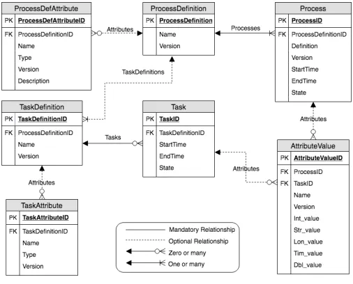
Figure 4. ER diagram of the business process analyzing application
An entity-relationship (ER) diagram of the experimental data architecture is presented in Figure4. Theprocess defini-tionentity defines a business process, and it comprisesprocess andtask definition. The processentity describes a job, order, or process execution, such as service fulfillment or fault repair process, while task definition defines a description for atask in a business process. The remaining entities, namely,process attribute, task attribute, and attribute value, hold additional attributes to provide extensibility of the data architecture.
[image:5.612.311.564.288.492.2]its regulations. The holding company wants to change this allocation. It aims to evolve the application into a multi-tenant cloud service. Hence, tenants subscribe to the application, and the company can perform analysis anytime without requiring tenants to send their reports. Moreover, sharing an application and a database instances by all tenants will reduce the deploy-ment and maintenance effort which leads to lower costs.
B. Evolving the data architecture
[image:6.612.312.566.50.171.2]During the evolution process, the data architecture of the use case is re-designed to use a combination of different cloud storage solutions. This, in turn, provides scalability, customizability and extensibility of the data layer, and reduces the costs for data storage. Figure 5 shows, at a high level, which data is stored in the different types of storage.
Figure 5. Data storage in the business process application
The application collects most of the tenant information with configuration data during on-boarding process, and stores them as a single object in a public bucket named‘tenants’. Atenant and itsconfigurationare modeled as separate entities to enable customization and management of each entity independently. These entities will be deployed to Amazon S3.
In the meantime, the application stores process definitions, processes,task definitions and tasksentities in separate non-relational tables in Amazon DynamoDB. Storing these enti-ties in non-relational tables simplifies the implementation of customizability and extensibility of the application. To extend these tables in a relational database, additional tables are used to hold custom attributes. Fortunately, non-relational tables allow to use multiple schemes in the same table, thus, each tenant can have its own custom attributes.
Nevertheless, non-relational databases support limited oper-ations which restricts execution of complex queries. Therefore, for tenants who need complex analysis and management of their own custom reporting requirement, the application will provision a new relational database instance of Amazon RDS during the on-boarding process. For tenants with such requirements, the provisioning process will create necessary tables in the database. Ideally, the actual database scheme should be remained unchanged. For the experiment, the same set of entities that are used for non-relational databases but with different organizational structure are constructed.
C. Modeling in CadaML
CadaML is used to model the data architecture of the use case. First of all, a database diagram needs to be created with instances of the corresponding cloud storage types (i.e., Object Storage,NoSQL DatabaseandSQL Database).
Figure 6. Blob storage data architecture modeled inCadaML
As shown in Figure 6, a single bucket is created in the object storage. The ‘Shared’partitioning scheme is specified for thebucketsince thebucketis used as a central storage for tenant-specific configuration data, and it is shared across all tenants. Within the bucket,Tenant andConfigurationentities are modeled as objects with attributes, and the relationship between theseobjectsare defined by the object reference.
[image:6.612.49.302.239.302.2]The Tenant object has ‘Name’ and ‘SubscriptionKind’ at-tributes where the first attribute is set as thekey that will be associated with an instance of theobjectwhen storing it in the bucket. Meanwhile,‘Configuration’object holds configuration information that is used to provision a new relational database instance, and it is bound to theTenant object.
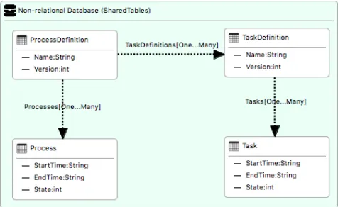
Figure 7. Non-relational data architecture modeled inCadaML
[image:6.612.317.555.388.534.2]The partition key for the ProcessandTaskDefinitiontables contain the row key from theProcessDefinitiontable, which is the process definition identifier. This enables the application to insert all processes and task definitions for a process definition in a single transaction, and to retrieve them from a single partition. In the meantime, the Process and TaskDefinition tables hold the process identifier and task definition identifier, respectively, in their row keys.
[image:7.612.49.297.216.387.2]Similarly, the identifying row key of theTaskDefinitiontable is set as the partition key for the Task table, and the task identifier is included in the row key. Other elements of entities are added asproperties, and the relationships between entities are captured by NoSQL reference.
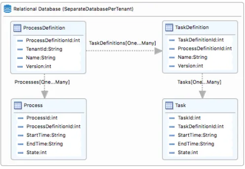
Figure 8. Relational data architecture modeled inCadaML
As depicted in Figure8, aSQL databaseinstance is created with the‘Separate Database Per Tenant’partitioning scheme, as the application will provide an instance of SQL database for tenants who require additional reporting capabilities. Re-lational entities are created as SQL tables with their fields. For primary key fields, isPrimaryKey property is set to true. The relationships are specified using SQL reference, where a foreign key serves as a link between entities.
When the data architecture is designed, the developer can check the model for errors and validate it. If there is no violation of constraints and validation rules, the model is transformed to Java code for AWS. This one-time process takes≈1.9seconds on a machine with an Intel i5 1.30GHz.
V. EVALUATION
We first detail our experimental setup (§V-A), then present and comment on the results (§V-B – §V-D).
A. Experiment design
Strategy: Our evaluation strategy is to exploit the use case to assess developer productivity in terms of time required to develop the data layer for AWS and completion rate of the experiment tasks, theusability of CadaML, and generated code reliability. We compareCadaMLagainst manual code re-factoring where developers implement the data layer of the given use case. The controlled experiment design with the
Table I
SELF-REPORTED EXPERTISE IN PROGRAMMING WITHJAVA.
Low (1-2)
Medium (3-5)
High (6-7) Total
Manual 1 5 5 11
CadaML 1 4 7 12
Sum 2 9 12 23
Table II
SELF-REPORTED EXPERTISE IN CLOUD DEVELOPMENT AND MODELING.
Cloud Appl’s
Cloud Data Layer
Modeling Tools
None of the above Total
Manual 4 3 3 1 11
CadaML 3 2 5 2 12
Sum 7 5 8 3 23
task analysis technique is used to observe how participants interact with CadaML. Such analysis helps in understanding the difficulties participants face in using the modeling language and improvements that might be needed.
Procedure: The experiment procedure lasts for a maximum of an hour per participant (plus assistance time, see below). First, the participant fills a questionnaire about their experience in programming languages, cloud application/data layer devel-opment and modeling tools. Then, the participant is assigned to implement the data architecture using either CadaML or through manual coding in alternating order in order to avoid interaction effects and to ensure equal number of participants for both approaches. All participants used the same high-end development PC. Finally, those who used CadaML are interviewed at the end of the experiment to discuss reliability of the code, usability of the modeling language, and how
CadaMLaffected their productivity. They are asked to respond to a simple questionnaire using a 5-point Likert scale, then optionally answer open-ended questions to solicit feedback on things to improve.
Task: The experiment task is divided into 3 independent sections for each of the storage types, which can be attempted in any order. Each section consists of a list of implementation tasks that are then used as a checkpoint system to gauge the level of completion for each participant. There are 20 tasks in the relational databases section, 18 in non-relational databases, and 8 in blob storage.
Assistance: Before the experiment commences, the Amazon Web Services API documentation and annotated code samples are given to manual implementers, and a brief quickstart guide (2-3 minutes) toCadaMLusers. During the experiment, additional guidance is provided for any participant who has trouble interacting with either Amazon APIs orCadaML.
Recruitment:Participants were recruited from local Computer Science researchers and graduate students, as well as startup developers. An incentive for participation was offered in the form of an online shopping voucher (value of £10 ≈
Table III
TIME SPENT(IN H:MIN:S)AND COMPLETION RATE(CR)BY PARTICIPANTS FOR EACH STORAGE TYPE THROUGH MANUAL IMPLEMENTATION
Blob Storage NoSQL SQL Overall
Time CR Time CR Time CR Time
P1 31:39 50.0% 29:07 25.0% - 0.0% 1:00:46
P2 25:48 62.5% 35:02 40.0% - 0.0% 1:00:50
P3 36:26 62.5% 23:41 20.0% - 0.0% 1:00:07
P4 39:12 87.5% 21:02 20.0% - 0.0% 1:00:14
P5 - 0.0% 25:22 25.0% 34:44 30.0% 1:00:06
P6 - 0.0% 1:00:09 52.0% - 0.0% 1:00:09
P7 - 0.0% 1:00:23 60.0% - 0.0% 1:00:23
P8 38:54 100.0% 21:06 20.0% - 0.0% 1:00:00
P9 41:23 62.5% 18:38 20.0% - 0.0% 1:00:01
P10 36:24 100.0% 23:36 25.0% - 0.0% 1:00:00
P11 24:48 75.0% 20:55 25.0% - 0.0% 45:23
Median 36:25 62.5% 23:41 25.0% 34:34 30.0% 1:00:07
Table IV
TIME SPENT(IN H:MIN:S)AND COMPLETION RATE(CR)BY PARTICIPANTS FOR EACH STORAGE TYPE USINGCadaML
Blob Storage NoSQL SQL Overall
Time CR Time CR Time CR Time
P12 15:28 100.0% 14:55 100.0% 20:05 100.0% 50:28 P13 13:40 100.0% 11:48 100.0% 15:57 100.0% 41:25 P14 13:26 100.0% 08:24 100.0% 11:03 100.0% 32:53 P15 08:41 100.0% 06:07 100.0% 10:19 100.0% 25:07 P16 13:08 100.0% 12:11 100.0% 16:36 100.0% 41:55 P17 16:46 100.0% 15:54 100.0% 19:40 100.0% 52:20 P18 16:09 100.0% 19:07 100.0% 12:41 100.0% 47:57 P19 10:18 100.0% 11:32 100.0% 09:08 100.0% 30:58 P20 16:18 100.0% 18:06 100.0% 17:12 100.0% 51:36 P21 11:27 100.0% 11:36 100.0% 12:43 100.0% 35:46 P22 22:17 100.0% 19:53 100.0% 16:23 100.0% 58:33 P23 09:54 100.0% 12:16 100.0% 08:07 100.0% 30:17 Median 13:33 100.0% 12:14 100.0% 14:20 100.0% 41:40
CadaML. Furthermore, 7 developers had some cloud applica-tion implementaapplica-tion experience and only 5 among them had data layer implementation experience – see Table II. Nearly the same number of developers (8) have used modeling tools. Both tables emphasize that developers are as fairly allocated for both approaches as possible, without taking specific skills into consideration.
B. Productivity results
The productivity of participants is evaluated by calculating the implementation time, and completion rate of tasks through testing and debugging written/generated code.
Table III shows the time taken to manually develop the data architecture, as well as the associated completion rate of implementation tasks per storage type. Participants spent an average of 32 minutes per storage type, with a median completion rate of 63% for blob storage and 25% for non-relational database.
More importantly, within the one hour of time given for the experiment, none of the participants could fully accomplish all tasks using manual methods. Two participants (P8 and P10) showed 100% completion rate for blob storage, with the best completion rate for non-relational data architecture being 60%. Meanwhile, only one participant (P5) attempted to manually implement the data layer for relational database, completing only 30% of the given tasks. This clearly demonstrates the
complexity of successfully completing the required tasks using manual methods in under an hour.
In stark contrast, using CadaML significantly improves the development time and completion rates as demonstrated in Table IV. Interestingly, participants spent around 14 minutes on average to model the data architecture of each storage type. The minimum times required for blob storage, non-relational and non-relational databases were about 9, 6, and 8 minutes, respectively. Meanwhile, the maximum times were 22 minutes for blob storage, and 20 minutes for non-relational and relational databases. Moreover, all participants fully completed the tasks within the hour, and the generated code passed all test cases (more details in the following subsection).
Figure 9. The distribution of time taken by participants to implement the data layer using 3 different datastore types. UsingCadaMLsignificantly reduces development time. Only one participant attempted to accomplish any progress on SQL using manual implementation, hence the very narrow box on the right.
C. Reliability results
We also evaluated the reliability of the written/generated code on a module level using the JUnit 5 testing framework. Noticeably more errors were encountered in the application code by participants who manually implemented the data access layer. Specifically, errors were discovered in the code of 9 (out of 11) participants. On the contrary, CadaML users fared better: only 5 (out of 12) participants made errors in the data architecture model, most of which were captured.
During the manual implementation experiment, the most common errors were incorrect implementation of: (i) object serialization and de-serialization to upload and retrieve a blob; (ii) non-relational table creation; and (iii) storing referenced entities in a non-relational database. The reasons for these errors seem to stem from some participants perceiving the provided code samples as prescriptive rather than illustrative. For example, in the Amazon tutorial, an example is given of uploading a file as a blob. Some participants simply ignored this fact, and blindly followed the tutorial when instead they needed to upload as a Java object (not a blob), which obviously caused errors. Another reason is the time constraint. Some participants may have felt the need to to fully accomplish the experiment tasks in the allocated time of an hour without ensuring the validity of their code.
Conversely, there were no fundamental errors in the code generated by CadaML. Moreover, most errors were captured and fixed by the validation tool – see §III-D. Examples of such errors include: (i) missing primary keys for relational tables; (ii) incorrect multiplicity specification for a relationship be-tween non-relational tables; and (iii) creation of relationships between the wrong tables. The participants who encountered such errors admitted that the reason for errors was lack of attention while following the experiment tasks. This might suggest too much reliance on CadaML, although it is difficult to tell if this is indicative without conducting a wider study.
D. Exit interview results
After the experiment, participants who used CadaML were interviewed about their experience in exploiting the modeling
language. They were asked a series of 9 questions, to which they respond using a 5-point Likert scale (‘Strongly disagree’, ‘Disagree’, ‘Neutral’, ‘Agree’, and ‘Strongly agree’). The first three questions aim to find out how CadaML affects productivity. The next three questions relate to reliability of the generated code, while the remaining ones focus on usability.
[image:9.612.316.557.239.304.2]Productivity (Figure 10): All participants agreed that less time than expected was required to come up with source code and thatCadaMLmade the implementation process easier through visualization of the data architecture. Half of the participants claimed that no extra manual coding was required to accomplish the experiment. The other half, however, stated that some extra manual coding may be needed depending on application requirements.
Figure 10. Participant feedback on productivity: all agreed that CadaML helps reduce implementation time and difficulty, but not all agreed that it was sufficient on its own.
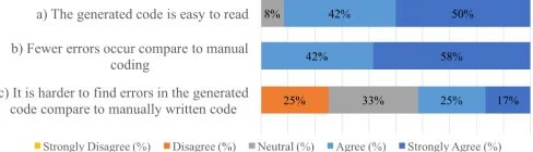
Reliability (Figure 11): The majority of participants (92%) found the generated code to be readable, while only one participant (8%) neither agreed nor disagreed. All participants stated that fewer errors occurred in the code withCadaML in comparison with manual implementation. However, 42% of participants found it harder to locate errors in the generated code compared to the manually-written alternative.
Figure 11. Participant feedback on reliability: generated code is of high readability and low frequency of errors; but with mixed perceptions about the ability of finding errors in the generated code.
Usability (Figure 12):Most participants found CadaMLeasy to use (83%), flexible enough (67%), and with intuitive con-cepts and notations (92%). Nonetheless, a few participants struggled in using CadaML and stated that the modeling language restricts their freedom as a programmer (8% agreed and 25% neutral).
VI. DISCUSSION
[image:9.612.314.558.447.517.2]Figure 12. Participant feedback on usability:CadaMLis generally perceived to be intuitive and easy to use without restricting the developers’ freedom.
A. Reflection on the research objectives
All participants emphasized that the graphical editor makes modeling a data architecture more convenient. They also highlighted that the visual representation eases understanding of the model, and saves effort when applying changes in the model. The majority of the participants were satisfied with the concepts and notations provided by the language. Hence, we achieved objectives RO1 and RO2by providing a way to design a multi-tenant data architecture in an abstract level and reducing the development effort through modeling. The interview results also support our last objective (RO4) where we aimed to offer a reasonable level of usability.
Less errors occurred in the application code due to the validation capability of CadaML. In addition, good readability of the generated code was noted by the participants. On the other hand, finding assumed errors in the application code was not straightforward for some participants because of the number of generated Java classes. This problem can be solved by incrementally testing and debugging the application code. Nonetheless, we can say that RO3is also achieved asCadaML
improved reliability of the application code by reducing the number of errors and producing well structured code.
B. Limitations and future work
For the evaluation, developers of varying familiarity with Java and cloud data layer architectures were recruited. This helped identify baseline improvement across a wide developer-base. However, a more in-depth study with experienced cloud data layer developers would provide further insights.
Changes in the generated code are currently not reflected in the model. As a result, synchronization issues that could emerge between model and code. Also, changes in the code will be overwritten when a developer re-generates it from the model. This is something we plan to mitigate in the future.
We also intend to address concerns about reliability of error localization, and restriction of developer freedom that were collected through the exit interviews. Finally, we plan to further evaluate the generalizability of the modeling language by expandingCadaMLto support different data storage types of multiple cloud service providers, supporting the development of multi-tenant applications that span multiple clouds.
VII. RELATEDWORK
An XML-based modeling language [24] is provided by Topology and Orchestration Specification for Cloud Applica-tions (TOSCA) to define application components and their
re-lationships. Similarly, CloudML-SINTEF [25] is a standalone DSL to express deployment specification of application com-ponents. In both approaches, the data layer can be described as a separate component with database properties. Another XML-based modeling language, CloudML-UFPE [26], allows the description of the data layer in terms of cloud resources and services with their requirements.
Using StratusML [27], a developer can specify a storage group that will be used to persist an application’s data and de-scribe different data partitioning strategies. Similar approaches are adopted by Holmes [28] and Blueprint [29].
Quality requirements of a multi-tenant data layer is cap-tured by leveraging the Orthogonal Variability Modeling Lan-guage [11]. In [10], feature modeling is used to express data segmentation schemes for each functional part of an applica-tion that interacts with a data layer. In both approaches, tenants select partitioning options, and configuration information is generated accordingly. In [30], evolution from single- to multi-tenancy is handled for relational databases using a DSL.
All the above modeling languages automate software provi-sioning and migration by generating deployment specification models. However, they do not fully capture multi-tenancy patterns at the data layer. Moreover, they do not produce data access code from the model. The only exception is regarding data definition scripts in CloudML-SINTEF.
In addition, current works focus only on partitioning rela-tional databases, although most real-world cloud applications are polyglot, i.e., using a combination of different storage types [31]. Hence, automatically dealing with the conceptual differences between different storage types and their partition-ing implementation peculiarities is not addressed in the state of the art.
VIII. CONCLUSION
Multi-tenant data architectures enable efficient resource uti-lization whilst maintaining tenant isolation, making it a wide-spread practice in cloud applications. However, introducing multi-tenancy at the data layer makes for a relatively laborious and error-prone development process. To overcome this, we present a domain-specific modeling language CadaML that provides support to create an abstract data architecture model, as well as automated model-to-text transformation to interpret the model and generate appropriate source code for different cloud data storage types. Along with its model validation support, CadaML relieves developers from the need to create their own multi-tenant-safe implementation and the details of managing different storage types, and instead allows them to focus on their abstract data architecture model. CadaML is a graphical language so no syntax needs to be learned.
We report on applying CadaML on an industrial business process analyzing application, where we compare CadaML
REFERENCES
[1] C.-P. Bezemer and A. Zaidman, “Multi-tenant SaaS applications: Main-tenance dream or nightmare?” inEVOL and IWPSE Workshops, 2010. [2] R. Krebs, C. Momm, and S. Kounev, “Architectural concerns in
multi-tenant SaaS applications,” inCLOSER, 2012.
[3] J. R. Hamilton, “On designing and deploying internet-scale services,” in LISA, vol. 18. USENIX, 2007.
[4] T. Dykstra, R. Anderson, and M. Watson,Building Real-World Cloud Apps with Windows Azure. Microsoft Corporation, 2014.
[5] M. Fowler,Domain Specific Languages. Addison-Wesley, 2010. [6] N. Ferry, F. Chauvel, A. Rossini, B. Morin, and A. Solberg, “Managing
multi-cloud systems with CloudMF,” in Nordic Symposium on Cloud Computing & Internet Technologies, 2013.
[7] T. Binz, U. Breitenb¨ucher, O. Kopp, and F. Leymann, “TOSCA: Portable automated deployment and management of cloud applications,” in Advanced Web Services. Springer, 2014, pp. 527–549.
[8] G. C. Silva, L. M. Rose, and R. Calinescu, “Cloud DSL: A language for supporting cloud portability by describing cloud entities,” in Cloud-MDE@MoDELS, 2014.
[9] A. Bergmayr, U. Breitenb¨ucher, O. Kopp, M. Wimmer, G. Kappel, and F. Leymann, “From architecture modeling to application provisioning for the cloud by combining UML and TOSCA,” inCLOSER, 2016. [10] F. Mohamed, M. Abu-Matar, R. Mizouni, M. Al-Qutayri, and Z. Al
Mah-moud, “SaaS dynamic evolution based on model-driven software product lines,” inCloudCom, 2014.
[11] R. Mietzner, A. Metzger, F. Leymann, and K. Pohl, “Variability mod-eling to support customization and deployment of multi-tenant-aware software as a service applications,” inPESOS, 2009.
[12] A. Jumagaliyev and Y. Elkhatib, “CadaML: A modeling language for multi-tenant cloud application data architectures,” inInternational Conference on Cloud Computing (CLOUD). IEEE, Jul. 2019. [13] F. Chong and G. Carraro, “Architecture strategies for catching the long
tail,” Microsoft Corporation, Tech. Rep. 479069, 2006.
[14] S. Sakr, A. Liu, D. M. Batista, and M. Alomari, “A survey of large scale data management approaches in cloud environments,”IEEE Comm. Surveys Tuts., vol. 13, no. 3, 2011.
[15] R. Sellami, S. Bhiri, and B. Defude, “Supporting multi data stores applications in cloud environments,”IEEE Trans. Serv. Comput., vol. 9, no. 1, 2016.
[16] S. Walraven, E. Truyen, and W. Joosen, “Comparing PaaS offerings in light of SaaS development,”Computing, vol. 96, no. 8, 2014. [17] Y. Elkhatib, “Mapping Cross-Cloud Systems: Challenges and
Opportu-nities,” inConference on Hot Topics in Cloud Computing (HotCloud). USENIX Association, Jun. 2016, pp. 77–83.
[18] M. Abu-Matar, R. Mizouni, and S. Alzahmi, “Towards software product lines based cloud architectures,” inIC2E, 2014.
[19] A. Jumagaliyev and J. Whittle, “Model-driven engineering for multi-tenant SaaS application development,” in Workshop on CrossCloud Infrastructures & Platforms, 2016.
[20] S. Strauch, V. Andrikopoulos, T. Bachmann, D. Karastoyanova, S. Pas-sow, and K. Vukojevic-Haupt, “Decision support for the migration of the application database layer to the cloud,” inCloudCom, 2013. [21] G. Hogenson, G. Warren, S. Cai, A. Homer, T. Petersen, M. Jones,
and M. Blome, Modeling SDK for Visual Studio - Domain-Specific Languages, Microsoft, 2016.
[22] C. Daly. Emfatic: A textual syntax for EMF Ecore meta-models. [23] D. Kolovos, L. M. Rose, and R. F. Paige,The Epsilon Book, 2018. [24] A. Atrey, H. Moens, G. V. Seghbroeck, B. Volckaert, and F. D. Turck,
“An overview of the OASIS TOSCA standard: Topology and orchestra-tion specificaorchestra-tion for cloud applicaorchestra-tions,” IBCN-iMinds, Department of Information Technology, Tech. Rep., 2015.
[25] A. Bergmayr, A. Rossini, N. Ferry, G. Horn, L. Orue-Echevarria, A. Solberg, and M. Wimmer, “The evolution of CloudML and its applications,” inWorkshop on MDE on and for the Cloud, 2015. [26] G. E. Gonc¸alves, P. Endo, M. Santos, D. Sadok, J. Kelner, B. Melander,
and J.-E. Mangs, “CloudML: An integrated language for resource, service and request description for d-clouds,”CloudCom, 2011. [27] M. Hamdaqa and L. Tahvildari, “Stratus ML: A layered cloud modeling
framework,” inIC2E, 2015.
[28] T. Holmes, “Automated Provisioning of Customized Cloud Service Stacks using Domain-Specific Languages,” inCloudMDE, 2014.
[29] D. K. Nguyen, F. Lelli, Y. Taher, M. Parkin, M. P. Papazoglou, and W.-J. van den Heuvel, “Blueprint template support for engineering cloud-based services,” inEuropean Conf. on a Service-based Internet, 2011. [30] A. Jumagaliyev, J. Whittle, and Y. Elkhatib, “Using dsml for handling
multi-tenant evolution in cloud applications,” in Conference on Cloud Computing Technology & Science (CloudCom). IEEE, Dec. 2017. [31] I. A. T. Hashem, I. Yaqoob, N. B. Anuar, S. Mokhtar, A. Gani, and