THE IMPACT OF THE SUPPORT SYSTEM’S KINEMATIC STRUCTURE
ON SELECTED KINEMATIC AND DYNAMIC QUANTITIES OF AN EXPERIMENTAL CRANE
Arkadiusz TRĄBKA**Faculty of Mechanical Engineering and Computer Science, Department of Engineering Fundamentals,
University of Bielsko-Biala, ul. Willowa 2, 43-309 Bielsko-Biała, Poland [email protected]
Abstract: This paper presents a comparative analysis of two kinematic structures of the support system (with supports with bilateral and unilateral constraints), which were used in an experimental model of a crane. The computational model was developed by using the ADAMS software. The impact of the kinematic structure of the support system on selected kinematic and dynamic values that were recorded during the slewing motion was analysed. It was found, among other things, that an increased number of degrees of freedom of the support system leads to multiple distortions of time characteristics of kinematic and dynamic quantities.
Key words: Experimental Crane, Multi-Body Systems, Supports, Unilateral Constraints, Bilateral Constraints
1. INTRODUCTION
Cranes are complex mechatronic systems whose operation reveals different types of constructional and technological prob-lems as well as probprob-lems related to controlling cranes’ operation (Trąbka, 2014). Many scientific papers were written in order to find the answers to the above-mentioned problems. Their authors most often used numerical models to analyse real structures. The models and the results of analyses were verified either by using computational models that had been developed based on other methods (Cha et al., 2010; Geisler and Sochacki, 2011; Paszkiewicz et al., 1999) or by using experimental models that had been constructed especially for this purpose (Jerman et al., 2004; Kłosiński, 2005; Maczyński, 2000; Smoczek, 2014; Smoczek and Szpytko, 2012; 2014; Sochacki, 2007; Terashima et al., 2007; Uchiyama, 2009; Uchiyama et al., 2013; Wu, 2006). Verification tests were conducted on real objects less frequently due to their high costs (Araya et al., 2004; Blackburn et al., 2010; Kilicaslan et al., 1999; Mijailović, 2011; Sosna, 1984; Trąbka, 2014).
Experimental models should have the same properties as the structures based on which these models have been developed (or properties that are as similar as possible to the properties of such structures). The models should be similar to real struc-tures in terms of geometry, kinematics and dynamics in order to meet these conditions (Trombski, 2003). Since it is very difficult to meet all of the above criteria at the same time, certain construc-tion soluconstruc-tions that are used in experimental models (for example, a crane’s supports fastened to the ground) may raise concerns as to whether the properties of real objects are mapped correctly.
This paper presents a computational model of a mobile crane with a telescopic boom which was developed based on an exper-imental crane in which two variants of the kinematic structure of the support system were used. What was analysed was how the selection of a kinematic structure of the support system (with supports with unilateral or bilateral constraints) influences select-ed kinematic and dynamic quantities of the crane.
2. COMPUTATIONAL MODEL
OF AN EXPERIMENTAL CRANE
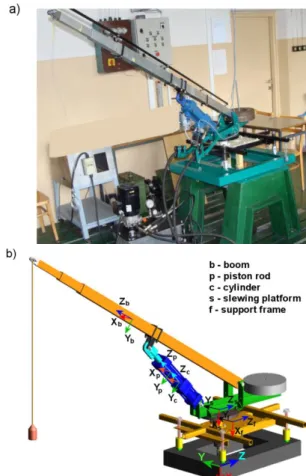
The computational model was developed by using multi-body system analysis software ADAMS based on the real structure of an experimental crane (Fig. 1).
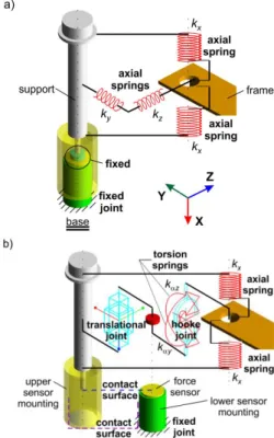
The model included the majority of a crane’s structural com-ponents, which were assumed to be non-deformable except for the supports and the rope. Two variants of the computational model were developed. In variant V1 the kinematic structure of a support system with supports having bilateral constraints was used (Fig. 2a) whereas in variant V2 supports with unilateral constraints were used (Fig. 2b).
Fig. 2. Supports with: a) bilateral constraints (V1), b) unilateral constraints (V2)
The dimensions, masses and mass moments of inertia of the model’s parts were determined based on the measurements of a real structure and the geometrical models of these parts which had been developed by using the Inventor software (Tab. 1).
The stiffnesses and dampings of the axial springs that were used to model the supports were determined experimentally. Since the same set of eight compression springs was used in both variants of the experimental crane to construct the supports, and all these springs came from the same production batch, it was decided that the same stiffness 𝑘𝑥 should be adopted for all of the
axial springs in the computational model. This stiffness was de-termined for a spring which had been randomly selected from the set of springs based on a series of 10 measurements of the de-pendence of deformation on the load, which were made by using a universal testing machine FP10. For each dependence of de-formation on the load an average stiffness 𝑘𝑁 was calculated
based on equation (1) and then a substitute stiffness 𝑘𝑥= 17.25 × 10³N/m was determined by using equation (2). 𝑘𝑁=𝑚1∙ ∑ ∆𝑃∆𝑙𝑖
𝑖
𝑖=𝑚
𝑖=1 (1)
𝑘𝑥 =1𝑠∙𝑛1∙ ∑𝑁=𝑛𝑁=1𝑘𝑁 (2)
where: 𝑁 – measurement no., 𝑚 – number of changes in a spring load, 𝑠 = 2 – number of springs that are connected in parallel to each other in the crane support’s model, 𝑛 – number of
meas-urements, ∆𝑃𝑖 – 𝑖-th change in the load carried by a spring, ∆𝑙𝑖 – 𝑖-th change in a spring’s length.
Damping coefficients 𝑐𝑢 in the supports (systems of springs)
were determined for the directions of the X, Y and Z axes of a reference frame by using the free vibration method. The damping coefficients were calculated by using equation (3) based on the changes in the position of the support frame over time with respect to the base (Giergiel, 1986).
𝑐𝑢=2∙𝑀∙𝛿𝑇 (3)
where: 𝑀 – mass of the system of supports which depends on the location of the sensor of displacements and the direction of movement, 𝛿 – logarithmic damping decrement, 𝑇 – period of damped vibration.
For every direction of movement 10 measurements were car-ried out and the average damping coefficients 𝑐𝑠 were calculated
based on these measurements. In the computational model a damping coefficient was assigned to each of the springs; such a damping coefficient was reduced in relation to the calculated average value proportionately to the number of the supports that were located in the area of the frame’s recorded movement as well as to the number of springs that were connected in parallel to each other in a support. Finally, the following values were adopted for calculations: 𝑐𝑠𝑥= 0.277 × 10³N ∙ s/m, 𝑐𝑠𝑦=
0.47 × 10³N ∙ s/m, 𝑐
𝑠𝑧= 0.59 × 10³N ∙ s/m.
Apart from axial stiffnesses of the springs which were deter-mined experimentally, also the stiffnesses of systems of springs, perpendicular to their axes, were taken into account. Lateral stiffnesses of the systems of springs (𝑘𝑦= 𝑘𝑧= 114 ×
103 N/m) were determined numerically; both the computational model and the calculations themselves were carried out by using the Ansys v11 software and following a method described in Kłosiński and Trąbka (2010).
Tab. 1. Masses and mass moments of inertia of the model’s parts Name of a
given part
Mass [kg]
Mass moments of inertia with respect to the centres of masses of the
model’s parts [kg·m2] Jsx Jsy Jsz Support frame 17.3 0.792 0.567 0.235 Slewing platform 20.2 0.688 0.706 0.128 Boom 4.5 0.937 0.936 0.0025 Piston rod 3.7 0.068 0.067 0.0008 Cylinder 11 0.21 0.21 0.01
Torsion springs were added to the computational model for supports with unilateral constraints. Each of the support screws was connected to the support frame with two torsion springs. They were placed on planes that were parallel to planes XY and XZ of the frame of reference. The stiffnesses of torsion springs were determined experimentally based on tests of the dependence of the support’s angle of rotation on the support frame as a function of the torsional moment. The same value of stiffness for all of the supports was adopted (𝑘𝑎𝑦= 𝑘𝑎𝑧=
78.2 N ∙ m/deg).
At the points of contact between support screws and force sensors, contact joints were applied. As for these joints, the pos-sibility of friction was taken into account (the Coulomb friction model was used).
3. NUMERICAL ANALYSIS OF THE MODEL 3.1. Assumptions for the calculations
The model’s initial position corresponds to a crane being in a state of static equilibrium; the initial tension of springs was taken into account;
Flexibilities, clearances and friction in joints between the model parts were not taken into account;
Flexibilities, clearances and friction in the drive were not taken into account; a constant value of the reduction gear ratio
𝑖 = 20 was adopted;
The rope’s flexibility and the flexibility of the luffing hydraulic cylinder were not included in the model;
A constant step of integration was 0.001 s. 3.2. Calculations
Calculations were carried out for two configurations of the model.
Configuration 1 included a boom inclined to the level at an an-gle of 22º, a crane radius of 1.64 m, a load of 3 kg and a counter-weight of 45 kg.
Configuration 2 included a boom inclined to the level at an angle of 35º, a crane radius of 1.43 m, a load of 1 kg and a coun-terweight of 17 kg.
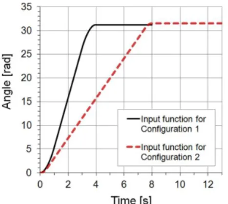
In both cases the distance between the centre of mass of the load and the point where the rope was attached to the boom was 1 m. The rotation angle of the body relative to the chassis was 90º. The kinematic input function was used for the slewing motion. The forms of the functions that were used to describe the input functions are presented in Fig. 3.
Fig. 3. Slewing motion input functions for both model configurations
The calculations were started by checking the correctness of the computational model. In order to do this, first it was checked whether there were no redundant constraints in the model; after-wards, the model was verified. Verification was conducted for both configurations by comparing the calculated support loads with the loads that were recorded during the tests. The results of the com-parison for configuration 2, variant V2, are shown in Fig. 4. It was found that the model properly mapped the real object and the visible differences between characteristics were due to the omis-sion of the flexibilities of particular parts as well as the flexibilities of connections, the friction and clearances in the connections, and most of all due to the omission of clearances in the drive.
Fig. 4. A comparison of support loads for configuration 2, variant V2 with the loads that were recorded during the tests
(BLS – back left support, BRS – back right support, FLS – front left support, FRS – front right support) 3.3. Results and discussion
This paper presents an evaluation of the impact of the kine-matic structure of the support system on the trajectory of the load, the speed of rotation of the body relative to the chassis and the support loads.
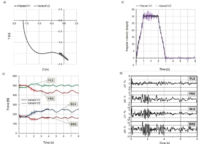
Calculation results for configuration 1 of the computational model are presented in Fig. 5. A dashed line was used for variant V1 of the model and a solid line was used for variant V2. Fig. 5a presents the trajectory of the centre of mass of the load and Fig. 5b shows the changes in the speed of rotation of the body relative to the chassis. The distribution of the support loads is shown in Fig. 5c whereas Fig. 5d presents a quantitative comparison of the changes in variant V2 support loads in relation to variant V1.
The calculation results for configuration 2 of the computational model are presented in the next four figures (Figs. 6a-d) in the same way as for configuration 1.
Based on the calculation results (Figs. 5-6) it was found that:
A change in the kinematic structure of the support system does not lead to significant differences in the load’s trajectory regardless of the configuration and input functions.
The speed of rotation of the body relative to the chassis is non-linear for both variants of the model in configuration 1 and for variant V2 in configuration 2. Moreover, this speed undergoes constant changes and these changes are consi-derably greater for variant V2 than for variant V1.
The changes in the speed of rotation of the body are closely related to the vibration of the support frame which is caused by the horizontal displacement of the supports. Due to the additional degrees of freedom these vibrations have larger amplitudes and cause greater speed changes for variant V2.
An increased number of the degrees of freedom of the support system, in particular the introduction of the possibility of the supports sliding against the base, contributes to the occurrence of short-term (impulsive) variations in the support loads.
The maximum increase of the support loads, which is related to the change in their kinematic structure, does not exceed 14.7% for configuration 1 (Fig. 5d) and 13% for configuration 2 (Fig. 6d).
Fig. 5. Calculation results for configuration 1: a) a trajectory of the centre of mass of the load, b) the speed of rotation of the body relative to the chassis, c) a distribution of the support loads, d) a percentage comparison of the changes in variant V2 of support loads (ΔN) in relation to variant V1 (FLS – front left support, FRS – front right support, BLS – back left support, BRS – back right support)
Fig. 6. Calculation results for configuration 2: a) a trajectory of the centre of mass of the load, b) the speed of rotation of the body relative to the chassis, c) a distribution of the support loads, d) a percentage comparison of the changes in variant V2 of support loads (ΔN) in relation to variant V1 (FLS – front left support, FRS – front right support, BLS – back left support, BRS – back right support)
4. SUMMARY AND CONCLUSIONS
This paper presents the results of numerical analyses of the computational model of an experimental crane which were carried out in order to evaluate the impact of the support system’s kinematic structure on selected kinematic and dynamic quantities of a crane. Two variants of the model were developed – one with supports with bilateral constraints (V1) and the other with supports with unilateral constraints (V2). The stiffnesses and dampings of the supports were determined experimentally. The model did not include flexibilities or clearances in the connections, except for the supports.
On the basis of the numerical analyses, it was found that:
A support system with unilateral constraints introduces multi-ple distortions of time characteristics of the monitored kine-matic and dynamic quantities. These distortions are caused by the possibility of the supports moving relative to the base (slides in the clearance area) and by impact loads which are caused by the interaction between mountings of force sensors (the upper one is connected to the support screw and the low-er one to the base). The maximum excess of the support loads, which is due to the above-mentioned causes (Fig. 5d), does not exceed 14.7% of the value which was obtained for a system with supports with bilateral constraints.
The time characteristics of selected kinematic and dynamic quantities which were obtained for variant V1 of the model, with the same input functions as those which were used for variant V2, are almost completely free from distortions. At subsequent moments of time, particular kinematic and dy-namic quantities assume values which correspond to the av-erage values that were determined for the model with unilat-eral constraints.
Although a support system with supports having bilateral constraints is inconsistent with a crane’s real support system, it can be used in experimental models. Both kinematic and dynamic quantities assume proper values for this variant of the model under the condition that the input functions that are used for the motion are chosen so that the structure does not lose its stability (so that no fictitious forces appear in the model).
On the basis of the calculations it was found that an increase in the coefficient of friction between support screws and the base has a positive influence on the dynamic loads of the supports – distortions of time characteristics are less frequent and the load changes of the supports are smaller relative to the loads in the system with bilateral constraints.
REFERENCES
1. Araya H., Kakuzena M., Kinugawab H., Arai T. (2004), Level luffing control system for crawler cranes, Automation in Construction, 13, 689–697.
2. Blackburn D., Lawrence J., Danielson J., Singhose W., Kamoi T., Taura A. (2010), Radial-motion assisted command shapers for nonlinear tower crane rotational slewing, Control Engineering
Practice, 18, 523–531.
3. Cha J.H., Roh M.I., Lee K.Y. (2010), Dynamic response simulation of a heavy cargo suspended by a floating crane based on multibody system dynamics, Ocean Engineering, 37 (14-15), 1273–1291.
4. Geisler T., Sochacki W. (2011), Modelling and research into the vibrations of truck crane, Scientific Research of the Institute
of Mathematics and Computer Science, 1 (10), 49-60.
5. Giergiel J. (1986), Damping of mechanical vibrations (in Polish), Wyd. AGH, Kraków.
6. Jerman B., Podrzaj P., Kramar J. (2004), An investigation of slewing-crane dynamics during slewing motion—development and verification of a mathematical model, International Journal
of Mechanical Sciences, 46, 729–750.
7. Kilicaslan S., Balkan T., Ider S.K. (1999), Tipping loads of mobile cranes with flexible booms, Journal of Sound and Vibration, 223 (4), 645-657.
8. Kłosiński J. (2005), Swing-free stop control of the slewing motion of a mobile crane, Control Engineering Practice, 13, 451–460. 9. Kłosiński J., Trąbka A. (2010), Frequency analysis of vibratory
device model (in Polish), Pneumatyka, 1, 46-49.
10. Maczyński A. (2000), The influence of crane support flexibility on load motion, 4th EUROMECH Solid Mechanics Conference, Book
of abstracts II, General sessions, Metz, France, June 26-30, 519.
11. Mijailović R. (2011), Modelling the dynamic behaviour of the truck-crane, Transport, 26 (4), 410–417.
12. Paszkiewicz T., Osiński M., Wojciech S. (1999), Dynamic analysis of an offshore crane on offshore installations, 4th International
Offshore Cranes Conference, Stavanger, Norway, April 26-28, 2-38.
13. Smoczek J. (2014), Fuzzy crane control with sensorless payload deflection feedback for vibration reduction, Mechanical Systems and
Signal Processing, 46, 70–81.
14. Smoczek J., Szpytko J. (2012), Fuzzy rules-based approach to estimate the availability of transportation system, International
Journal of Intelligent Systems Technologies and Applications, 11
(1/2), 117-137.
15. Smoczek J., Szpytko J. (2014), Evolutionary algorithm-based design of a fuzzy TBF predictive model and TSK fuzzy anti-sway crane control system, Engineering Applications of Artificial
Intelligence, 28, 190–200.
16. Sochacki W. (2007), The dynamic stability of a laboratory model of a truck crane, Thin-Walled Structures, 45, 927–930.
17. Sosna E. (1984), Influence of flexibility of support system on dynamics of the telescopic mobile crane (in Polish), Praca
doktorska, Politechnika Łódzka.
18. Terashima K., Shen Y., Yano K. (2007), Modeling and optimal control of a rotary crane using the straight transfer transformation method, Control Engineering Practice, 15, 1179–1192.
19. Trąbka A. (2014), Dynamics of telescopic cranes with flexible structural components, International Journal of Mechanical Sciences, 88, 162–174.
20. Trombski M. (Editor) (2003), Control algorithms of telescopic crane
operating cycle (in Polish), Wyd. ATH w Bielsku-Białej.
21. Uchiyama N. (2009), Robust control of rotary crane by partial-state feedback with integrator, Mechatronics, 19, 1294–1302.
22. Uchiyama N., Ouyang H., Sano S. (2013), Simple rotary crane dynamics modeling and open-loop control for residual load sway suppression by only horizontal boom motion, Mechatronics, 23, 1223–1236.
23. Wu J.J. (2006), Finite element analysis and vibration testing of a three-dimensional crane structure, Measurement, 39, 740–749.