'.'
,
"" '
~.'Ftj
7
7t,
r"
\-~ ....FJ.na.l Report Ulder
Contract lio.
AF 19 (60')- 204l"Development of an Acous't1c
Delay Line for Dig1 tal.
storage"
The Research Reported in tb.:18
dOZum
t bas been sponaa:red b;ythe Force Cambridge Research
Cell ~. A1r Research and
Devel.op-ment
Cornrn8nd
~FERRAllTI ELECTRIC,
INC.
30 ROCKFEu.ER PLAZA
NEW YORK 20, N.Y.
(i
i
'. I' .;:\ .
, ' \ . -~ .
,·s 1. 2 5 4. 5 6 7 8
"'
...
8.l.8.2
0
8.58.' 9 l.O I I 12 13
o
L.
.. : ... , .TABLE OF CONTENTS
S~
LIST OF SYMBOIB
ABSTRAC1'
IN'l'RODUCTIOB
BASIC MAGNETOSTRICTIVE DELAI LINB
}(AGNETOSTRICTION
TRANSDUCER msIcm
PROPAGATION OF ACO'lSTIC WAVliS
CHOICE OF MATERIAlS
TEMPERATURE COEFFICIENT OF DELAY
ATTENUATION
LINE SUPPORT MATERIAL
ACOUSTIC TERMINATION
MODE CONVERTING JUNCTION PRACTICAL DESIGIf
TESTING
CONCLtSION
APPENDIX: a) Figure. 1 tbrouab 25
1:» Referenc ••
c) Ddetr11:>ut1oD Lilt
PAGE BUMBER
1.
5
,
89
,-," 11
17 20 22 26 28 29 30 55 54 ~
:""'r-, t
I
;:,)kf.:-';.';~:" ?,.~,,"~. ',S" U .\ : "'." ",". :J'" ,.",?,'"",
. ' ' ;
m
,','
.,
o
o
I
o
UST OF SYMBOLS '.
A - Cross Sect10nal Area of Tape: em?
B - Fl.\:..x Density:
Gaj-S
cL _ wngitudinal Phase Velocity of Sound 1n a Straigbt Wire: em/lec.
cT _ Torsional Pilase Velocity of Sound 1n a Stra1gbt Wire: em/ ••
e
E
-
Youngs Modulus of Elast1city: f1:/nea/ cm2f
-
Frequency Cycles/SecondF
-
Force: DynesH _ . Magnetic Field: Oersteds
•
I
.-
r.t>ment of Icertia per unit lengt.b: g-em\
k
-
Radius of Gyration: emkc
-
£lectro ~~an1cal Coupling FactorM
-
Bending r.t>ment: Dyne-emm
-
Miss per un! t length: g/emN
-
Number of Digits. in a Storen - Number of '.!apes on a wngi tud1nal-Tors10nal Mode Transformer
R - Radius of Curvature of Wire: em
r - Radius of Wire: em
S _ cross Sectional Area: em2
T _ Temperature: Degrees ·Centigrade
t ..
Tim.:
SecondaT
-
Time Delay : Secondav L
-
Phase Velocity of wngitudinal Stress Wa.v •• :cm/I.C.
v
T
-
Phase Velocity of Torsional Stress ila.ves: eta/sec.1
-
.IAngtb : em·z
-
Impedance I egaun1ts
).
-
Wavelensth em-1-/:" ,i~:,:}'.' ", .. ).~j>?,:
# l ' t ' b · ' 1
o
'0
LO
... Current : Amperes
Jl
=
Magnetostr1ct1on Stress Constant QyneS/Gauas cm2ILj ... Incremental. Permeabil1ty
1'0 ..
Permeabil1 ty of Free Space: Gauss/OerstedP
-
Density :s/
CJA3P
11/ ... Renection FactorV - Fb1sson's Ratio
l ' r .-, ....
o
o
2. ABSTRACT ....
This report describes investigations into an ul.trasonic delay line using
magnetost.riction drivers, with the following resul.ts:
a) Elcperimentation with materials and heat treating has shown the possibility
+ .
of achieving temperature coefficients of deJ.e.y of approximately - 1 part
per million per degree centigrade.
b) Design criteria are discussed for
1. Transducer
2. Reduction of dispersion
3. Line length
4. f.bde converting Junction
c) Q,lant1tative figures are given for attenuation
~
dispersion.d) Pract1cal construction techniques have been worked out for a finished line •
• ) 'lbe torsional mode has been shown practical. for delays of 5 ms., a~ a
I
storage capa.ci ty of 2500 bits.
f) Lines capable of operating at 1 megacycle bit rate and 500 mic!oosecond d.el.ay
have been achieved.
g) Techniques of measurement are described.
h) A recirculating store has been designed and fabricated to demonstrate the
operation of a delay Une at a digit rate of 500 kc_/sec.
-
-·W
o
o
· ' t ' · " ' 1 ' 'z
3. INTRODUCTION
A system sui table for the storage of digital information can be made v:I. th
any delay element which has a delay time equal
to
the length 01' pattern to bestored and wlllch 1s sufficiently non-dispersive. ThU8 a pulse vri tten into 11;
at anyone digit time must be distinguished unambiguoualy at the output,
wi thout interference from pulses vri tten in at other time.. A rec1rculat1q
circuit can then standardise and retime the output pulaes 80 that tbey can be
written back at the input and thus stored indefinitely without los ••
In order to avoid expensive 1nstallat10ns, it 18 desirable that the delAy
element be unaffected by environmental condi t10na such as temperature variation,
vibration and stray magnetic fields. In addit10n 1t 1s essential. tbat the del..q
element be cheap, of reasonable size and readily fabri~ted. -The overall loa.
in the device should be lo'Wj and input and output impedance. should be compaUbla
with existing circuit techniques.
tn.trasonic delay lines have been in use as a l3.1g1tal storage element t'ar ''"'
some considerable time. In all. cases the delay 1s acb1eved by utlllzing the
relatively low velocity of propagation of acoustic waves in a solid or liquid
medium. 'Dle three most widely used media are:
(1) M!rcury
(2) Q1a.rtz
( 3 ) Wire or tape
Mercury delay lines are cumbersCX?e and Buffer from a large temperature
coefficient of delay (300 x 10-6 per degree C.)
Q,lartz lines are sma.ller than those using mercury I but prec1l10n
a:r1n41nc
1s necessary in their manufacture and they also suffer fram a large temperature
coefficient of delay (75 x 10.6 per degree C.)
Wire type delay lines offer several distinct advantages over the mercury
and quartz types. 'nley are more flexible 'With respe.ct to packaging, are ·l1sht
-4-I
-rtf t r t t t
o
o
in weight, robust and cheap. In addition, by
su1tab~e
choice ofmate~ial.e
an
extremely ~ow temperature coefficient of deay may be reaUsed, thereby el1m1n-ating the need for temperature contro~ of the environment in vh1ch.they ate used.
This investigation bas been restricted to the u •• ot wire as
th.
de:a.q medium.In addition to the de~y medium, it is necessary
to
prov14e some methocl of converting from e~ectric~ to mecban1c~ energy at the input 1n orderto
launch the acoustic waves in the deay medium, and at the output the acouat1c waves must be reconverted to e~ectric~ energy. The tvo well
movn,
methode ot making such a transducer depend upon either the piezo-electricphenanenOll or the magnetostrictive phenomenon.'nle piezo-electric effect reates to the fact that stress i8 su:ffered by
'"
. ~
certain types of crystal when subjected to an applied vo~tage. ~s type
ot
transducer is dif1'1~t to manufacture because of the probam of attacbirl&
the
small crystal to the deay medium •. Large' voltage signals are required at theinput mak1 ng them unsuitable for use with transistor circui Uy. To offset th1s
however, it is possible for a piezo-electric transducer to handle digit rate.
as high as 5 megacy~es/8ec.
Tbe magnetostrictive effect refers to the change in ~ear dimensions
ot
a material when subjected to a magnetic field. Magnetostrictive transducer. are more flexible in design, easier to assemble and are much more rugged than
the piezo-ele-ctric type. The upper l.1m1t ofd1g1t rate for these transducera i8 around 2 megacy~es/sec. It i8 not necesGary to u •• magnetostrictive materi~ for the de1.ay medium and thus each material can be chosen independently for
optimum characteristics. T.!le complete delay line is then formed by veld1ngthe line material to the magnetostrict1ve material.
-o
o
\
Only magnetostrictive type transducers will be considered in ~s \,'eport,
and these will launch and detect long! tudinal stress waves in the material
under the transducer.
The energy in the delay medium can be propogated as longitudinal, shear,
or torsional waves. When longitudinal waves are used, the transverse dimensions
of the del~ material must be small compared to. the wavelength in order
to
avoiddispersion due to intermode coupling from Poisson contraction effects. ~.
necessitates the use of fine wire, which presents considerable
handl1n&
difficulties.
Wben torsional waves are used there is. no spurious coupling and no
disper-sion occurs in a medium of circular cross section for any diameter. I t is
~.
----~t howev.!r I ~ launch and detect torsional waves at a _diameter greater
than the wavelength, and it is this that de~m1oe~!...maX1mum diameter
--
.
~ ---~---...---~-...,--
. forthe delay material. . ...
---
The rate of propagation of torsional waves is appreciably slower than forlongi tudinal waves in the same material. This results. in a shorter-length
ot
wire for a given delay time when using torsional waves.
In order to accomodate a delay greater than about 100 microseconds in a
practical size of package it is necessary to coil the delay ~terial. 1be
resulting curvature introduces phase dispersion for .botb longitudinal and
torsional modes of propagation. In the case of longitudinal waves there 1a DO
method for avoiding this dispersion, whereas for torsional propagation the
dispersion can be virtually el1m1nated by using material whicb 18 natural.ly
straight.
These points clearly indicate that the torsional mode
ot
propagation inthe delay mediUl!l confers several ad'/antages over other modes I and 1 t baa been
adopted in this1nvestigation.
.
6-• . . ! ,
.
,J
.-o
o
tt" Ri'lf
It will be remembered however that the transducers launch longitudinal
pulses in the magnetostrictive material. 'Ihus some means of converting fran'
longi tudinal to torsional stress .. .-avea and vice verGa. is required. A simple
yet efficient mode converter has been developed for this purpose.
Reflections from the ends of tha delay line have been lll1nimized by the
choice of suitnble termination materie.l.s and :nethods. In addition, the erfect.
of line support ~t~rial on pulse distortion has been investigated.
A more detailed treatment follows, as to the various phen~~ena investigated
an~ their.interrelationship in producing a practical digital storage element.
7-o
o
BASIC MAGNETOSTRICTIVE DEIAY LINE(2)
'lhe simplest form of a magnetostrict1ve line (Fig. 1&) consists of a piece
of vire, made of e. material exhibiting the magnetostrictive effect, threa.ded
into 2 amall coils spaced a distance 1, (eqUl. valent to a delay t') apart. An external biasing magnet i8 provided for each transducer, supplying flux parall.el
to the longitudinal ax1a of the wire.
Application of a current pulse to one of these coil.a (the "drive"coil)
results in the propagation of two equal longitudinal stress pulses travell1.ng
in opposite directions. One of these pulses travels down the. line in the
direction of the second or "receive" coil. The other pulse i8 absorbed by a
sof't rubbery termination. The traveling stresa pulse moves with the velocity
of sound in the solid and is detected upon passing under the second coll by
\ .
\ .
means of the inverse magnetostrictive effect. A second termination prevents
reflections !rem the other end of the line.
i
Further analysis has ahow the desirability of making Unes using the
torsional mode (Fig. lb). Thi8 involves generating tbe pulses 10ng1tud1~,
letting them travel through tapes to a mode converting Junction. 'lben'(upon
conversion to the torsional mode) torsional vibrat10ns are permitted to travel
al.on&
the wire Une t i l l they reach a second mode converting junction. FrcIIlthis point, ~pon being transformed back into longitudinal stress waves operation
i8 a1 m1l.ar to the reeei ve portion of the line previousl;y described. Actual.
torsional lines are packaged with the wire materiaJ. .formed into a sp1~a.l.
'!he delay i8 g1 ven by:
(4..1)
wbere 1. &.
1z
are the l.engths of the metal. tapea associated with the driveand receive transducer., vL 18 the velocity of propagation in the longitud1nal
mode .. l.3 i8 the length of the wire material. and VT 18 the velocity of
propagation in the torsional mode.
-8-I
-5.
o
o
',' ,. ':.".
MAGNE'l"OSTRIC'l'lOIf (,)
The magnetostrict1ve effect occurs in ferromagnetic matarial8 sueh as
irOD,
nickel, cobalt and certa.1n alloys. A magnetic field applied parallel
to
theaxis ot a rod. of such maUtrial causes a ehange in its length. It a field
." .
B -
i:i
i
N/l Oersteds is generated by a coil of lengtb 1 and turns If,'tihe
fluxdensity B within a piece otthe line material inserted into the coil will be
B -
I~'''''
i
1/1 Gaus.The value ot
po.
is a function.of the core mater1al, its treatment, themagnetic field and the temperature.
A strain
81/1
will be induced by the field B. A plot 0,1' the strain ver_uafield strength and flux dens1 ty is sbown for Nickel and ~rmall()y in Figure 2a
and 2b. \
It 1i known that the s1gn ot the strain is independent ot the direction
ottbe appUed fifllld. This would indicate that. the strain is an even tunction
,
.ot the magnet.lc field. Eltper1ment has sbown that the tollov1lig relatlO118hip
holds within the range ot operation:
81/1 _
cBo 2 (5.1)where Bo 18 the polarizing flux density and c is a material cODstant.
Difterentiating the strain with respect to the tluX density Bo gives:
d (81/1)- 2cBodB (5.2)
I t we consider the incremental stress as a function ot tbe incremental flux
denSity
dBo,
for a clampea rod (assuming BooU'_ lav)(5.3)
Where 2cBoE
=A
tbe magnetostriction stress constant indynes/gaus. cm2~Nickel contracts Vi th increasing B" so its
A
is negative. Permalloy on theother band" expands wben magnetized,,' and theretore
A
1s positlve.
-9-t
ht t . ': ;~. , : "
.. ';f ... "0":' ~ ,~_:"".~ •. ~~~"..r..." • ..ar~~':L :;~V~'~;r'~~ .,~
..
- ",c:i··
It eaJl.be .bown that the induction 01" a polar1zing tlux in a masneto'ltrict1ve
material lover. the value 01" Young'. modulUl~
I' -
(l-k~)
I
kc 18 the electromecbaDical coupl11l$lt tactor:
kc - 2CBo../
1'1
1'0
B (5.5)'lbe degree 01" coupl1ng i. tbus dependent on the operating point Q11 the
magnetization curve 01" the core material. !hil point may be altered tor
PftA
eJtternal conditions by annealing. In practice 1 t 18 found that the Dickel tape.
used can be annealed to a sat18tactory degree by beating tbe.repon to be .place.
under the transducer coils tor approximately 30 seconda in air I at a teaperature
01" about 7000 C.
-10-(
.
\
.':'-,~
(.r,· ~" .. " .. ,.--' '-. _~~k~\':~:'#:,!t'-l :
6.' TRANSDUCER DESIGN
Consider transmit and receive transducer coils of effective length.
_ 1, and 12 where 1, 18 greater than or equal to
.tz.
o
L.O
Consider a current applied to the transmit transducer. The reault1n&
current. flow 18 shoYD 1n 1'11. 3&. If the flux changes by a small amount
8_
then byt.he masnetostrictive effect, a dist.urbance over t.he length
1,
reaulta.Bence a stress vave of length 1, is propagated. In time T thi. will travel a
distance VT and if t.he flux continues to change for·a similar .tiM T .the
result1n& stress vave will be 1, + VT. It is also apparent that the st.re ••
distribut.ion is a fUnct.ion of d;/dt. The distribution of the stress along the
line is shoYD in Fl,. 3b. Aa the stres.vave passes t.hrouah the receive coil..
the nux ~2 produced by 1t., which is approximately proportional to atres., aDd.
integrat.ed over the coil length is as .hown in 'Flg. Se.
'lbe resulting out.put. is proportional to d.fJ2ldt and is shown inFl,_ 3d._
In practice 12 18 chosen such that an output, as shown in.I'1&. 3e 18 obtainect.
I! a rectangular input current. pulse of fin! te length is now applied to·~
trana&1 t transducer then the resulting current flow is &8 shoYD in P'1g.
st
and the output voltage as in I'1g. Sg. By reducing ~e width of the input pulae,
the two p&rts ot the output can be combined. rus is the output yavefora usuall1
required tor di&1 tal storase. However a non return to zero type of pattern can
be used and the output wavefora vh1ch is shoYD in I'1g.
's.
utilized.AD improvement in efficiency, and a better utilisation of the available
bandwidth may be achieved by combining cons.cut.ive ·ones· as Illustratect in
1'11. 31. 'D1e "resolut.Ion" or min1mWll dig! t. spacing, which such a s,.stea will
accomodat.e may be defined as the separat.ion ot the two positive lobes of the
ai~al in I1g. 31 to ensure that two consecutive ones are coablned without
pattern senaltlv1tl.
-11-j
-1
o
o
r&d t {"
Consider the combinations of the positive and negative lobes in FiC. 34
by the choice of 12 (as discuss.ed in the previou8 section). For minimum separatioo
of the two peaks in the resulting di-pul.se, 1t 18 apparent that:
l' Z .. 1/2 (1.1.,
+ T)'Ibis flhould equal t/2 vbere t - di81 t spac1na
i.e.
1/2 (1,/"
+ T) - t/2or l.1v + 1" - t
1" - t/2
l,/v - t/2
FraIl
6.1
and6.2
and 1fl' 2.
Iv -
t/2
Also
Therefore I, - )./2
l' 2 - ). /2
Bence, eacb coll sbould be one bal.f a vave1ength long.
(6.1)
(6.2)
(6.3)
(6.4)
(6.5)
(6.6) (6;7)
The length of the transmit transducer 18 defined
trcm
equation(6.4) Il/v
=
t/2. 'Ibe inductance of the receive transducer DlUSt be able toaccomodate the minimum rise time associated with the output signal. 1.e. t/2.
Bence, each transducer assembly can be s1m11.&r. The object of the transmit
transducer Is to convert the induced magnetic energy into mechanical (acoustic)
energy. 'Iberefore good electromechanical coupling is desirable, (in practice
efficiencies of 1~ are acb1eved). A typical insertion 10s8 for one transducer
18 20 db.
-12-
.-I
-._;tJ',,":--'-- *t t m
-.---Transducer. bave been made
ot
varying lid ratios, total numberot
turna etO •.To eneure good coupl1ng it 18 desirable that the col1 must be wound . . clo.e . .
posslble to the magnetostrlctlve materlal. The same argument CISA be appl1ed
to
.4C)
the receive transducer, only here the object ls to convert the .echanicalenergy, which baa been propagated, back into electrical energy. Tbia demaD"
o
that the magnetic
nux
l1nk. the whole winding and again a closely wound coU.18 des1rable.
Once a satistactory . .
_....0...-_
~anical. ___
design ~__
ot
~__ transducer_
baa been acb1eve4,_,
it 1. possible
-
to improve operation by tuning the electromecban1cal circuit~-
.---
..by means
ot
a capacitor shunted acros. the transducer coil. ~ value can:---~~--~~~~~.~~~----~--- ~
. be chosen to re.onate vi th the coil at the frequency
ot
operatiOD~ A .hUllt damping reaistor may then be .used, and chosen to provide critical dulp1D& •.. ·Another cause
ot
distortion 11 improper magnetic biuingot
the tapes.For proper operation the stress pulaes in each
ot
the istrip• ahoul.4 be 111 exactanti-phase. 1b18 18· accomplished,
tor
small signal operation, by biaaina toabout 60~
ot
8aturation. Operation about this point produce • • tre •• pula~.8ymmetrically a~out the biasing point thus permitting "push pull- operatloa
ot
the tapes. In addition it is required that the transducer coila be tlW . . . .time delay ava.;y
fre.
the Junction. As the bit rate goes up the 108. o'tresolution introduced by a given misalignment
ot
the coila alao goes up. I1gures4. & 24 illustrate the relationship
ot
the colls to the line, and also .hov a typical tran8ducer holder •. It 1s a well known 'tact that the physical lenstbot a coil 1s not equal to
.,
its ettective length. SODle allowance IllUst be made tor the
nux
trlng1na ateach end ot the coil. This effect has been meuured directly u 'tollow.
'lVo U'ansciucer coils, wound on Tetlon tublng
ot
outside diameter 0.04.7 inches,veretbreaded aide by side onto a length
ot
nickel strip. The coila coul.cl bemoved tog.ther. ODe ot the coils vas connected to a 500 kc oscillator and the
voltage induced in the adJacent coil was measured. The amplitude of the
4:)
induced voltage was taken as a measure of the end effect ••0
o
The effect measured W&$ independent of coil length, but dependent on the
inside and outside diametera of the coils. Fig. 5 shows a graph of induced .
voltage versus spacing for two coils of mean diameter 0.055 inches. It. 1.
apparent that at spacings of approximately the mean diameter, the induced
voltage, and hence the fringing field is small compared to zero spac1nc.
The conclusion is therefore, that the effective length of a coll 18 the
physical length plus the sum of the two end effects (approx1mate~ a .ean
diameter). If we assume that the exact correction factor i. constant, with1D
80me range of coil dimensions, we can wr1 te :
left
-
1 + KDI (6.8)wbere: DI
-
mean diameterK
-
correction factor1
-
actual lengthleff
-
effective lengthWe see therefore, that a reduction in coll length and mean diameter sboul.d
improve the frequency response. It is also apparent that coila of var10ua
dimensions can produce the same frequency response.
It 18 evident fran the above experiment that the measurement as performed,
was dependent on the mutual inductance of the two coils used. Utvo coila wi t.h
rectangul.ar sections are spaced co-axially, then apprax1mate value. of 1IlUtNal.
inductance are found ... follow. ( 6 )
where N - number of turns on each coil
DI • mean diamet.erof coil
FI- correction factor
-14-(6.9)
. &
!
o
o
:;,
It has been found experimentally that the inductance of the coilS changes by .
approxlmatelylOJ due to insertion of nickel tapes. For this reaaon the air
core f'ormula is used.
FI can be expressed approximately (for the region of operation) as an
exponentialf\mctlon of the mean diameter and the distance between colla ( rZ )
as
fallon:(6.10)
where r. - rZ Z 2 + ~Z
when r2 ~O
l1a '::
O. 05rD'when r Z
-::: D}Z
l1a -
- O. 05 Z • -'.6 x .'5 N Defrom which lt can be seen that the end effects can be conservatively approximated
•
•by assuming D/2 as the additional effective length per transducer coil end.
Consider a transducer 0.025 inches long and
at
I.D. = 0.047 inche.,O.D .... O.llO inches. This transducer injects a slgn8.l1 microsecond in duratlon·
into nickel "tapes. Using the criteria previously developed and as~um1ng the
veloci ty of propagation in nickel to be 5.28. microseconds per ineb, the effect! va
length desired in nickel 18:
lef'f - 1/2 x 1/5.28 inches/microsecond
inserting above values into (6.S) gives
1/2{S.28) - .025 + K (0.04.7 + 0.llO)/2
and K - 0.95
(6.1,1.)
(6.12)
It must be pointed out hovever, that the velocity of propagation used in the.
above cOCllputation i. not exact, as annealing and magnetization affect the elutic
modulus. Both tend to give a modulus that is lover than normal, therefore. &
lover velocity results. This IDe8.nS that the tr811.ducer'vould need a lover
ef'fect1velength in order to provide equivalent performance. In· general these
effects could cause a maximum change ·of 50~ 1n the velocity
ot
propagation •...
. \-15-.,;
o
o
i/O
-",,' H t ' tt ttl
in practice the change appears to be of the order of a few per cent.
As the transducer coils are made in a simple form, vi th no attempt to
complete the magnetic circuit outside the vire, it 18,
ot
course natUral toexpect the end effects mentioned previously. In order to 'm1n1m1ze thi. effect it is therefore desirable that the magnetic circuit of at l.east the
transmitter coil 8hould be completed by some material suell as " Ferroxcu'be" •
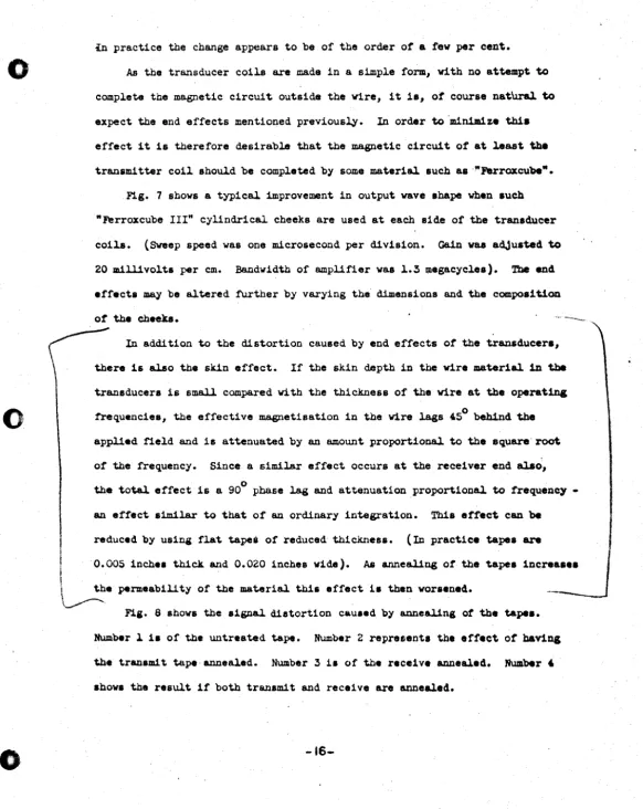
Fig. 7 shows a typical improvement in output wave 8hape when such
"Ferroxcube
III"
cylindrical cheeks are used at each side of the tran8ducercoi~. (Sweep speed was one microsecond per division. Gain waa adjusted to
20 m.1ll1volts per em. Bandwidth of amplifier was 1.3 megacycles). Tbe end
effects may be altered further by varying the dimensions and the composition
of the cheeks.
In addition to the distortion caused by end effects of the transducers,
there is alao the skin effect.
If
the skin depth 1n the wire material in tbetransducers is small compared wi. th the thickness of the vire at the operat1n&
o
frequencies, the effective magnetisation in the wire lags 45 behind the
applied field and is attenuated by an amount proportional. to the square'root
of the frequency. Since a similar effect occurs at the receiver end alao,
o
the total effect is a 90 phase lag and attenuation proportional to frequency
-an effect s1m.1lar to that of an ordinary integration. This effect can be
reduced by using flat tapei of reduced thickness. (In practice tapes are
I
0.005 1.ch ••_ell.
and 0.020 i.cbe. v1de). . . """eal1ng of the tapes ,.cre ....i the permeability of the material this effect h then worsened.
~.
Fig. 8 shows the signal distortion cau.ed by annealing at the tape ••
Number 1 1& of the untreated tape. Number 2 represent. the effect
or banns
the transm1t tape annealed. Number 3 1. of the receive annealed. Number'
.how. the result if both transm1t and receive are annealed.
[image:18.630.12.594.29.761.2]-16-o
o
:L.
IH Ilk ,,·pw
. "' . .';, ' ... ;
7. PROPAGATION OF ACOUSTIC WAVES
(~)
(S )The velocity of propagation of longitudinal Yav •• in .'b'a1gbtv:l.re is
(7.~')
The derivation of the equation ignores 1ntermode coupl.1ng by means
ot
PcbsOilcontraction.
The velocity of propagation
ot
torsional waves in straight v1re 18 siTeDb7:
(7.2)
E. - E/2(~ + cr)
v
-Iv
L - ../"'i/~2-:-( l~.-cr-:)~and .ince
tT ~ 0.3
(7.S)
Where the diameter
ot
the wire is comparable to the sound vavel.eDgtb, thepbaae velocity of longitudinal waves may be described by thetol.l.ov1n8equaUOIl.
(7.')
CUly by U8ing thin w1re can the phase distortion descr1bed by (7.') be .inf_hed.
51nce torsi~ strain in a circulAr wire 1s not accaapan1ed by 8ZJY other atra1n,
a torsional pulse can be transmitted along a 8traight cyl1ndr1ca,J. bar vi tbou't
dispersion as long as the bar i8 perfectly elaatic.
o
t t ' ... : ttt hr. t
: .. :;>;
.A typical wire material ba8 a delay
ot
approximately 5 in1er08eeonda per1neb 10 the lonai tudinal mode and 9 microseconds per inch in the toraioaal
mode. A 5 millisecond line woul.d thu8 require 500 inche. or approximately
40 feet of vire, i t u.ed ~rsional.l.y anel tvice that i t used ~ong1tud1n&ll.y.
In order to achleve large delay. in a reasonab~e package it 11 tound neces.ary
to coil the wire into It. .p1ral. If' th18 is done another form of di.perl1on
will be produced.
The phaae Telocity of ~ongitud1nal wave. 1n a unitormly curved wire 1.
glven by
(7.5)
Dispersion due to thi. 11 serious in long delay. and can be avoided only by
increasing the radius
ot
curvature.~e phase velocity of tor.ional waves for curved wire 1. given
by:
(7.6)
llbere
lin
1. the natural., and R the forced, radiu. of curvature.In this case, malting
Rn
~ge, (i.e. by-using wire which is 'natural.l.y straight,or which baa been straightened after' drawing,) will reduce phase distortion.
~f
Rn
coul.d be made infinite pbaae distortion woul.d be zero'regardles. of R,the forced radius.
R
i . chosen as the ~ge.t value compatib~e-with goodpackaging and the smallest value compatible vi th the elastic properties
ot
the wire.Another
torm
-of dispersion 1s that due to paras 1 tic transverse motion. Wbenwaves which. are pr1ma.rlly longitudinal are propagated along a curved vire, they
are accompanied by e parasitic transverse motion. 1n the plane of curvature.
Similarly when torsional waves travel in a curved wire, the parasit1c transver.e
motion i. normal to the plane of curvature. The supports for the wire interfere
-18-with this motion and produce dispersion. Fbr a given input power the torsional
mode shows less parasitic motion than the longitudinal mode.
o
In practi ce it is posst ble to approximate the conditions requiredtor
min1Jllumphase distortion by straightening the wire atter delivery from themanutacturer
and prior to any heat treating that might be required. Tbe Nt-Span C vire must
be coiled into a maximum diameter of 40 inches to permit insertion into available
fUrnaces. This places a practical upper limit on the natural radius
ot
curvatureof such wire, as heat treating produces a permanent set. For the cue where the
untreated wire will be used in a line Rn will of course be larger.
The principle in straightening wire is that the wire material be taken past
its elutic limit in ever decreasing amplitudes. This is accomplished bypass1na
the wire through a rotating, curved aluminum mandrel vh1ch introduces curvature
into the wire, then introduces one opposite in direction, enabling the vire to
be taken out co-linearly with the input.
ng. 6 demonstrates the-effect of permanently bending the wire. Azl extreme
case is that of a one millisecond line permanently spiralled to a diameter or
4C)
one inch. The picture demonstrates the dispersion produced when variousfrequen-cies arrive at different times, and with different amplitudes.
It has been shown however, that the wire may be constrained to a diamete:L'
or six inches and still provide satisfactory operation over a delay or one
millisecond at aPRRo! one megacycle.
o
-19-
!8.
··0
o
o
CHOICE OF MATERIAlS (3){4) (5)
In general, the line material will introduce variables of the follov1n&
nature.
a) Variation in delay sa a function of temperature for a given line
configuration
b) Variation in amplitude a8 a :f'wlction Of temperature
c) Phase distortion introduced by visco elastic eftect.
d) Variation in amplitude as a function of frequency
e) Elastic l1m1 t of themater1al determines the radius of curvature to which
one can form Une without permanent deformation.
The following discussion on energy losse6 in solids 1s meant only ... a
general guide to thinlt1ng and experimentation, rather than 8.8 an explanation
of spec1f1c phenomena.
llhergy losses of a sound wave propagated through a solid may 'be attributed
to .everal mechan1ama:
~) 'lbermal .trects
2) Rel.a.uUona
3) Scatter1n&
The f1rst mechanism i8 l088 due to neat flow. Thi. i. caused by the
alternate compressions or rarefact10ns caused by the sound wave traveUna alona
the mater1al. This eftect 1a proportional to the square
ot
the frequency_ Inaddition to this 1s the loss due to 1ntergrain heat flow. This 1& due to a
thermoelast1c relaxation loss arising 8.8 heat flow from grains that ~ve
received more compreSSion or extens10n in the course
ot
wave motio& thaD doadJacent grains. This effect occurs below 100 lta.
Losses due to grain rotat1on occur because of the viscosity
ot
theboundary layer between grains. This allows a relative rotation of grain.,
provided the r. laxati on time 18 comparable with the time
ot
the applied torce •.. 20 ..
I
-o·
o
o
,
., .. ; .. ],!.,,: :.\
,~ :
': '
This relaxation time shows a shift as a function of temperature:
Losses due to scatterIng occur because of loss of energy trom the main wave due to the scattering of sound when the sound wavelength 1. of the ·same order as the graIn size.' In the region of wavelength equal to 3 times grain sIze attenuation is proportional to grain size cubed, frequency to the fourth power and inversely proportional to the velocity to the fourth power.
Pbr
shorter wavelengths the attenuation is less frequency dependent and for·wave-lengths less than the grain size the loss 1& independent o~ frequency.
It appears that most polycrystall1ne metals show a linear incre.... of overall attenuation versus frequency.
In
the ultrasonic range in general, damping is strongly increased by cold 'iiork and permanent strain, vbere ... , annealing produces a substantial reduction of the losses. Furthermore energyI lost in the transmission of the ultrasonic wave depends on the. degree
ot
isotropy in the material.lbe losses are particularly small in aluminum, :nagnesium and tungsten
whose elastic constants differ only slightly in the different crystal directions. . Lowest losses are encountered in single crystals and amorphous materials like
fused' quartz. The smaller the grain 61ze of a polycrystalline material the higher the losse ••
In ferromagnetic materials, acoustic losses can be show to be related
to
the motion of walls or rotation of domains in metallic ferromagnetic materials which generate eddy currents. This efrect has its peak at about one mesaeycle for polycrystall1ne nickel rod.
We know experimentally that attenuation in annealed nickel, used
tor
the transmission tapes, is greater than in the untreated nickel.. """;,,,
o
.-
L.
..
.,
results for longitudinal waves can be taken a8 a rougb guide· for expected
results in torsional experiments. The Poisson ratio is generally a function
of temperature, and therefore this must be known in addition to the temperature
dependence of Youngs modulus before one can predict the temperature. coefficient
of .delay in the torsional mode. This discrepancY becomes of great importance
when analyzing the region around 0 parts per million per degree centisrade.
The general procedure has been to make a torsional delay llne of from
:5 to 5 milliseconds delay, and measure the change in delay as a function 01'
temperature from OOC to 6SoC •.
Materials tested have fallen into 2 categories, either those who.e modulus
is a function of chemical composition, or those whose modulus 18 controllable
by heat treating. An example of the first is "Isoelastic" manufactured by
John Chattillon and Sons. An example of the second is "Ni-Span-C", manufactured
byH. A. Wilson and Co. Work bas ~ntered around the Ni-Span-C, as it vas found
early in the experiments that the Isoelastic material attenuated the signal to
an unsatisfactory extent.
Reference to Fig. l.0 shows typical behaviour of the elastic modulus 01' an
iron nickel. al.l.oy. The pOints ·at which the temperature cOefficient 01' the modul.ua
are zero are al.so points at which the coefficient changes rapidly vith
cOmposit-ion, and therefore cannot be used comnercia.l.l.y, as the problem of al.l.oycontrol.
to these tolerances is difficult. One way out of this problem is to utilize the
region of 34~ nickel content, at which point variation in composition vill have
the minimum effect on the temperature coefficient. In the Isol.astic type 01'
al.l.oy, cbromium i. added, to depress the high positive peak. The amount may be
adjusted until the peak is in the region shown by the dotted line of Flg. l.0.
'lbe mechanical. property of these al.loys can be increased only by cold vorkina.
Addition of another al.l.oying element titanium, permits the entire system to be
hardened by heat treating. The result1ng all.oy,Ni-Span-C, has incre . . ed age or
preCipitation hardening characteristics. A sl~sht ch~ge of nickel and titanium
o
o
o
L.
t -, t " j
'" ,.' eo ... ,""," "
content also produces a change 1n the temperature coeffic1entof modulus. 'lb.
final heat treatment adjust. the thermo-elastic coeff1cientto the d •• 1red
value as vell a8 increasing the strength.
It i8 believed that an 1ntermetallic cODlpound of t1 t8n1um and nickel 1.
formed (N1Z'l'1) and this phase 18 d1saolved 1n the 1ron-nickel chromium matr1x.
by rais1ng the alloy to a solutio~ annealing temperature of approximately 1750°11"
to 13500.,. The alloy 18 then rapidly cooled to room temperature (u.ual.l..)' 'by
water quenching) to retain the intermetalllc compound in a super saturated
condit10n. A 8ubsequent age-hardening treatment 1s performed 1n the ranae of
UQO°l' dur1ng wh1ch the 1ntermetallic compound 1. prec1pi tated fro. the matrix
to bring about marked change 1n phyaical properties.
The first 8tep leave. the material 1n 1 ts .ottest" most duct1le' state. III
thi. form cold york 1a performed to produce change 1n shape and other phye1cal
characteristic.. Cold worked material responds toprecip1tat1oc
b&rden1Da
tr.atment more rapidly than an unstrained alloy, .0 that time required for
ace
hardening can be reduced. The first step 18 usually perfo:raed by the supplier
of the Yire material. The second .tep of the heat treatment, age harden1na, 18
accomplished by bringing the mat.erlal to the UOOo, - l.350°}l" range at8D7
[image:25.640.20.600.11.763.2]convenient rate, and then cooling at a convenient rate.
Figure I I .hov. the relation between the aaeha:rdening temperature" tbe
adJusted chromium plus titanium content, and the re.ul.t1ng tbemoelaat1c
coefficient. AdJusted chromium plu. titanium content - Cr +
('r1 -
'C) vbereC i . the percentage
carbon.
In general 1 t is advisable to remove internal .tre.... re.ul.t1D& trca colA
yor~ng by sui table treatment prior
to
age hardening. Internal .tre . . . . accelerateag. hardening. Varying interna.! .tre . . es can produce varying decre ••
ot
aphardening and thus lead to slight variation. arter heat treat1o.a. A .tre ••
reUev. a.nneal at 750°"
trom
one totour
hour., can be usedto
ailWl1z. thi.o
o
.-
...., ( ' : ! "
': ... ,."
The fabrication of 5 millisecond delay 11nes requires single pieces
of
N1 Span C wire about fifty feet 1n length. 'lbe vire material used (0.030")
in diameter must be straightened (as dictated by the previous analysis
ot
dispersion) prior to winding into the spiral shape used. Stra1sbten1ng takes
place after the solution annealing and the cold work proces8 reqUired to reduce
the vire to required diameter. Heat treatlng the vire mater1al the second
t1me,
increases strength and bardness, gives the vire a permanent set. '!bus, . . .
hardening should ideally take place on the straightened vire, uncoiled. 50
furnaces are available vi th capacl ty greater than a 40" diameter. 'lbe permanent
curvature introduced into the vire in this manner bas to be accepted.
Thus we see that, although chemical composition puts outside l1m1ts on the
perfonuance of the vire material, there are variables that can be man1pulated
after the chemical composition 1s fixed •.
The temperature coefficient can be controlled
b7-a) Work hardening, which yields a coefficient varying 1'rOlll- 25 to
+
10P"PM/'C.
b) Age hardening, whi~ yields a coefficient from - .2S to + 25 ~C.
In general, the Ni-Span-C wire is heat treated after cold work, at that
temperature- which will give a zero thermoelastic coefficiant for the
S1vel1
adjusted nickel - titanium content· of that batch of wire (Fig. U).
The folioving table illustrates typ1cal results achieved:
~ Cold WorJt Heat Treatment . Temp
Coett.
0 Standard + 2
60 Standard + 25
60 None ... 1.
to ...
2 (Dr1tt.)60 IDv temp anneal " " t o + 5
. The most succes.1'\ll results to date have been achieved.. vi th a -particular
batch of N1-Span-C vire. The 60~ cold work tisure given 1. that after the laet
.
-.ohtionanneal, &8 .ev.ral
pa....
and annealt. are required to siVe the tiDal.-25-; .. ' ~: "
o
o
0' ,
vire diameter. 1be vire is then straightened. In this condition the temperature
coefficient of delay has been found to be from 1 to 1.5 ppm/oe. However, in
performing repeated measurements· on the vire, it vas found that the coefficient
varied with time at an elevated temperature. Upon submitting the wire to astres
relieve anneal, the coefficient of delay settled about a value of , to 5 ppmf'C.
'With a different batch of vire, repetition of the proce8B produced a confirmation
or the figure for temperature coefficient. It vas found however that the
dispersion for this particular batch vas excessive, and anomalous.
Fig. 12 illustrates thi. fact. The low frequencies are .een to be arriving
much later than the higher frequencies. It is felt that this vaa not due
to
dispersion introduced by any previously discussed mechanism, but that this Il1Sht
be interpreted as operation of the material as a Voigt Solid. Attempts v1l.l be
made to correlate known variables in order
to
prevent thi. phenomenon fraarecurring.
In analyzing a particular line it is necessary to consider the percentqe
or total delay contributed by the nickel tapes that are used. As the temperature
coefficient or delay is approximately, 150 ppn/oe i t can 'be seen that nickel tapea
can be responsible for a large portion of the variation in time delay vhen
operat-1ng near the region or zero ppm/°e. It 1s thus important to reduce to a m1n1111UJ1
the length or nickel lying 'between transducer and tape Junction.
8.2 ATTENUATION
'lbe wire used as a delay medium ehoul.d be made or a material vhich propagates
the sound wave. with small. loss, and experiments have. been carried out to obta1n
ampli tude frequency re.ponse. of lines made or dirrerentmateria.la. 'lbe techn1q,*
used vas to compare the ampli tud •• of a torsional pul.a. berore and a.:rter
trans-mission, and the ratio of the •• tvo meaaurelllllnt. vas plotted against frequency.
(See
Fl,_ lS)
[image:27.664.34.596.21.757.2]-26-' r ,
'.: .,F. ',_j:
It has been demonstrated (1) that the amplitude/frequency response tor a
,~
nickel-iron-titanium alloy is substantially independent of the mode of trana- .msaion. 'lbe Q factor 18 defined at a frequency f a8
Where
Ar/Ag
i8 the voltage loss at a frequency f and T is the time delay.When the loss in the wire is a constant +oss per cycle, (or the Q tactoria
Independent of frequency) the amplitude frequency curves when placed on a loS
scale should be exponential.
'lbe wire materlal Is held under slight tension between two clampe. (Fig. 1')
tne end Is damped for a distance of about four inches. 'lbe other end is cl.amped
tightly enough betveen steel javs, so that the reflected acoustic pul.se will
have the same amplitude and polarlty as the incident wave. ~. mode converUns
Junction bas been velded to the vire prior to this, at
a
distance 1 from theo
clamped and undamped end and about four inches from the other end. .'l'ro
trans-ducers are mounted on the nickel tapes. One of them Is the drive or
s3.snal
inJector. 'lbe other, closer to the junction is the receive transducer. With
..
'-
o
a length" of line equivalent to 1 ms delay, a pulsed slne wave of frequency
t
vas applied to the transmit transducer. 'lbe circuit of the pulse generator 1.
ehovn in Fig. 15. 'lbe losses can be measured by comparing the amplitude ~t
the direct signal.· to that of the indirect signal (that reflected fran the
clamped end at distance 1.) 'lbese 108ses are made up of (a) Junction 10 . . due
to
mismatch etc. (b) Une 1088.By varying f the effect of frequency 1& indicated. A graph ot the ratio
of direct to ind1rectslgnal vas plotted against f on semi log paper.
W1th 1 equal to thre. or four incbea, a length involving neglig1..ble lin. lose,
a e1.Jll1lar test vas carr1ed out. 'lbe ratio of direct toreflected1ndicates the
1018 of the Junction alone. By subtracting vertical ordinates. a los8 ve
frequency graph result.
tor
the material.-27-.,
"t;,. ".j.."
o
c
o
L
r ?; ;
Fig. 13 shovs typical data for frequency response of the junction.
Fig. 16 shows typical results of such a test made at various frequencies.
A is the direct signal B is the first reflection from the Junction. C 1s the
indirect signal (reflection) from clamped end. The sign~ following are the
multiple reflections produced from previous signals.
The Junction has been shown to impose a 10s8 of resolution of 0.05
micro-seconds.
The attenuation and loss of resolution the line material introduces 1s
obviously a function of the delay. Fig. 17 illustrates this for an input pulse
of one microsecond. At a pulse repetition frequency of one megacych/s.c
Ni-Span-C introduces a loss of resolution of 0.1 microsecond/milli.econd
ot
delay. Attenuation as a :t'unction of temperature is illustrated 1n Figure 18.
This 1s for a completed line mounted in its supports, etc. In general,. the
signal ratio appears to be about 4 to 1 maximum over the range of temperatures
from + soC to + 6SoC for lines of up to 4 milJ.1seconds delay.
Factors contributing to this variation are at presentthougbt to be:
(a) Attenuation due to wire material
(b) Attenuation due to tape material
(c) Value of magnetostrictlve coefficient
(d) Line support material
(e> Dimensional changes in transducer
No investigation has, however, been carried beyond recording the overall
variation mentioned above.
8.3 UNE SUPPORT ~.ATERIAL
For lines which are subject to no external vibration it has been found that
nylonknifedges are satisfactory means of support. Reflections are not
notice-able. Noise is introduced hovever, when the line 18 moved •.
Short (soo microsecond) lines are supported by means .of expanded p.v.c.
[image:29.632.7.594.1.773.2]-28-., 5
'tubing held in place about the wire by a modified comb structure F1g. 19.
u:>nger lines are supported by means of polyurethane foam .trips .'lbe ••
o
have holes burned and slit through in such a manner that the wire CUl beinserted after the strips are cemented on the baseplate. A template i. used
I
-to locate the strips accurately 10 order -to facil1 tate the insertion of the
wire material. (Fig. 20)
8.4 ACOUSTIC TERMINATION
Tbe drive transducer emits a stress vave in tvo direction.. ,Fbr this
application one wave has to be damped, as it would appear in the output &8 a
spurious signal reflected from the tape end.
'lbe attenuation in unannealed nickel appears to be negligible
tor
the tapelengths used in the torsional lines. Thus, it is necessary to increue the
attenuation of the unwanted pulse and its reflection from the tape end. Tbe
technique devised consists of bringing damping pads to.bear aaa1nst a ffftl inebe.
of the tape extending past the transducers. Each tape '18 sandwich.4 between
sheets of dampibg material. On one side of the tape1 the c1amp1Jig material
o
consists of silicone rubber - on the other side, the material consist.ot
acomposi te surface. 'lbe wave enters and is damped by a rubber sheet ,cut,
to
o
about 2/3 of the-total damping length. This is then followed by a tenon Beet. '
I
1be other tape1s sandwiched in a symmetric manner. See Fig. 21.
The reason for "stepping" the materials is to provide a better acoustic
match for entry of the pulse into the damping medium. Tbef1rst material 11
foll.~d by teflon, a material of better absorb1ng quallties, but on. whiCh
causes spurious reflections if used on entry. The signal to noi •• ratio 1.
independent of temperature over the range measured. The ule of 8uch pa48 rill
provide attenuation figures of between 2S and 45db. The size of tbepa4 ua.4
11 2
1/2
X1/2
inches. In aarrying out many experiments intn.
labOratory 1thas been found conveni.otto ,use paper backed or mylar backed .cotcb~pe
tor
damping.
·' :rtrh1f**W't;t-e!::!!i:.'rl
9.
o
<b_' ..
MODE CONVERTING JUNCTION
Torsional waves are launched and detected by means of the mode transformer
shown in Fig. 4. The magnetostriction transducers launch longitudinal. stress
waves in the tape at equal distances from the wire, and these in turn cause
torsional. stress waves to be launched along the vireo
The condition for matching the tape to the wire il
. 2
r-:---A - .,. r
/2n
"II EsiE (9.1)In general tvo tapes are used. The diameter of the wire used for torsional.
vaves 0.030" is such that the peripheral distance between velds is small compared
with the vavelength of longitudinal waves. The theory from vhich toe ~bove
equation 'JaS derived considers the tape to be joined to the wire by perfect
hinges. In the real situa.tion, if a weld is used, twisting of the wire ~nda to
launch transverse waves back .along the tape. When using thin tape, this effect·
is negligible. The Junction betveen tape and wire is made by use of a condenser
velder. Scrupulous care must be maintained that the surfaces to be joined are
clean, properly aligned as to parallelism of tapes with respect to each other,
and rectangularity vi th respect to the vire transmission medium. To this end
a Jig has been designed to hold tapes and vire in fixed relative positions during
the welding operation. Using this jig a series of measurements have been made,
to determio.e junction efficiency. The experimental technique is similar in
physical arrangement to that used to make Q measurements, except that pairs of
di- pulses were monitored rather than a burst of sine waves, and that the length
1 of the free end of the wire medium is only six inche.. Also the ends
are
leftfree, but ground flat. See Fig. 22 for the physical. set up.
In designing the Junction, the dimensions have been chosen for the situation
where one end of the wire is flush with one edge of tn. tape.. In making
measure-ments of junction efficiency as a function of welding conditions, one expects &
reflection from the junction, as there 1s a mismatch which has peen introduced
-30-
r-,
o
o
o
L.
the amplitudes of the drive pulses to the sum of the squares of all measured pulses that were seen to have gone through the Junction. Figure 16 is a picture showing the drive pulse, reflection'from Junction, and successive multiple
reflections.
Fig. 23 is a graph showing variation in efficiency as a function of veld voltage and pressure.
Practical results of the tests indicate an efficiency of 90~ or better when velds are made under carefully controlled condi tiona.
~32- ,"
j
[image:32.620.17.596.0.778.2]-. ,
4
10. PRACTICAL DESIGN
0
PACKAGE
Minimum Delay microseca.
r.ximum Delay mierOseca.
Mn1mum Digit Rate
Minimum Digit Rate
r.ximum Storage Capacity (binary digits)
Input
Out.put. into 5000 obrne
Size
Temperat.ureCoeffielent of Delay
Temperature Coefficlent of Amplitude
Working Temperature Range
o
AttenuationSignal to Noise Ratl0
Delay Adjustment Range
o
.
...
MEDIUM
-
LAAGB70 500
500 5000
1 rnc/s 500 ke/a
~OO kC/' 100 kc/e
500 2500
40 m A at 10 V
25 .. 40 mv 5-ZSmv
~".
x
7"x
5/16" 12"x
13"x
5/16"positlve,
<
10 parts/miwon/cposltlve, :tunctlon of line length.
lS _ 7QOC
30 db + 3 db/millisecond of delay
greater than 20:1
+
.
"'"!
',i'lttW!Il!
- .• ... -
1lI • •,.!.
,_.rmiEN"
"Mfa
5•
11. TESTING
o
Althoug.~ a good deal of information l'egarding the performance of a delay line may be obtained by observing the output voltage waveform due to a single digit input, the only really satisfactory test is one which uses the delayline as a dig! tal storage element, making the store hancUe its :full. range
ot
digital patterns. Tnis has been done by using the delay line in a
recircula~-ing store loop to which is connected a t half adder', so tha~ the pattern 1n the
delay line is changed by lone I each delay time. Then due to the speed of
addltion in the first few digit places, the various dlgit patterns appear super-posed, and tne picture is characterised by the presence of
balt
areas .above the base line. The unifonni ty of these areas is a meaaure of the
patten; sensl tivity of the delay line and the 'signal to noise ra~io.
Fig. 25 shows the output waveform from a 500 microsecond line operating
at 5UO kc/sec woen connectea to a store and adder.
With the de11;l.y line connected in a storage loop i~ is possible to investigate
o
the effects of environmental conditions on the performance of the· line.Simple vibration tests have been conducted, and i t was found tha~ reliability was much improved by supporting the mode converting Junction between foam
polyurethane strips, fairly severe blows then being requi·red before upaett1ng'the
contents of the store.
..
[image:34.640.16.596.15.754.2]-34-o
o
o
L
• ·*j*we
CONCLUSIONS
The results of this investigation have confirmed tbe fact that the vire type delay line with magnetostrictive driver is inherently capable of satisfying the demands put upon it as a delay element suitable for digital storage. A pulse written into it at anyone digit time can be distinguisbed unambigou.ly at tbe output, without interference from pulses written into it at other times. The line can be used with a recirculating circuit to provide storage vitbout 10s8 for an indefinite period of time. The line can be made reasonably free from the effects of temperature variati.on, vibration and stray magnetic fields. It is cheap, small and can be easily fabricated. L~put and output impe1ances are compatible with existing techniques.
It bas become obvious during the course of the investigation that many questions have not been definitively answered.
The subjects are as follows:
1. Stability of characteristics with time
2. ~eproducibil1ty of temperature coeefficients of delay and amplitude
'3. Uniformity of wire material within a batch
4. Uniformity and or reproducebil1ty of the wire straightening process
5. Bearing of chemical constituency on variation in Q of tbe vire material
6. Anomalous dispersion effects
7. .Improvement of signal to noise ratio
8. Upper lim! t of' delay and bl t rate using presentteehn1qu ••
9. Improve~nt 1n signal amplitude
10. Minimum package size
-35- .
I
01
t .
o
o
•
..
c
•
•
!
..
•
:.. ..
1- (0)
LONGITUDINAL DELAY LINE
BIoI
BioiMagnet
Magnet
[=:l
CJ
Acoustic'
[>
F"l
Nickel
r5"
U
l
<J
Acoustic
Termination
Topel
Termination
'Drive
Receive
Coil
Col
1- ( b)
TORSIONAL DELAY LINE
Mode
~
/<
Mode
Converting
.
Converting
Junet ion
ar-
NI -
Span C Wire
Junction
P---~~---~
BiOI
0
Maonet
... .;
.... - - - Nlcke I Topes---t.N
Drive
Coli
Receive
Coil
:
c0
Magnet
BiOI
l~
~~
~AcoustiC~
Termination
TITLIl
FIGURE- ,
BLOCK OIAGRAM- DELAY LINE
,04.. ...
c:1 _"AU • • '1. ,,...CytO ... .! ., ..DIC.N.L
t
·MtI IU.C"" " . . . "'(,'''.0 MATa'UALT,
..
,.1 ... 1 a ...
FtUANTI ELECTRIC. INC.
. 110 JlOC"."ItLLUI I'LA%A
Nit .... TO .. " CITY
DRA .... ,NG NO •
A-204-6001
0:
o
o
L
o
o
----~---~Q.~
<D•
0 ft) NQ
I()It) 0
QL-____
L-____
~____
~____
~______
L _ _ _ ~.co
If') TITLE U) 0 W....
U)a:::
W 0..
s:.-
CJII c: 4D'--
-'0 4D
iA:
-
en
--
0 C..2
-
u.
c:s:.
~--OC CJII
.4D
0'::
c -'0 :5!'-4D
--U ) _
-
cl-FIGURE" 2
MAGNETOSTRICTION OF NICKEL
a
PERMALLOY TOLI."AHCI. .HALL.£ .
fAADEC.IMAL:t .00. ~.Cr.~T WItHE:
... TE'U ... L II
n
FERRANTI ElECTRIC, INC. ao "OCKEFELLE" PL"'Z",
NEW YO"K CITY
SC"'LE
O ... T
"'WING NO.
A-204-6002
j
-ALTCItATIOH.
0
1'-1
.,,..0---i
t
t~
.tr •••
+
. (":
,-.
.
~".. : ...• :
", .'~' ,"
. ~f.
.I.,'" .
'..I ..
x
• .&.+1'
I
I
~+1'1
flux:
~
Y ...I~'
·1
I
I
I
I
J
I
I
I
I
[
• ,;310,t
.A,
-
-10
Y
(0 )
(b)
(c)
Input current throu9h drlye coil resultlnQ 'rom applied
step function •
Distribution of stress alonQ tine at one instant of time due to (0 ).
Variotlon.of flux inttQrated OYer coli 'en9th
II.
as stressway~(b)poss.s fhrouQh.
.~~
.j