Full Terms & Conditions of access and use can be found at
http://www.tandfonline.com/action/journalInformation?journalCode=hihc20
Download by: [Lancaster University Library] Date: 04 November 2016, At: 07:11
International Journal of Human–Computer Interaction
ISSN: 1044-7318 (Print) 1532-7590 (Online) Journal homepage: http://www.tandfonline.com/loi/hihc20
A Characterization of Actuation Techniques
for Generating Movement in Shape-Changing
Interfaces
Faisal Taher, John Vidler & Jason Alexander
To cite this article: Faisal Taher, John Vidler & Jason Alexander (2016): A Characterization of Actuation Techniques for Generating Movement in Shape-Changing Interfaces, International Journal of Human–Computer Interaction, DOI: 10.1080/10447318.2016.1250372
To link to this article: http://dx.doi.org/10.1080/10447318.2016.1250372
Accepted author version posted online: 21 Oct 2016.
Submit your article to this journal
Article views: 17
View related articles
Accepted Manuscript
1
A Characterization of Actuation Techniques for Generating
Movement in Shape-Changing Interfaces
Faisal Taher, John Vidler, and Jason Alexander.
School of Computing and Communications
Lancaster University
Lancaster, United Kingdom
[email protected], [email protected], [email protected]
A Characterization of Actuation Techniques for Generating Movement in
Shape-Changing Displays
Abstract
Accepted Manuscript
2
significance of our taxonomy is twofold. First, we provide an original contribution that enables HCI researchers to appropriately select actuation techniques and build shape-changing applications. This is situated amongst other past works that have investigated broader application scenarios such as a shape-changing vocabulary, a framework for shape transformations, material properties, and technical characteristics of various actuators. Second, we carry out in-depth investigations to validate our taxonomy and expand the knowledge of vertical actuation in shape-changing applications to enable rapid development.
Keywords: Shape-changing displays, shape-changing interfaces, actuation techniques, taxonomy, case study, electromechanical, electromagnetic, shape-memory alloy, piezoelectric, pneumatic, hydraulic.
1.
Introduction
Shape-changing interfaces are receiving increased attention within the Human-Computer
Interaction (HCI) community due to their ability to augment user interaction through
physically-dynamic surfaces (e.g. by transforming a flat display into physically protruding buttons). The
HCI community has deployed a range of prototypical systems to examine user behaviour,
interactions, and applications. At the heart of these systems are actuators that create physical
motion. Several research prototypes have explored actuation using electro-mechanical motors
(Leithinger and Ishii, 2010; Alexander, Lucero, and Subramanian, 2012; Follmer, Leithinger,
Olwal, Hogge, and Ishii, 2013), pneumatic and hydraulic cylinders (Goulthorpe, Burry, and
Dunlop, 2001; Wagner, Lederman, and Howe, 2002), Shape-Memory Alloy (SMA) wires
(Nakatani et. al., 2005), electromagnets (Niiyama and Kawaguchi, 2008) and piezoelectric
crystals (Hernandez, Preza, and Velazquez, 2009; Kyung et. al., 2011).
Despite the volume of shape-display research, there is limited reflective discussion
Accepted Manuscript
3
difficult for new researchers to reason about the technologies that would enable them to make
informed actuation decisions. There is, for instance, limited discussion about the relationships
between the actuation force, speed, size footprint, granularity, and control system architecture
specific to shape-changing applications. Previous characterization research has focused on
establishing a shape-changing vocabulary (Rasmussen et. al., 2012), developing a framework for
shape transformations (Roudaut et. al., 2013), exploring material properties (Coelho and
Zigelbaum, 2011), and the technical characteristics of the various actuation techniques
(Hollerbach, Hunter, and Ballantyne, 1992) in broader application scenarios. This article builds
on this work and provides original contributions by focusing on actuation techniques used for
vertical motion (i.e. linear actuators that are typically used in grid configurations) and their
capabilities to inform researchers in HCI to appropriately select actuators for their applications.
This article therefore makes the following contributions: (1) A taxonomy that categorizes
the key characteristics of linear actuators to aid shape-changing application development; (2) A
literature review of shape-changing applications, the actuation techniques that were used, and
how they were configured, (3) The construction of our own actuators based on these techniques
to address the limited technical details provided by past shape-change literature, and to form a
deeper understanding of their capabilities; (4) A case study that reflects on the development of a
10×10 grid of motorized actuators for a shape-changing bar char; (5) Guidelines to aid
researchers to select actuators for shape-changing applications. We focus on vertical actuation
due to their prevalence in shape-display literature and to scope our investigations.
The next section presents the Taxonomy of actuation techniques and is presented early to
Accepted Manuscript
4
vertical actuation in shape-changing displays, the construction of our own actuators, and the case
study.
2.
Taxonomy for Vertical Actuation
The characteristics of actuators can be described by a number of attributes; speed of actuation,
granularity, holding torque or power, footprint or actuator size, complexity of control, and finally
feedback method. Speed, power, and footprint attributes are informed by examining the range of
values in past shape-changing applications and our lab prototypes (see Table 1). Granularity,
control complexity and feedback method consist of typically known values. The attributes are
broken down into categories, including a key within parentheses that are used in Table 1.
2.1 Speed of Actuation
The maximum speed of an actuator is often defined not by the actual drive type itself, but by the
mechanical linkages packaged with the drive. This is especially evident in the case of stepper and
DC motor drives where, with a lead screw, the speed of actuation can range from very slow to
extremely fast, depending on the thread type used. Other linkages such as belt drives offer
increased maximum actuation speed at the expense of force. In contrast, piezoelectric actuators
have very slow movement speeds, whereas pneumatics tends to have very high speeds. Based on
these features, we characterize actuator speed as: (S) Slow – Less than 10mm/second, (M)
Medium – Between 10 and 50mm/second, and (F) Fast – Greater than 50mm/second.
2.2 Granularity
Accepted Manuscript
5
of attaining. We use granularity, rather than precision, for actuation as it can be expressed as a
number of possible states. Precisionon the other hand must be described in terms of distance or
angle, which is thus a complex compound characteristic involving the feedback method, linkage
and the actuator type itself. Some actuators have mechanical linkages that inhibit high
granularity positioning through losses in the linkage, or by the inability of the output to reach
certain states. A belt-output stepper motor, for example, has predefined minimum stepping
distances mechanically defined by the specification of the stepper motor and the radius of the
driven wheel. Control electronics also further refine the ability of a stepper motor to accurately
position itself. Micro-stepping the motor can allow higher resolution steps than the motor is able
to achieve under normal circumstances. Other forms of actuator have much lower granularity;
solenoids generally only have 2 states: fully extended and fully retracted. These states are almost
always exactly at the minimum and maximum of the stroke length of the solenoid, barring more
exotic control electronics. Thus we categorize the granularity of an actuator as: (L) Low –
Minimal granularity with 2 stable states, (M) Moderate – 3 to 1000 stable states along the length
the actuator can travel, and (H) High – Many thousands of stable states along the actuator range
of travel.
2.3 Actuation Force
Depending upon the specific application the actuator is intended for, the output force
requirements may change to a great degree. Unfortunately, it is usually this same attribute that
suffers as the size of an actuator decreases. Compounding this, the drive system beyond the
actuator itself plays a large part in the final force at the display ‘surface’. The range of strengths
available to designers is vast, but to simplify the categorization of the ones we review, we divide
Accepted Manuscript
6
strength of these technologies: (L) Low – less than 100g at the actuator output, (M) Moderate –
approximately 100g to 1kg at the actuator output, and (H) High – more than 1kg.
2.4 Actuator Size (or Footprint)
We classify actuator size by the area it occupies when looking along the axis of movement, with
only the control equipment required to be co-located at the actuator itself. Piezoelectric actuators,
for example, can be made in very small sizes, but the electronics to drive them can be many
times larger than the actuator itself. With this in mind, we divide the actuators in to the following
groups: (T) Miniature – less than 10mm2, (S) Small – between 10 and 100mm2, (M) Medium –
between 100 and 1000mm2, and (L) Large – more than 1000 mm2.
2.5 Complexity of Control
Shape-changing displays must consider the complexity of driving an actuator; some require
complex systems of pipework to function properly (hydraulic or pneumatic), whereas others can
be directly controlled by a microcontroller (DC motors or steppers). Notably, the size of the
controlling equipment does not always scale proportionately with the size of the actuator; many
small stepper motor driver chips are able to operate many different sizes of stepper motor.
Equally, small electromagnets and SMA wires require large external power supplies. The
required equipment to control a pneumatic system is significant for a low number of actuators,
but becomes less significant as the number increases, due to component reuse (reservoirs,
regulators, etc.). We classify the various scales of control equipment as: (S) Simple – Those
systems which can be directly driven from the controlling logic, (M) Moderate – Actuators
Accepted Manuscript
7
controller, and (C) Complex – Requiring large numbers of additional control and supply parts,
and safety equipment.
2.6 Feedback Method
Some types of actuator lend themselves to particular styles of control – linear screw drives can
be easily mated with linear potentiometers for PID control, for example – whereas others do not
gain significant benefits to using certain approaches – solenoids, for example, can simply be
limit switched, or just assumed to have worked as expected (open loop control). These forms of
control break down as: (D) Direct– the position is guaranteed for a given signal without
feedback, (CL) Closed Loop – drives which need to be placed in a closed-loop feedback system
to maintain accurate positioning, e.g. using PID/PD/PI control1, and (OL) Open Loop – drives
which are predictable enough to move to known states at every control impulse.
2.7 Taxonomy Summary
This taxonomy categorizes the key properties of actuators suitable for inducing vertical
movement. The next section uses these properties to examine actuator use in shape-change in
both previous literature (summarized in Table 1) and in our own exploration of prototypes. We
then present a case study that examines challenges beyond the taxonomy, and discuss the
relationships between the various categories.
1 A PID controller computationally allows the moving part of an actuator to move to a desired position by
Accepted Manuscript
8
3.
Exploration of Actuation Techniques
To provide an overview of vertical actuation techniques, we explore the actuator details provided
by the literature in shape-changing applications along with our own prototypes, and define their
characteristics as described in the taxonomy above (summarized in Table 1). We include our
own prototypes to explore gaps in the literature and discuss the implications of using these
actuators in shape-changing applications. Each prototype is a small-scale deployment (in terms
of footprint) using each actuation technique to form a deeper understanding of their capabilities
and characteristics. We provide representative examples of the actuator configurations to
illustrate how to power an actuator and control its vertical position – there are other alternate
control system designs, but we attempt to use the simplest possible design that allows
fine-grained control.
3.1 Electro-mechanical Actuation
3.1.1 Background
Electro-mechanical actuators (e.g. DC, Stepper, and Servo motors), generate motion through an
interaction between magnets and coils of wire. Several shape-display prototypes utilize this
approach. An early example is Surface Display (Hirota and Hirose, 1995). The system consists
of 1600mm2 actuators in a 4×4 grid capable of 50mm stroke, 166.6mm/sec speed, and designed
to explore interaction with virtual objects through a physically actuated medium. The actuators
were controlled using a timer interface, microcontroller unit (MCU), and used closed loop
control through a potentiometer. The FEELEX (Iwata, Yano, Nakaizumi, and Kawamura, 2001)
shape-display consists of a grid of 23 servo-motors with projection based visual output on a
Accepted Manuscript
9
110gf, and controlled by a parallel I/O port coupled with an optical encoder for position
feedback. Wagner et. al. (2002) constructed a 6×6 PWM-controlled servomotor-based haptic
display with actuating pins capable of 2mm stroke, a speed of 41ms, and control circuitry that
included a parallel I/O port. Tilt Displays (Alexander et. al., 2012) also uses servo motors to
control a 3×3 grid of OLED displays with 9.1mm stroke at 20mm/sec, which are designed to
physically augment 3D scenes. The servos have a 121mm2 footprint and are controlled through a
MCU. Microsoft’s Physical Charts2 prototype is a 6×2 grid of stepper motors that control
measuring tapes using custom built gears, to show bar chart data.
Relief and Sublimate (Leithinger, Lakatos, Devincenzi, Blackshaw, and Ishii, 2011;
Leithinger et. al., 2013) contain 120 motorized potentiometers that can achieve a stroke length of
127mm and driven by a MCU and motor driver. The user interface for Relief consists of
projection on top of a flexible layer, whereas Sublimate explores an augmented reality based
interface. The inFORM system (Follmer et. al., 2013) is a large-scale display that consists of 900
actuated polystyrene push-pull rods actuated by motorized potentiometers and uses projected
visual output. The system consumes up to 2700W. Each actuator can exert 110gf and is
controlled by a MCU. EMERGE (Taher et. al., 2015) consists of 100 motorized potentiometers
capable of 100mm stroke, 130gf, actuate at ~200mm/sec, and controlled using Master/Slave
MCUs and motor drivers. Maximum power consumption for each actuator is 8W. Each push rod
connected to the motors contain an RGB LED.
Accepted Manuscript
10
The BMW kinetic sculpture3 is designed as an art-piece, consisting of a matrix of 714
metal spheres over 6m2 controlled by individual stepper motors. These spheres can rise and fall
to display car models. ShapeClip (Hardy, Weichel, Taher, Vidler, and Alexander, 2015) uses a
stepper motor and lead-screw configuration to vertically drive attachments. Each actuator has a
400mm2 footprint capable of 60mm stroke at 80mm/sec. Each unit is powered with 2.4W
(including a portable battery-based alternative), able to produce ~250grams of force, and
controlled using a MCU and motor driver. It uses light to control height (e.g. from an LCD
display) and is capable of 256 states (256 shades of RGB grayscale).
3.1.2 Lab Prototypes
We explored two types of motorized actuation: a DC motor (continuous revolution) and a stepper
motor (known discrete revolutions). Although both motors operate in a similar manner (i.e. the
Oersted effect causes the coils to turn the motor shaft – Oersted, 1820), they differ in that stepper
motors do not require closed-loop control (where the position is continually read, e.g. via an
encoder).
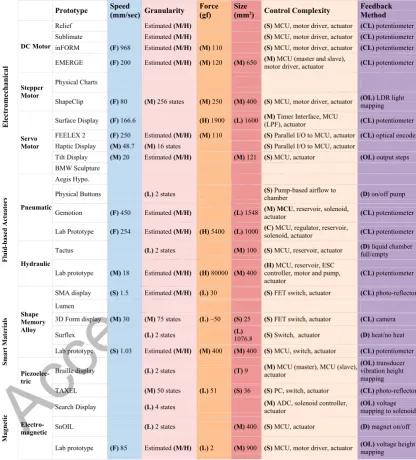
DC Actuator Configuration: We utilized a Bourns motorized linear potentiometer4 (referred to
as a slider) for our setup (Figure 1) similar to the sliders used by inFORM (Follmer et. al., 2013),
EMERGE (Taher et. al., 2015), and Relief (Leithinger et. al., 2011). The T-bar moves vertically
through a mini gear and pulley, which are controlled by the motor shaft. As servomotors use this
same configuration, but measures angular position rather than linear position, and uses gearing
rather than a belt drive, this section is applicable to them as well. The slider is connected to an
3 http://artcom.de/en/project/kinetic-sculpture/ (29/06/2016).
Accepted Manuscript
11
bridge motor driver (see Figure 1) and an ATTiny84 MCU which can accurately control its
position (feedback provided by built-in potentiometer) at ~8MHz using a
proportional-integral-derivative (PID) controller.
DC Actuator Characteristics: This particular slider is capable of 100mm stroke. Larger and
smaller strokes depend on the manufacturer and availability. The sliders are able to support
~130g of force and actuate at ~200mm/s. The size of each slider is 150mm (length) × 50mm
(width) × 13mm (depth) and weighs 75g. Each slider is powered using a 10V supply and can
require up to ~0.8A (i.e. 8W).
Stepper Actuator Configuration: The stepper motor used was similar to those used in DVD
drives. Attached to the motor is a lead screw that vertically moves an attachment (Figure 2). The
stepper motor is controlled by a custom-built PCB that contains an ATmega328p MCU. Vertical
position is controlled using the known number of steps.
Stepper Actuator Characteristics: Each stepper motor is designed to produce a 60mm stroke
using a lead screw. A longer lead screw can be attached to increase stroke length. This would
consume additional power due to longer on-time. The lead screw pitch allows the motor to
support ~250gf and actuate at 80mm/sec. The force and speed is dependent on the density and
pitch of the lead screw, i.e. lower density enables faster actuation, and a lower pitch allows
higher actuation force. Each motor is approximately 20mm (width) × 20mm (depth) × 80mm
(height) whilst closed and weighs 30g.Each stepper motor unit requires up to ~0.54A at 5V (i.e.
Accepted Manuscript
12
3.1.3 Summary and Implications for Shape-Changing Applications
Both DC and stepper motor prototypes, with similar DC motors used in inFORM (Follmer et. al.,
2013) and EMERGE (Taher et. al., 2015), can be stacked closely together as their physical
configuration is relatively minimal. The built-in potentiometer of the DC motor prototype
provides accurate closed-loop position control, thus enabling shape-changing applications to
exploit height resolution (e.g. in data visualization applications where height corresponds to
specific values). In contrast, an open loop method as used in the stepper motor approach allows
for less accurate positioning; however it is possible to use a closed loop approach (e.g. through a
potentiometer). The actuation speed is significantly higher with the DC motor prototype, and can
therefore support higher refresh rates at the user interface level and transition between shapes.
In cases where higher vertical pixel resolution (i.e. bars stacked close together) is desired
the size footprint is still too large at the actuator scale for both approaches and therefore requires
mechanical linkages to reduce pixel spacing on the interface level. In such cases the lead screw
of the stepper prototype is more beneficial as it is able to exert nearly twice as much force to
support the weight and friction of linkages in comparison to this particular DC slider.
A key advantage for belt drives is that the gear/pulley system allows the slider to be
back-driven (e.g. if users want to press an actuating pin/pixel), and allows smoother touch interactions.
A lead-screw can be back-driven, but this depends on the thread pitch (a coarser thread pitch
would be easier to press down) and back-drive is also less smooth. On the other hand, a
gear/pulley belt drive is more susceptible to deterioration from long-term usage as there are more
Accepted Manuscript
13
3.2 Pneumatic Actuation
3.2.1 Background
Pneumatic actuation converts energy using compressed air into mechanical motion. The Aegis
Hyposurface (Goulthorpe et. al., 2001) is a large scale dynamically reconfigurable pneumatic
surface designed as a reactive display and consists of 576 pistons capable of 500mm stroke. The
system uses metallic plates attached to the pistons with projected output. Gemotion (Niiyama and
Kawaguchi, 2008) is a smaller scale pneumatic cylinder/piston based display designed to show
3D shapes using a flexible screen and projection. The system consists of a 7×15 grid of actuators
capable of 150mm stroke at 450mm/sec. Harrison and Hudson (2009) experiment with dynamic
physical buttons using pneumatics; changing between concave, convex, and flat states using
latex layers and visual output from rear projection.
3.2.2 Pneumatic Lab Prototype
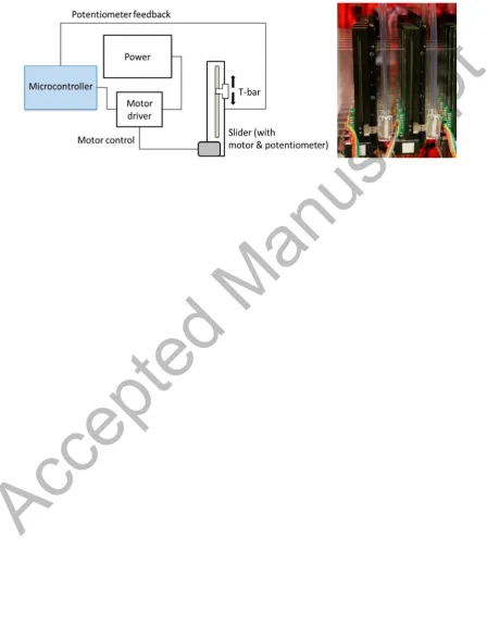
Actuator Configuration: We constructed a pneumatic actuator using a double acting cylinder, a
linear slide potentiometer attached to the cylinders, a solenoid, and an electro-pneumatic pressure
regulator (Figure 3). The components were purchased from VEX Robotics5 (pneumatics kit 2).
We used an Arduino Mega2560 as a controller. The regulator controlled the airflow to the
cylinder through a solenoid by mapping the voltage rating to the flow rate and directing air to the
appropriate valve. These allowed a PWM signal to control the air flow rate. Transistors were
used to drive the 10V pneumatic switch and regulator, requiring an additional power source. We
created a closed loop control system by attaching a linear potentiometer to the cylinder, which
Accepted Manuscript
14
enabled position feedback and PID control. To scale this configuration to multiple cylinders, we
would require careful selection of tube diameter and regulator positioning to ensure sufficient
pressure would be available.
Actuator Characteristics: The cylinder is capable of 50mm stroke. Larger and smaller strokes
depend on the manufacturer and availability. Each cylinder holds a maximum pressure of 100 psi
and produces up to 5.4kg of force at a speed of ~254mm/sec. The reservoir supports 150ml of
compressed air. With the attached components (i.e. potentiometer and linkages) each pneumatic
actuation is 150mm (closed height) × 40mm (width) × 25mm (depth) and weighs 20g. The
regulator is powered by ~26V and ~0.05A (i.e. 1.04W) and requires up to 10V for an input signal
(i.e. the pressure valve opening is proportional to the input signal). The solenoid requires 5V,
0.05A (i.e. 0.4Watts). In total, a single cylinder requires ~ 1.5W. An air compressor would also
be required for continuous air supply, which can consume a high amount of power (up to 100W).
3.2.3 Summary and Implications for Shape-Changing Applications
The pneumatic actuator can exert high force, which can be useful for supporting mechanical
linkages to increase pixel resolution at the interface level, given the actuator size footprint is
relatively large. The actuation speed is high and can therefore support high interface refresh rates
(transitioning between shapes). It supports smooth back-drive, which allows users to smoothly
press and pull the attached pin. However, the physical configuration requires several components
(i.e. solenoids, regulators, switches), which increases the overall size footprint and complexity of
the setup. In addition, the air tubes can suffer from leaks (e.g. if valves are not air-tight).
Whilst the closed loop control is similar to the motorized slider, the PID controller needs
Accepted Manuscript
15
(e.g. if longer tubing is need to reach actuators). This increases the complexity of application
development. Furthermore, position control requires careful consideration as issues such as static
friction and compliance can cause inaccuracies. Gemotion (Niiyama and Kawaguchi, 2008), for
instance, used a friction damper to improve the accuracy of their pneumatic piston.
3.3 Hydraulic Actuation
3.3.1 Background
Hydraulic actuation is built on the principle of manipulating fluid to create mechanical motion.
Tactus is a commercially available technology that can show raised buttons on a touch-screen
display through hydraulic actuation6. The tactile layer is a flat overlay that sits on top of a touch
sensor and deforms into buttons or shapes of specific height, size, and firmness which users can
feel and press down. The tactile layer replaces the passive glass layer of a touchscreen and is
made of thin multi-layer stacks of polymers. The topmost layer is an optically clear elastomer,
beneath which are several micro channels where fluid can flow.
3.3.2 Hydraulic Lab Prototype
Actuator Configuration: Our hydraulic setup (purchased from RC4WD7 starter kit system 1)
consisted of a hydraulic cylinder (Figure 4), a motor and pump, a fluid reservoir (with ISO32
viscosity rating), and an Electronic Speed Controller (ESC). An Arduino UNO was connected to
the pump ESC. To receive position feedback, we attached a linear potentiometer to the cylinder.
Similar to our pneumatic setup described above, this allowed us to use PID control to drive the
Accepted Manuscript
16
cylinder. Unfortunately, our setup was limited to a unidirectional stroke due to part availability;
however bidirectional actuation can be achieved with a double acting pump or through additional
valves.
Actuator Characteristics: The cylinder is capable of a 75mm stroke, which is dependent on the
manufactured unit. The hydraulic cylinder is able to support 80kg (significantly more than other
actuation techniques given its size footprint) and moves at a rate of ~18mm/sec. The cylinder is
20mm in diameter with the potentiometer fitting and 135mm in height (whilst closed). This
configuration requires a 12V, 22A power supply, or 264W for each actuator.
3.3.3 Summary and Implications for Shape-Changing Applications
Using hydraulics for vertical actuation in shape-display applications is relatively uncommon;
Tactus being an example of vertical actuation through a small “bump”. The construction of
hydraulic components can be “messy” due to working with oil-based fluid. Similar to pneumatic
systems, hydraulics can also suffer from leakages, thus the physical setup needs to be robust to
support the high force generated from the piston and pump (the support mechanisms
subsequently increase the footprint).
The actuator can support higher loads (e.g. heavy linkages), however the actuation speed
is very low, which would make transitioning between shapes on the user interface non
user-friendly. This actuator has no option to back-drive, unless specially designed equipment is used.
Therefore, touch interaction is limited. Input power is also exceptionally high compared to other
approaches. Miniaturized actuators that can be stacked in a grid matrix is proposed and discussed
by the Digital Clay concept (Zhu and Book, 2004), including actuator design, feedback methods
Accepted Manuscript
17
the cylinder), and approaches for control architecture (e.g. similar to driving an LED array).
3.4 Smart Materials
3.4.1 Background
Smart materials are capable of altering their properties via external stimuli, such as an electric
current. Shape-Memory Alloys (SMAs) are common materials used in shape-display
applications. Lumen (Poupyrev, Nashida, Maruyama, Rekimoto, and Yamaji, 2004) consists of a
13×13 pixel grid composed of plastic tubes lit with LEDs. Surflex (Coelho, Ishii, and Maes,
2008) uses flexible foam with embedded circuits and SMAs as soft pixels (1076mm2 footprint)
that can deform into different shapes. Nakatani et. al. (2003, 2005) investigated a SMA-based
set-up using a 4×4 pin-rod matrix, which achieves 120mm stroke. The actuators are capable of
exerting 30gf, actuate at 1.5mm/sec and are controlled by an FET switch and photo reflectors for
position feedback. A second prototype was also built as a 16×16 pin matrix using 4mm
(diameter) × 30mm (height) cylindrical rods at 5mm spacing and able to actuate at 1Hz. This
approach used an oil-based cooling mechanism and a camera/marker-recognition method to
provide closed-loop position feedback.
3.4.2 Shape-Memory Alloy Lab Prototype
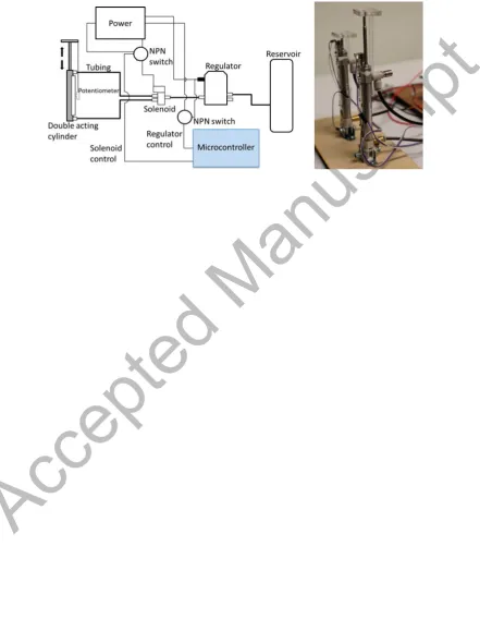
Actuator Configuration: An SMA based actuator was constructed using a Nickel-Titanium
spring (0.75 wire diameter) and a metal extension spring (Figure 5). These were attached on both
ends of a 60mm height linear potentiometer. The compression of the SMA by applying current
and the competitive force from the metal springs enabled vertical movement. The SMA actuator
Accepted Manuscript
18
The slow cooling process of the SMA at room temperature means that the actuator will move
faster in one direction, therefore an active cooling system (e.g. a cooling fan) must be directed
towards the SMA to enable equal bidirectional movement speed. As the position is a function of
the SMA temperature, maintaining a specific level of heat requires careful interplay between
cooling and heating.
Actuator Characteristics: The actuator is only capable of a 6mm stroke, but this is highly
dependent on the properties of the SMA. A thinner coil would allow faster actuation at the
expense of strength, and vice versa. Several variants of metal springs were tried (i.e. different
diameters and lengths). The SMA spring is capable of ~400gf, and can actuate at a rate of
~1.03mm/sec. The dimensions of the actuator are 20mm (width) × 20mm (depth) × 80mm
(height) and weighs 18g. Once the SMA spring is extended using the full force of the metal
extension spring, a total current of 3A is required with 3.3V (i.e. 9.9W), in order to heat up the
SMA through resistive heating such that it returns to its original compressed shape.
3.4.3 Summary and Implications for Shape-Changing Applications
The SMA prototype has low actuation speed, therefore creating a slow refresh rate (e.g. for
transitioning between shapes on the interface level). It also requires additional equipment to
carefully control heating and cooling. For example, Nakatani et. al. (2003, 2005) experimented
with a cooling fan, oil (combined with Peltier effect element), and ethylene glycol. Extension
springs used for applying competitive force are likely to suffer from ‘learning’ the extended
position through multiple extensions by the SMA spring. One approach is to replace the
Accepted Manuscript
19
requires additional cables. The heat required to actuate the SMA spring (up to 50OC) risks
damage to the potentiometer.
This particular SMA prototype has a medium size footprint and can therefore be stacked
closely together. Mechanical linkages can be adequately supported as SMA can exert ~400gf to
increase resolution on the interface. Nakatani et. al’s (2005) 3D form display already consists of
a small footprint of 25mm2 per actuator, therefore creating a high resolution interface. Beneath
the interface level, external cooling and safety mechanisms increases the size and control
complexity. The reliance on temperature also causes difficulties in achieving high accuracy in
position control (Nakatani et. al., 2005), which can be problematic in applications such as data
visualization where height corresponds to values. Power consumption is high for our prototype,
i.e. nearly 10W without cooling, whereas the 3D form displays consumes 3.9W per actuator with
oil-based cooling. In terms of back-drive, rods attached to the SMA prototype can be smoothly
pressed down.
3.5 Electro-magnetic Actuation
3.5.1 Background
In addition to driving electric motors, prototypes have used magnetism to generate motion in
different ways. Prototypes such as SnOil (Frey, 2004) use the magnetic field to manipulate fluid
(i.e. magnetorheological ER fluid, Ferrofluid). Consisting of a grid of 12 ×12 electromagnets
with a basin of Ferrofluid that rests on top, the Ferrofluid reacts to the fields to create
‘bump’-like structures. The electromagnets are powered via multi-layered printed circuit boards.
Frisken-Gibson, Bach-y-Rita, Tompkins, and Webster (1987) constructed a haptic display aimed for
Accepted Manuscript
20 converter and solenoid controller.
3.5.2 Electro-magnetic Lab Prototype
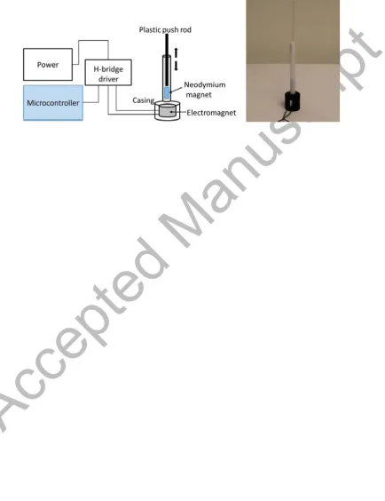
Actuator Configuration: We developed a magnetic actuator by using an electromagnetic coil, a cylindrical neodymium magnet, an H-bridge motor driver, and linkages that allow a push rod to move vertically by pseudo-levitation (Figure 6 ). The electromagnet was encased in a 3D-printed unit and the neodymium magnet housed in a Teflon tube, which allowed low friction movement of a plastic push rod. Positioning was controlled by PWM, which correlates to the strength of the magnetic field repulsion and thus proportional to the height of the repelled magnet. Unlike with a motor, on-time does not equate to the actuation pin moving up or down. This meant that maintaining a specific position required the electromagnet to constantly be switched on, consuming a large amount of power and heating the electromagnet. An H-bridge capable of handling the high voltage and current levels, polarity reversal, and efficient handling of PWM signals was used.
Actuator Characteristics: The stroke length is 17mm. The current setup uses a plastic push rod,
2g in weight as in the pseudo-levitation approach, additional weight reduces the stroke capacity
of the magnet. The speed of movement was ~85mm/sec. Each actuator was ~30mm in diameter
and ~150mm in height, and weighed 70g. Each electromagnet consumes ~30V and ~0.6A (i.e.
18W during peak).
3.5.3 Summary and Implications for Shape-Changing Applications
Heat generation was a prevalent issue with our prototype, which becomes hot after ~30 seconds
of operation at 30V. A cooling system such as a fan and a heat-sink (e.g. a steel baseplate similar
to ForceForm – Tsimeris, Dedman, Broughton, and Gedeon, 2013) is essential for continuous
actuation. Thus, although the physical requirements are relatively minimal, safety measures such
Accepted Manuscript
21
Power consumption is high, and the use of levitation means that the electromagnet must remain
powered to maintain a specific position. Search Display (Frisken-Gibson et. al., 1987) uses
solenoids as linear actuators with four heights; however it is unclear whether heat dissipation
during continuous usage required cooling. Similarly, the electromagnets used in SnOIL (Frey,
2004) need enough charge to create a small “bump” in the Ferrofluid but the input power and
cooling details are not provided.
Once the magnet is repelled in our prototype, the weight it can support decreases
proportional to the square of the distance, thus creating low force output. Therefore, mechanical
linkages in increase interface-level resolution would be impractical. Stacking the actuators also
requires insulation to prevent magnetic interference, which also increases the size footprint.
Back-drive is feasible and any mechanical attachment would also automatically return to its
original position. Height resolution is adequate as the PWM signal is proportional to how far the
mechanical attachment actuates, which also allows accurate control.
3.6 Piezoelectric Actuation
3.6.1 Background
Piezoelectric actuation is typically used for sub-millimeter, high-precision applications. Piezo
expands when an electric current is applied, and typically, piezo actuators have been used for
purposes such as vibration feedback on interactive displays (e.g. Poupyrev et. al., 2002;
Rekimoto and Schwesig, 2006; Chauvelin et al., 2014) or embedded into input devices such as
mice (Kyung, Kwon, and Yang, 2010). The TAXEL system (Kyung et. al., 2011) explores
deformable touch screens with projected visuals by using a thin-film piezoelectric actuator,
Accepted Manuscript
22
reflectors for position feedback. Hernandez et. al. (2009) explore a custom made miniature
piezoelectric linear actuator for braille output (9mm2 footprint), consisting of a piezo-ceramic
disk attached to a shaft and slider, which achieves vertical movement through vibration and
inertia, and controlled using a master and slave MCUs.
3.7 Actuation Techniques Summary
The descriptions and classification (with our taxonomy) of shape-changing displays in past
literature has exposed gaps in actuator descriptions (particularly speed, force and size footprint)
and reflective discussions of their shape-changing applications. The lab prototypes aimed to
provide more detail in terms of actuators. However, shape-display applications are very specific
and can require variable numbers of actuators in various arrangements. The build-process
becomes difficult to predict and classify due to application-specific requirements. To better
understand the challenges faced in specific shape-changing applications and to extend our
characterization beyond the taxonomy, we describe a case study in the next section that details
the implementation of a physically dynamic bar chart. We discuss the challenges faced and
provide guidance for future implementations of similar systems.
4.
Case Study: Shape-changing Bar Chart
Our goal was to develop a physically dynamic bar chart with self-actuating and back-drive
capable bars; integrating a commonly used actuation style and providing a control system at
scale. Users should also be able to physically interact with the bars to perform a range of data
analysis tasks. The hardware requirements included (1) fast, smooth, and accurate actuation, (2)
Accepted Manuscript
23
to comfortably touch and interact with the bars, and (4) can be continuously used over medium
periods of time. Below, we describe the actuation technique according to our taxonomy, the
hardware assembly process, and the control architecture (a full system description can be found
in: Taher et. al., 2015). We decided to use the motorized linear potentiometers as described
above in our explorations of actuation techniques. The properties of the sliders can be classified
using our taxonomy as: Fast actuation speed, Medium/High granularity, Moderate actuation
force, Small size footprint, Moderate control complexity, and PID feedback method.
4.1 Assembly
A 10×10 configuration allowed a manageable size to construct as a first prototype, and also
provided an adequate range for showing bar chart data. The actual bars of the bar chart consisted
of 9.5mm2 plastic push rods. An important challenge was to achieve adequate push rod spacing
for users to interact with. If the push rods were placed directly above the sliders, they would be
>20mm apart, which would hinder user experience. By introducing mechanical linkages (i.e.
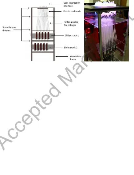
plastic tubing and rod guides) and by arranging the sliders in two levels (Figure 7), we reduced
the spacing to 10mm2. However, the additional weight and friction from the linkages slowed
down the slider actuation speed (which is limited to supporting 130g).
To compensate for additional weight, we overdrove the motors using 12V (exceeding the
10-11V rating). This caused the setup to require up to ~960W when all the sliders are switched
on, which created a large input power footprint. To allow low friction movement in the linkages,
we utilized Teflon tubing (known for their lubricity) to guide flexible fiber-optic rods from the
sliders to the plastic push rods. The mechanical linkages also increased the overall height and
Accepted Manuscript
24
the 100 Teflon tubes and fiber-optic rods in place. A structure of aluminum bars provided rigid
support for the entire setup, which was necessary when all sliders are switched on and generating
large amounts of movement. The vertical distance between the sliders and the push rods had to
be carefully considered, as larger angles to bring the push rods closer together increased friction.
4.2 Visual Output
The visual output of each actuating bar allows users to differentiate between data points, rows,
and columns. We chose to illuminate each bar with an RGB LED, which can be individually
addressed by the control system. The placement of the LEDs required careful planning to avoid
overlapping colours, adequately lighting of each bar, and avoiding additional weight from
linkages. We decided to place 10 LED strips (one strip contains 10 LEDs) on 10 3D printed
column strips that were placed directly underneath the top panel of the system (these also served
as guides for the plastic bars). To enhance the light from the LEDs along the length of the plastic
bars, we experimented with using optical fibre tubes inside the bars, however, this slowed down
actuation from the extra weight. Therefore, we sanded the bars to create a frosted effect, which in
turn adequately distributed the light.
4.3 Control architecture
To enable each slider to be individually addressable, we constructed 17 custom driver boards that
consisted of 3 ATTiny84 MCUs and 6 motor drivers that were able to drive 6 sliders using PID
control. The driver boards were connected by an SPI bus and controlled by 2 Arduino
Mega2650s. One issue that we faced was the electrical noise from closely stacked data cables
Accepted Manuscript
25
various MCUs (i.e. 2 Arduinos and 52 ATTinys) also required careful consideration as it was
important to achieve a high data-bandwidth, i.e. to display sample and refresh rate.
4.4 Reflection
The demands of a physically dynamic bar chart caused unexpected implementation challenges
despite selecting the most suited actuation technique for our shape-changing application; in
particular, applying mechanical linkages whilst maintaining fast actuation and stacking 100
actuators in close proximity. CAD software such as AutoDesk Inventor confirmed the feasibility
of the configuration, but understanding the interaction between different materials (e.g. friction,
robustness) required a trial-and-error approach. For instance, we experimented with various
combinations of push rods and tubing before selecting fiber-optics and Teflon. In addition, we
found that accurately controlling 100 closely stacked actuators requires shielding from electrical
noise.
We chose motorized potentiometers as they included several built-in components, such as
position feedback for accurate closed-loop control, a motor for driving the plastic bars of
EMERGE, and the ability to develop push and pull interactions (enabled by the belt-drive
approach) in our shape-changing application. A key challenge in controlling the sliders was
developing a custom PID controller, which had to be adjusted due to the weight from mechanical
linkages.
The actuators and materials used in constructing EMERGE were fairly robust, as only
three sliders have required replacing (due to detached belts) over a two-year period with regular
usage. The faults were caused by a combination of the strain on the gear and pulley components
from the linkages, the fast actuation speed (i.e. 200mm/sec) from the increased voltage input (to
Accepted Manuscript
26
is useful (e.g. to transition between shapes faster), it is important to slow down actuation speed
where appropriate (e.g. for certain interactions) to reduce the strain on the sliders. As a result, the
maintenance of the various components need careful consideration, i.e. damaged sliders must be
easily accessible. In such cases a more modular approach would be beneficial to minimize time
on disassembling linkages. With regards to user interaction, we found that some users are gentle
whilst pushing and pulling the bars, others can be forceful (which causes strain on the gear and
pulley components).
5.
Discussion
Selecting an actuation technology for developing shape-displays is a matter of balancing desired
features against their side effects; ultimately these choices will depend on the
application-specific requirements. Below we discuss these tradeoffs in the context of requirements
surrounding actuator prototyping, resolution, density, interaction, visual output, and power.
These are supported by guidelines to help researchers select actuation techniques for
shape-changing applications.
5.1 Prototyping Shape-Changing Displays
Electromechanical actuation techniques (e.g. stepper motor, DC motor, servo motor) are better
suited to developing low-fidelity prototypes, i.e. actuators that are functional with coarse grain
control (e.g. the ability to move up and down), and are designed for experimentation. This is due
to the simplicity in configuring a motor to vertically actuate, as well as their high commercial
availability. For instance, a motorized potentiometer (e.g. as used in our prototype investigations
Accepted Manuscript
27
fluids, such as hydraulic and pneumatic, require a learning curve in terms of fluid dynamics and
a more complex set up of reservoirs, tubing, solenoids, and pumps. Electromagnetic and SMA
techniques are simpler than fluid-based techniques as they require a current to activate, however
the vertically moving part needs to be custom built.
High-fidelity prototypes with accurate control that are designed for reliable and
continuous usage can range from electromechanical, hydraulic to pneumatic techniques. In
effect, using pneumatics can actually be more reliable than electromechanical techniques as there
are less moving parts (i.e. using cylinders in fluid systems compared to gears, lead screws and
belt-drives that are more susceptible to wear and tear). Electromagnetic and SMA approaches are
less suited to high-fidelity systems as they are more likely to overheat rapidly and require
sophisticated cooling mechanisms. For example, Nakatani et. al’s SMA prototype (2003, 2005)
included submerging the actuators in an oil based cooling reservoir.
Guideline 1: Electromechanical actuation techniques are best suited for constructing
low-fidelity shape-display prototypes as they are easy to configure and re-configure. While
electromechanical actuators are also suited for high-fidelity prototyping, pneumatic and
hydraulic techniques can be more reliable as they contain less moving parts.
5.2 Shape-Changing Display Resolution and Density
Shape-display resolution (i.e. the number of actuating components that users can interact with)
and density go hand-in-hand, as developing a high resolution display requires a high number of
closely stacked actuators. Actuators that are far apart can hinder user experience, and show an
inadequate level of detail. To achieve higher resolution at the interface level, actuators in
shape-changing displays typically use mechanical linkages to condense the output area. However, these
Accepted Manuscript
28
final power output, especially for electro-mechanical actuators with limited torque. Pneumatic
and hydraulic actuators can better handle linkages due to being able to exert a higher magnitude
of force, however their footprint, and control complexity require larger and more rigid
supporting structures, increasing the overall size of a set-up. SMA actuators can produce a
relatively high actuation force and can be stacked closer together due to their small size.
However, their actuation speed is low and they require highly efficient cooling systems,
increasing the size footprint and the control complexity. Similarly, electromagnetic actuators also
require cooling mechanisms for continuous usage and their stroke capacity is directly affected by
additional weight from linkages. For specialized applications, piezoelectric actuators can be
developed with a miniature footprint.
Interference must also be considered in a dense actuator configuration. It was already
evident in our case study that electrical interference from data cables caused inaccuracies in
potentiometer readings. Similarly, stacking electromagnets can cause magnetic interference.
Cooling systems for SMA actuators can affect surrounding units, and must be targeted towards
individual actuators, which increases control complexity.
Guideline 2: High-resolution shape-changing displays that require mechanical linkages
would benefit from pneumatic and hydraulic techniques due to their ability to mitigate friction
and weight issues caused by the linkages. However, electromechanical approaches are more
practical as they are easier to configure.
5.3 Physically Interactive and Passive Shape-Changing Applications.
Physically interaction shape-changing applications requires the ability to physically move the
actuator up and down as well as receive position feedback to detect the interactions so that a
Accepted Manuscript
29
Pneumatic, electromagnetic, SMA, and electromechanical actuators with a belt drive can be used
to support these interactions (e.g. through a mechanically connected part). Other
electromechanical approaches, such as a lead screw (Hardy et. al., 2015) are more difficult to
manually control. Although our electromagnetic lab prototype (as described in section 3.5.1) was
based on an open-loop approach, using photo-reflectors (e.g. as used by Nakatani et. al., 2003)
can provide closed-loop feedback.
Passive shape-changing applications simply show information and do not require user
interaction (e.g. the Aegis Hyposurface by Goulthorpe et. al., 2001). All actuation techniques are
suited to passive applications, and requirements are determined by specific application
requirements. For instance, if fast transition between shapes is required, approaches such as
pneumatic, electromechanical and electromagnetic are ideal. If the display needs to operate
continuously, then electromagnetic and SMA techniques are less suitable as they have high
heat-output and require sophisticated cooling mechanisms. Finally, if granularity is important (the
number of states an actuator can achieve, thus enabling a display to show more information),
then any of the discussed techniques can, at a minimum, feasibly produce a medium granularity
mechanism.
Guideline 3: Pneumatic, electromagnetic, SMA, and belt driven electromechanical
actuators are ideal for physically interactive shape-changing applications that support
attachments that users can push and pull.
Guideline 4: Passive displays require consideration of application-specific requirements
to determine the suitability of actuators (e.g. electromechanical, pneumatic, and electromagnetic
Accepted Manuscript
30
5.4 Visual Output
Visual output types in existing shape-changing displays typically involve projection (top and
rear), LEDs, digital displays, and no visual output (in such cases the shape-displays serve as
input devices or haptic feedback systems). Many shape-changing displays (e.g. FEELEX – Iwata
et. al., 2001; Niiyama et. al., 2008; TAXEL – Kyung et. al., 2011) use projection on top of the
actuators (usually with a flexible layer). The flexible layer provides a more organic interface for
users, can also integrate sensor technology (Swallow and Thompson, 2001), and the use of
projection enables a wide range graphics, as well as control over the resolution. However,
interacting with a projected interface (e.g. touching the actuators) can occlude the graphics,
especially in top-down projection techniques. EMERGE (Taher et. al., 2015) and LUMEN
(Poupyrev et. al., 2004) utilize LED-based visual output. Displaying graphics on these interfaces
is far more limited, but bars can be wholly illuminated (rather than just the top) without
occlusion. Sublimate (Leithinger et. al., 2013) uses augmented reality, which allows graphics to
be displayed in a 3d space, however this requires additional equipment (e.g. augmented reality
glasses, mobile device). Unlike mechanical actuators, fluid-based systems (pneumatic and
hydraulic) can take advantage of transparent components to provide visual feedback. For
example, fluid actuators can be placed on top of digital graphics displays (e.g. Tactus) to provide
haptic feedback or show deformations (e.g. buttons or landscapes).
The visual output types described above are typically static and separate from the
actuators, but approaches such as using digital displays or flexible displays can be integrated
with the actuator itself. Tilt Displays (Alexander et. al., 2012), for instance, experiments with
tilting a small-scale digital display, and MorePhone (Gomes, Nesbitt, and Vertegaal, 2013) uses
Accepted Manuscript
31
components can enhance the interactivity for shape-displays. For example, a shape-changing bar
chart can have distinctive illuminated bars (through LEDs) with miniature displays that show the
specific value of each bar.
Guideline 5: Visual output techniques such as projection on a flexible sheet placed on
top of the actuators are simpler and allow more visual range. However, integrated visual output
such as LEDs or OLEDs enable better tactile experience with individual actuating components.
5.5 Actuator Power Requirements
Input power requirements are an issue that is seldom discussed in past literature. While research
prototypes are designed to explore application-specific factors, power requirements can
determine the feasibility of using a large number of actuators in a high resolution display in a
real-world scenario. For example, inFORM (Follmer et. al., 2013) consumes 300W for 100
actuators, EMERGE (Taher et. al., 2015) consumes 800W, and our hydraulic prototype
consumes 264W per single unit, making it highly impractical to construct a display with 100
hydraulic actuators. ShapeClip (Hardy et. al., 2015) explores portability through battery powered
units, which can provide power for ~30min. The portability of ShapeClip also allows each
component to be easily removed (e.g. to replace a battery). In this case the battery life is short,
however, exploring more efficient battery technologies is a useful way of reducing the power
footprint and the control complexity.
Guideline 7: Electromechanical actuators typically consume the least amount of power
in comparison to other techniques. However, shape-changing display research remains at an
exploratory stage and investigating interaction and feasibility take precedence over, for instance,
input power. Nevertheless, this creates an opportunity for further research in ways of reducing
Accepted Manuscript
32
5.6 Significance of the Taxonomy
This article has provided in-depth investigations into vertical actuation techniques and their role
in shape-changing display applications through examining past work, constructing and detailing
individual actuator prototypes, and describing a case study with a functional shape-display.
These investigations validate the taxonomy and inform a set of guidelines (as described earlier in
the Discussion section) that aims to aid HCI researchers in selecting actuators for
shape-changing display applications. We therefore contribute original research and build on other
works that have explored broader areas of shape-change. For instance, Rasmussen et. al. (2012)
reviewed the design space of shape-changing displays and their transformative properties,
Roudaut et al. (2013) explored a framework of shape transformations, Coelho and Zigelbaum
(2011) surveyed shape-changing materials and explored soft material prototypes, and Hollerbach
et al. (1992) examined the technical characteristics of various actuation techniques. Our
investigations build on the above work by providing knowledge to HCI researchers about the
technical (e.g. listing and discussing the implications of actuator speed, granularity, force,
footprint, control, and feedback by constructing lab prototypes) and qualitative (e.g. reflecting on
the development and usage of a fully constructed shape-display over a two-year period)
properties of vertical actuators, in the context of shape-changing application development.
5.7 Limitations and Generalization of the Taxonomy
Our characterization was focused on vertical actuation, whereas shape-display research also
includes other dynamic forms such as changes in volume and geometric deformations using soft
materials. The actuators discussed, including the constructed lab prototypes reflects this focus;
Accepted Manuscript
33
is also limited to experiences with one actuation technique and application scenario, whereas
different techniques and applications will create different challenges. Nevertheless, we believe
that our characterization and reflections will allow researchers to better reason about actuator
selection for shape-changing applications.
6.
Conclusion
In this article we have presented a detailed investigation into the various characteristics of
different actuation techniques used for vertical motion in shape-changing displays within the
HCI community which, at present, is limited in exploration. These characteristics have been
broken down and we present them as a taxonomy that is capable of describing the combination
of features we see in the literature. Further, we validate the category breakdown through our own
exploration via small-scale prototypes, through implications of their usage in shape-changing
applications, and by describing a use-case scenario of a fully constructed and functional
shape-changing display. Further, we have discussed that these individual characteristics cannot be
considered in isolation, but instead must be used in parallel with each other when selecting or
creating an actuator design. These are supported by design guidelines to aid researchers in
selecting actuation techniques and to promote the discussion of design requirements and
tradeoffs for developing shape-changing applications. This work provides an original
contribution that builds on previous characterization work in shape-changing displays that has
focused on the general transformative, material, and technical characteristics of shape-change.
As a result, this article aids the rapid development of novel shape-changing interactions by
Accepted Manuscript
34
Acknowledgements
This work forms part of GHOST, a project funded by the European Commission’s 7th
Framework Programme, FET-open scheme (grant #309191).
References
Alexander, J., Lucero, A., and Subramanian, S. (2012). Tilt displays: designing display surfaces
with multi-axis tilting and actuation. Mobile HCI, 161–170.
Chauvelin, C., Sagi, T., Coni, P., André, J. M., Jauze, C., and Lespinet-Najib, V. (2014). Haptics
on a touch screen: characterization of perceptual thresholds. International Journal of
Human-Computer Interaction,30(11), 872-881.
Coelho, M., Ishii, H., and Maes, P. (2008). Surflex: a programmable surface for the design of
tangible interfaces. CHI EA.
Coelho, M., and Maes, P. (2008). Sprout I/O: a texturally rich interface. TEI, 221–222.
Coelho, M., and Zigelbaum, J. (2011). Shape-changing interfaces. Personal and Ubiquitous
Computing, 15, 161–173.
Follmer, S., Leithinger, D., Olwal, A., Hogge, A., and Ishii, H. (2013). inFORM: dynamic
physical affordances and constraints through shape and object actuation. UIST, 417–426.
Frey, M. (2004). SnOil-A Physical Display Based on Ferrofluid.
Frisken-Gibson, S. F., Bach-y-Rita, P., Tompkins, W. J., and Webster, J. G. (1987). A
Accepted Manuscript
35
Gomes, A., Nesbitt, A., and Vertegaal, R. (2013). MorePhone: a study of actuated shape
deformations for flexible thin-film smartphone notifications. CHI, 583-592.
Goulthorpe, M., Burry, M., and Dunlop, G. (2001). Aegis hyposurface: The bordering of
university and practice. of ACADIA, 344–349.
Hardy, J., Weichel, C., Taher, F., Vidler, J., and Alexander, J. (2015) ShapeClip: Towards Rapid
Prototyping with Shape-Changing Displays for Designers. CHI, 19-28.
Harrison, C., and Hudson, S. E. (2009). Providing dynamically changeable physical buttons on a
visual display. CHI, 299–308.
Hernandez, H., Preza, E., and Velazquez, R. (2009). Characterization of a Piezoelectric
Ultrasonic Linear Motor for Braille Displays. CERMA pp.402–407.
Hirota, K., and Hirose, M. (1995). Simulation and presentation of curved surface in virtual
reality environment through surface display. VRAIS, 211–216.
Hollerbach, J.M., Hunter, I.W., and Ballantyne, J. (1992). A comparative analysis of actuator
technologies for robotics. The robotics review, vol. 2, 299-342, August 1992.
Iwata, H., Yano, H., Nakaizumi, F., and Kawamura, R. (2001). Project FEELEX: adding haptic
surface to graphics. SIGGRAPH, 469–476.
Jansen, Y., Karrer, T., and Borchers, J. (2010). MudPad: tactile feedback and haptic texture
Accepted Manuscript
36
Kyung, K. U., Kwon, D. S., and Yang, G. H. (2006). A novel interactive mouse system for
holistic haptic display in a human-computer interface. International Journal of
Human-Computer Interaction, 20(3), 247-270.
Kyung, K., Lim, J. M., Lim, Y., Park, S., Park, S. K., Hwang, I., Choi, S., Seo, J., Kim, S., Yang,
T., and Kwon, D. (2011). TAXEL: Initial progress toward self-morphing visio-haptic interface.
WHC, 37–42.
Leithinger, D., Follmer, S., Olwal, A., Luescher, S., Hogge, A., Lee, J., and Ishii, H. (2013).
Sublimate: State-changing virtual and physical rendering to augment interaction with shape
displays. CHI, 1441–1450.
Leithinger, D., Lakatos, D., Devincenzi, A., Blackshaw, M., and Ishii, H. (2011). Direct and
Gestural Interaction with Relief : A 2 .5D Shape Display. UIST, pp.541–548.
Nakatani, M., Kajimoto, H., Vlack, L., Sekiguchi, D., Kawakami, N., and Tachi, S. (2005).
Control method for a 3D form display with coil-type shape memory alloy. In Proc. ICRA,
1332-1337.
Nakatani, M., Kajimoto, H., and Sekiguchi, D. (2003). 3D Form Display with Shape Memory
Alloy. ICAT, 179–184.
Niiyama, R., and Kawaguchi, Y. (2008). Gemotion Screen: A Generative, Emotional, Interactive
3D Display. In Proc. ASIAGRAPH, 115-120.
Accepted Manuscript
37
Poupyrev, I., Nashida, T., Maruyama, S., Rekimoto, J., and Yamaji, Y. (2004). Lumen:
interactive visual and shape display for calm computing. In ACM SIGGRAPH Emerging
Technologies, 17.
Poupyrev, I., Nashida, T., and Okabe, M. (2007). Actuation and tangible user interfaces: the
Vaucanson duck, robots, and shape displays. TEI, 205–212.
Poupyrev, I., Rekimoto, J., and Maruyama, S. (2002). TouchEngine: a tactile display for
handheld devices. CHI EA, 644–645.
Rasmussen, M., Pedersen, E., Petersen, M., and Hornbæk, K. (2012). Shape-changing interfaces:
a review of the design space and open research questions. CHI, 735–744.
Rekimoto, J., and Schwesig, C. (2006). PreSenseII: bi-directional touch and pressure sensing
interactions with tactile feedback. CHI EA, 1253–1258.
Roudaut, A., Karnik, A., Lochtefield, M., and Subramanian, S. (2013). Morphees: toward high
shape resolution in self-actuated flexible mobile devices. CHI, 593–602.
Swallow, S. S., and Thompson, A. P. (2001). Sensory fabric for ubiquitous
interfaces. International Journal of Human-Computer Interaction, 13(2), 147-159.
Taher, F., Hardy, J., Karnik, A., Weichel, C., Jansen, Y., Hornbaek, K., and Alexander, J. (2015).
Exploring Interactions with Physically Dynamic Bar Charts. CHI, 3237-3246.
Tsimeris, J., Dedman, C., Broughton, M., and Gedeon, T. (2013). ForceForm: A Dynamically
Accepted Manuscript
38
Wagner, C. R., Lederman, S. J., and Howe, R. D. (2002). A tactile shape display using RC
servomotors. HAPTICS, 354–355.
Zhu, H., and Book, W.J. (2004). Practical structure design and control for digital clay. In Proc.