OTHER IMSA
r
PRODUCTS
--8080 MICROCOMPUTER SYSTEM
FLOPPY DISK SYSTEM
DISK OPERATING SYSTE
M
UNE PRINl"ER SYSTEM
MULTIPROCESSOR SYSTE
M
INTE
L
LIGENT BREADBOAR
D
SYSTEM
AP-
44
MINI-PRINTER
H
I
GH
-
LEVEL LANGUAGES
.
8080 SYSTEM SOFTWARE
P
f
R-30 CHARACTER PRIN
T
ER SYSTEM
".. .CRT TERMINAL SYSTEM
COMPLETE LINE OF S-100
C
ARDS
DlliiJ~&D
14860 WICKS BL
V
D.
I
~
CAUTION
FAILURE TO OBSERVE THESE IMPORTANT PRECAUTIONS WILL VOID WARRANTY
1.
2.
3.
4.
5.
6.
7.
8.
9.
10.
11.
12.
13.
14.
15.
16.
17.
18.
Read all material before beginning construction.
Use ON L Y electronic quality rosin core solder.
Use extreme care with static-sensitive chips to prevent static discharge damage. (These chips are inserted in black conductive foam material in your kit.)
Do NOT plug or unplug boards while power is on.
Do NOT apply power to any board or circuit before checking each component and each trace.
Do NOT insert chips in socket before all soldering on the board is completed.
Do NOT use nonstandard parts such as fuses of a higher current rating.
Do NOT leave out any construction step.
Use only specified AC power.
Prevent flat cable end from touching areas of the system that may be carrying current.
Clean unit with soap and water or isopropyl alcohol only to prevent damage to plastic components.
Some repair operations are quite demanding. Do not attempt repairs beyond your level of skill to prevent damage to the board or the components.
Use ON L Y a 25 watt electronic soldering iron for assembly of your IMSAI kit.
Do NOT perform any solder work on a board while power is applied.
Do NOT plug or unplug a chip from a socket while power is applied.
Check power supply voltages BEFORE inserting any boards into chassis.
For all assembled units, read USER GUIDE section for jumpering instructions.
Copyright 1976 IMSAI Manufacturing Corporation 14860 Wicks Boulevard
San Leandro, Ca. 94577 Made in
u.
S. A.IMPORTANT NOTICE
Errata 4/7/77
A Floppy Drive with Floppy Power Supply Rev. 3 is not com-patible with a drive with FPS Rev.' s 0, 1 and 2; 1. e., a dual drive system will not operate with a FPS Rev. 3 and one of the others. FPS Rev. IS 0, 1 and 2 are compatible,
PART 1 SYSTEM MANUAL
FUNCTIONAL DESCRIPTION System Components
SYSTEM THEORY OF OPERATION
Operation of a Simple Floppy Disk System IMSAI Floppy Disk System
SYSTEM CONFIGURATION AND TESTING System Configuration
System Testing
SYSTEM USER ,GUIDE User Controls
System Initialization System Bootstrap
Programming Guide
PART 2 COMPONENTS OF THE SYSTEM
---THE
CONTROLLER---INTERFACE MASTER
Functional Description Theory of Operation Assembly Instructions User Guide
FLOPPY INTERFACE BOARD Functional Description Theory of Operation Assembly Instructions User Guide
FIRMWARE
IMSAI FLOPPY DISK SYSTEM MANUAL
TABLE OF CONTENTS
---THE DRIVE
ASSEMBLY---FLOPPY POWER SUPPLY Functional Description Theory of Operation Assembly Instructions User Guide
FLOPPY LIGHT BOARD Functional Description Theory of Operation Assembly Instructions User Guide
FLOPPY CABINET
Functional Description. Assembly Instructions
APPENDICES---APPENDIX A
reference source to be used in understanding, assembling, and using the IMSAI FLOPPY DISK SYSTEM.
SCOPE ••.•••.•••••••••••. It is assmned that the User is familiar with the operation of the IMSAI 8080 MICROCOMPUTER
SYSTEM. Recommended references:
1. IMSAI 8080 USER MANUAL
2. INTEL 8080 Microcomputer
Systems User Manual
3. Introduction To
Micro-processors - Osborne and Associates
ORGANIZATION •••••••••••• The IMSAI FLOPPY DISK MANUAL is organized into two major sections:
1. THE SYSTEM
2. COMPONENTS OF THE
SYSTEM
THE SYSTEM section covers the operation of the IMSAI FLOPPY DISK as a SYSTEM.
THE COMPONENTS OF THE SYSTEM section covers the operation of the individual components which make up the IMSAI FLOPPY
DISK SYSTEM.
--~~=:-=---=-~
....
-.---*
*
*
i
1
WHAT TO DO WHEN YOU GET YOUR
SYSTEM---If you ordered an assembled FIF and FDC, proceed as follows:
a o. Turn to SYSTEM CONFIGURATION AND TESTING (po 1 - 19) 0
If you ordered and FIF kit and an assembled FDC, proceed as follows:
ao Assemble the IFM as per the IFM ASSEMBLY INSTRUCTIONS (p. 2 - 17).
bo ,Assemble the FIB as per the FIB . ASSEMBLY INSTRUCTIONS (po 3 - 23).
Co Turn to SYSTEM CONFIGURATION AND TESTING (p. 1 - 19).
If you ordered an FIF kit and an Foe kit, proceed as follows:
a. Assemble the IFM as per the IFM ASSEMBLY INSTRUCTIONS (p. 2 - 17) 0
b. Assemble the FIB as per the FIB ASSEMBLY INSTRUCTIONS (p 0 3 - 23).
c. Assemble the FPS as per the FPS ASSEMBLY INSTRUCTIONS (p. 5 - 29).
d. Assemble the FLB as per the FLB ASSEMBLY INSTRUCTIONS (p. 6 - 17).
e~ Assemble the Floppy Cabinet as per
the FLOPPY CABINET ASSEMBLY INSTRUCTIONS (p. 7 - 11).
f. Turn to SYSTEM CONFIGURATION AND TESTING (p. 1 - 19) 0
PART 1
FUNCTIONAL DESCRIPTION
J::".LIUX' X' X .1J..L.!=I.I.'\. ;:n, ;::1".L'J:ij.V,l
Functional Description
The IMSAI Floppy Disk System. provides for control of up to 4 flexible disk drives from the IMSAI 8080 System.
Data formats are fully compatible with the IBM 3740 format, providing a total storage capacity of 1.94 M bits per
flexible di~k. This is organized as
77 tracks with 26 sectors per track.
Each sector contains 128 bytes of data.
To allow for non 3740 compatible formats, provision is made for reading all clock and data bits in an unformatted mode.
The firmware may also be changed by repro-gramming to support varying densities and formats.
The IMSAI Floppy Disk System utilizes an intelligent dedicated controller with a DMA capability to free the main processor from the overhead associated with floppy disk control processing.
Commands to the Floppy Disk System are initiated from the main processor by means of an output instruction to the controller
(Byte Command). The actual command is .
executed from a command string located in
the main system memory. Up to 16 different
command string pointers may c'o-exi'st at any one time, with the values of these command string pointers being User definable.
1 - 4
SYSTEM COMPONENTS
The IMSAI Floppy Disk System consists of a Controller Set and a Drive Assembly.
The Controller Set is composed of two boards, the IFM (Interface Master) and the FIB (Floppy Interface Board).
The IFM is a separate 8080 based processor used to control floppy disk functions. It contains the 8080, 512 bytes of RAM, 2K bytes of EPROM, and all support logic for the 8080 chip. Communications with the ma"in system processor takes place through the DMA channel or the single output port.
The FIB contains all the control logic necessary to drive the floppy disk from the IFM processor.
The Drive Assembly is composed of the Floppy Disk Drive, the Floppy Disk Cabinet, the FPS (Floppy Power Supply), the FLB (Floppy Light Board), and the PLO (data separator).
Each Floppy Cabinet houses up to two complete floppy drives with power supplies and a single FLB. In addition, the cabinet which houses Drive O' contains a single PLO board which may be shared by up to 4 drives.
The Floppy Drive used in the system is the CalComp Model 140 providing up to 3.21 M bits of storage space (1.94 M bits with the IBM 3740 Format). Access times are 6ms track.to track with a 10ms head stabilization.
The FPS provides all power needed to run the floppy disk drives and FLB. Provision is also made to terminate all control and signal lines
from the Floppy Controller Set.
The PLO Board ensures a high level of data integrity and allows for the detection of missing clock patterns as used with the IBM
SYSTEM THEORY OF OPERATION
Copyright 1977 IMSAI Manufacturing Corporation 14860 Wicks Boulevard
THEORY OF OPERATION
PREFACE
This section_is intended to help the User gain a general
understand~ng of how the IMSAI Floppy Disk System functions
as a whole. The operation of a theoretical floppy disk
system is first presented to convey a general understanding
of the principles involved in floppy disk transfers. Once
this is achieved the operation of the IMSAI Floppy Disk System is explained.
Systems Operation does not cover the detailed logic and
timing functions. If this information is desired the User
should reference the Theory of Operations section for the individual system component •.
I. FLOPPY DISK SYSTEMS IN GENERAL
A floppy disk system allows for the storage and retrieval of blocks of data between the main system memory and a storage medium, the
floppy diskette.
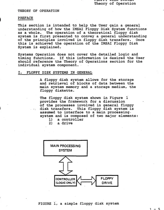
The floppy disk system shown in Figure 1 provides the framework for a discussion of the processes involved in general floppy
disk transfers. This floppy disk system is
assumed to interface to a main processing. system and is composed of two major elements:
l} a controller
2) a drive
MAIN PROCESSING SYSTEM
--FLOPPY DRIVE
FIGURE 1, a simple floppy disk system
[image:15.615.43.599.29.741.2]1 - 6
FLOPPY DISK SYSTEM Theory of Operation
The controller contains all of the logic necessary to interface the floppy disk drive with the main processing system. All transfer routines are taken care of
by the main processor. Note that control
resides with the main processor only.
The drive contains the floppy disk storage unit which utilizes a moveable read/write head to access information stored on a flexible diskette.
DATA FORMATS
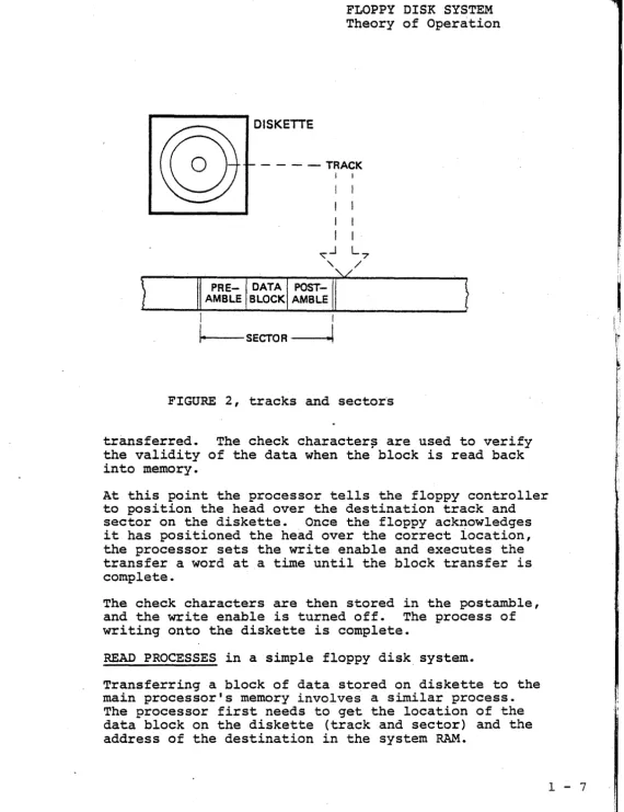
The data on the diskette is organized into tracks and sectors.
A track can be conceived of as a circular ring with its center located at the physical
center of the diskette. If the read/write
head is located a "distance" n from the center of the diskette, the nth track is defined as the area passing directly under the head in one complete1revolution of the diskette.
Each track consists of a number of sectors. A sector is composed of preamble information, a data block, and postamble information.
(See figure 2.)
A preamble information will normally contain:
1) a set pattern to indicate the start of a
sector; 2) the track address; and 3) the sec-tor address.
The data block contains the actual data trans-ferred from the system's main memory.
The postamble information will normally include:
1) a number of check characters and 2) a gap to
fill the end of a sector.
WRITE PROCESSES in a simple floppy disk system.
Assume there exists a block of data located in the sy-stem RAM which is to be stored on a floppy diskette. For simplicity, assume that the block size is equal to
the sector data block size. In order to set up the
transfer, the processor needs to get the address of the data block in system RAM and the location of the
des-tination on the diskette (track and sector). Prior
Theory of Operation
DISKETTE
- - - - T R A C K I
FIGURE 2, tracks and sector's
transferred. The check character~ are used to verify
the validity of the data when the block is read back into memory.
At this point the processor tells the floppy controller to position the head over the destination track and sector on the diskette. Once the floppy acknowledges it has positioned the head over the correct iocation, the processor sets the write enable and executes the transfer a word at a time until the block transfer is complete.
The check characters are then stored in the postamble, and the write enable is turned off. The process of writing onto the diskette is complete.
READ PROCESSES in a simple floppy disk, system.
Transferring a block of data stored on diskette to the main processor's memory involves a similar process.
The processor first needs to get the location of the data block on the diskette (track and sector) and the address of the destination in the system RAM.
,
[image:17.616.42.612.24.764.2]DMA
1 - 8
FLOPPX" lJ.J.::;l\ i:) x ':)".l"J::i.l.Y.I. Theory of Operation
The processor then commands the floppy to position the head over the desired track and sector. When'the floppy acknowledges it has found the requested track and sector, the processor begins reading the data from the diskette into a previously defined storage area until the block read is complete.
The check characters (eRe) are then read and checked
to insure the validity of the data. If the eRe is
correct, the processor transfers the d~ta from the
stor-age area to the desired destination in the system RAM, thus completing the block read process.
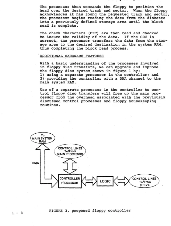
ADDITIONAL HARDWARE FEATURES
With a basic understanding of the processes involved in floppy disc transfers, we can upgrade and improve the floppy disc sys·tem. shown in figure 1 by:
1) using a separate processor in the controller; and 2) providing the controller with a DMA channel to the main system RAM.
Use of a separate processor in the controller to con-trol floppy disc transfers will free up the main pro-cessor from the overhead associated with the previously discussed control processes and floppy housekeeping routines.
CONTROLLER PROCESSOR
[image:18.623.29.591.29.773.2]Introducing a DMA channel into the proposed design of the controller allows for a direct access into
the main system memory. The process of accessing
system RAM then becomes essentially transparent to the main processor.
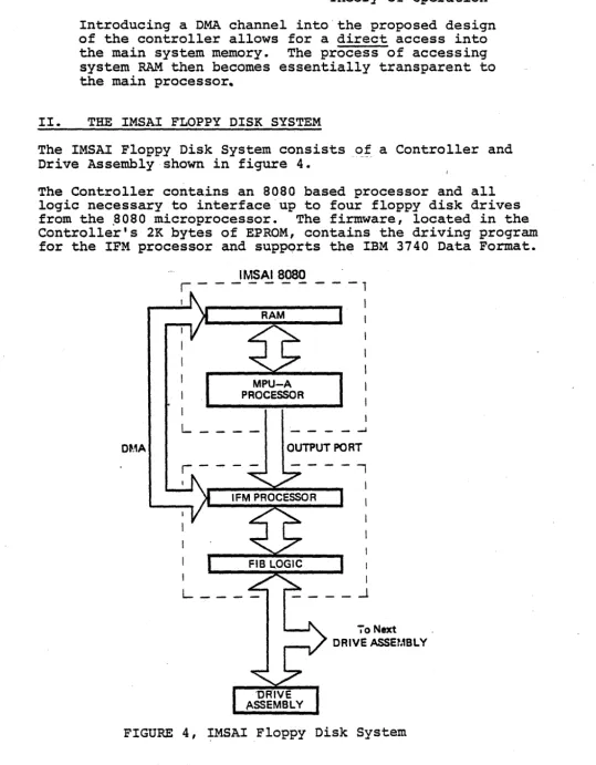
II. THE IMSAI FLOPPY DISK SYSTEM
The IMSAI Floppy Disk System consists of a Controller and Drive Assembly shown in figure 4.
The Controller contains an 8080 based processor and all
logic necessary to interface up to four floppy disk drives
from the .8080 microprocessor. The firmware, located in the
Controller's 2K bytes of EPROM, contains the driving program for the IFM processor and suppQrts the IBM 3740 Data Format.
DMA
IMSAI8080
r - - - -
- - - 1I
MPU-A PROCESSOR
L ___ _
I
_ -J
OUTPUT PORT
--,
70 Next
DRIVE ASSEMBLY
FIGURE 4, IMSAI Floppy Disk System
[image:19.627.55.595.53.745.2]r
1 - 10
IBM 3740 FORMAT.
FLOPPY DISK SYSTEM Theory of Operation
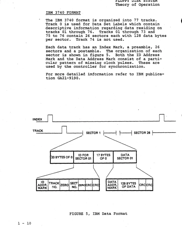
The IBM 3740 format is organized into 77 tracks. Track 0 is used for Data Set Labels which contain descriptive information regarding data residing on
tracks 01 through 76. Tracks 01 through 73 and
75 to 76 contain 26 sectors each with 128 data bytes per sector. Track 74 is not used.
Each data track has an Index Mark, a preamble, 26
sectors and a postamble. The organization of each
sector is shown in figure 5. Both the ID Address
Mark and the Data Address Mark consist of a parti-cular pattern of missing clock pulses. These are used by the controller for synchronization.
For more detailed imformation refer to IBM publica-tion GA21-9190.
INOEX
rl~
______________________________________________
~Il~'
__ _
TR_A_CK _ _ _ _ _
rll-__
-t1
SECTOR11
I ---it
~r---tl
SECTOR 2611---33 BYTES OF 0 SECTOR 10 FOR 01 17 OFO BYTES SECTOR DATA 01
\
)
~
10 TRACK SECT DATA 128 BYTES
AODR. ZERO ER CRe CRC AOOR. CRC CRC
·MARK NO. NO. MARK OF DATA
[image:20.624.16.604.17.750.2]RECORDING FORMAT
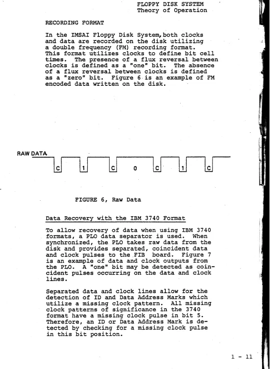
In the IMSAI Floppy Disk System, both clocks and data are recorded on the disk utilizing a double frequency (FM) recording format.
This fo~t utilizes clocks to define bit cell
t~es. The presence of a flux reversal between clocks is defined as a "one" bit. The absence of a flux reversal between clocks is defined as a "zero" bit. Figure 6,is an example of FM encoded data written on the disk.
RAW DATA
o
lJ
FIGURE 6, Raw Data
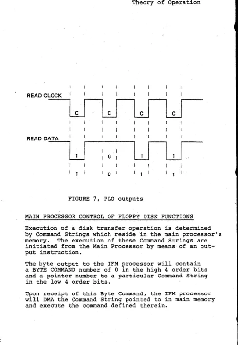
Data Recovery with the IBM 3740 Format
To allow recovery of data when using IBM 3740
formats, a PLO data separator is used. When
synchronized, the PLO takes raw data from the disk and provides separated, coincident data
and clock pulses to the ,FIB board. Figure 7
is an example of data and clock outputs from
the PLO. A "one" bit may be detected as
coin-cident pulses occurring on the data and clock
lines. .
Separated data and clock lines allow for the detection of ID and Data Address Marks which utilize a missing clock pattern. All missing clock patterns of significance in the 3740 format have a missing clock pulse in bit 5. Therefore, an ID or Data Address Mark is de-tected by checking for a missing clock pulse in this bit position.
[image:21.612.64.607.30.769.2]1 - 12
READ CLOCK
READ DATA
LJ
I
1I
01 I 0
FLOPPY DISK SYSTEM Theory of Operation
'I
LJ
I
1I
I
1 1 I,
FIGURE 7, PLO outputs
MAIN PROCESSOR CONTROL OF FLOPPY DI$K FUNCTIONS
Execution of a disk transfer operation is determined by Command Strings which reside in the main processor's
memory. The execution of these Command Strings are
initiated from the Main Processor by means of an out-put instruction.
The byte output to the IFM processor will contain a BYTE COMMAND number of 0 in the high 4 order bits and a pointer number to a particular Command String in the low 4 order bits.
Upon receipt of this Byte Command, the IFM processor will DMA the Command String pointed to in main memory
[image:22.613.79.568.22.732.2]WRITE PROCESSES IN THE IMSAI FLOPPY DI"SK SYSTE~1
MAIN SYSTEM PROCESSES
Assume there exists a block of data located in the main system RAM to be transferred to floppy
·disk. The main processor needs to first set-up
the COMMAND STRING in main memory with 1) the
command number for a sector write; 2) zero in
the Status Byte; 3) ~e destination track ~d
sector number and 4) the address· in memory of
the data block to be transferred.
The main processor then outputs a BYTE
INSTRUC-TION
a
to the IFM output port to initiate theexecution of the write. The acknowledgement of
a completed operation will be indicated by a non-zero value being stored in the status .word of
the COMMAND STRING. Thus once the processor
issues the BYTE COMMAND 0, it only need wait for the status word to go non-zero before proceeding
with another' disk operation. .
CONTROLLER PROCESSES
When the IFM board receives the output instruc-tion (BYTE. COMMAND 0), it lowers the Main
Pro-cessor's READY line. The Main Processor goes into
a WAIT state and the IFM Processor reads the out-put word from the system data bus into its own
accumulator. Once the BYTE COMMAND is read the
IFM Processor raises the System READY line to allow
the SYSTEM to continue. The output word
a
isdecoded by the IFM f~are as being a command to
execute from the COMMAND STRING located in the System RAM.
DMA FUNCTIONS
The IFM processor will present a HOLD REQUEST to the System, and the System will respond with
- HOLD ACXNOWLEDGED. At this point the System is
in a HOLD STATE and the IFM processor will dis-able all of the Main Processor's address, data, and status lines (with the exception of PELDA). The IFM processor then gates its own address, data and status lines onto the System Bus.
The COMMAND STRING is now transferred to the IFM RAM from the System RAM, and the HOLD MQUEST is released, allowing the System to continue with its own processing activity.
r
I1 - 14
FLOPPY DISK SYSTEM Theory of Operation
The Conunand Number is decoded as a Write operation. The IFM processor transfers the Data block to the IFM RAM. This transfer is accomplished by DMA'ing a Byte at a time in the HOLD MODE during state T3
(or the state following T3) of the main processor's machine cycle.
To proceed with the WRITE operation, the IFM proces-sor computes and stores the CRC characters in its own RAM.
TRACK POSITIONING
A request is issued to the FIB to load the head, sync the PLO, and then to synchronize on the ID Address Mark. The FIB then places the IFM Processor in a WAIT State until i t has found the desired missing clock pattern.
Once the FIB has recognized the Address Mark, i t
raises the IFM READY line, allowing the IFM processor to read and check the track address. ·A compare is made to see if the head is positioned over the de-sired track. If not, the direction and Step lines are used to reposition the head over the destination track.
SECTOR POSITIONING
Once again the IFM Processor issues a request to the FIB to synchronize-on the ID Address Mark. The IFM
is again placed in a WAIT State until the ID Address
Mark is recognized. Once the IFM is allowed to con-tinue, i t reads and checks track and sector number, this time looking for the destination sector. If the head is verified to be positioned over the desired sector, the IFM processor waits 12 bytes before
writing the remaining five 0 bytes, the Data Address Mark, 128 bytes of data, and the 2 CRC characters according to the IBM 374.0 Data Format.
COMPLETION OF THE OPERATION
READ PROCESSES IN THE. IMSAI' FLOPPY DISK SYSTEM
MAIN SYSTEM PROCESSES
To prepare for a Read operation the main
pro-cessor sets up the COMMAND WORD in its RAM with:
1) The Command Number for a sector Read;
2} zero in the Status Bvte;
31
the track"and sector number for the datablock"to be read from the diskette;
4} the Address of the destination in Main
. memory.'
The main processor then issues an output in-struction (BYTE COMMAND 0) to initiate the
READ operation. The main processor waits unti~
the Status ~yte of the COMMAND STRING
qoes
non-zero before proceeding with another disk opera-tion.
CONTROLLER PROCESSES
As before, the IFM processor will receive the
output. instruction from the main processo.r and
decode it as an execute from COMMAND ST~G.
The COMMAND STRING wil~ be transferred from the
System RAM to the IFM memory via the DMA access
channel. The Command Number is decoded as a
READ operation and the IFM processor positions the read/write head over the desired track and sector as before. , Once- the head is correctly positioned, the IFM processor waits for the Data Address Mark.
When the Data Address Mark is recognized, 128
bytes of data are read into the IFM RAM. The
two CRC characters are then read and checked to
verify the data block. If the data block is
verified, it is written into the main processor's RAM via the DMA channel.
-To acknowledge completion of the READ operation,
the IEM processor wi~l store a non-zero value
in the Status Byte. This value is then passed to
the COMMAND STRING located in the main system
RAM via the DMA channel.
1 - 15
-t
\
I
i
SYSTEM CONFIGURATION
AND TESTING
Copyright 1977 IMSAI Manufacturing Corporation 14860 Wicks Boulevard
•
•
CONFIGURATION INFORMATION
SINGLE DISK SySTEM---~--- .
FIF-1 CONSISTING OF:
1 IFM 1 FIB 1 CABLE A 1 CABLE C 1 CABLE F
1 CABINET 1 FPS (#O) 1 FLB (#0-1) 1 C140 DRIVE UNIT 1 CABLE E
ORDER:
1 FIF
1 FDC 2-1 (#O)
TWO DISK SySTEM---______ _
FIF-1 AS PER 1 CABINET ORDER:
ABOVE 2 FPS (#0)
(#1) 1 FIF 1 FIF
1 FLB (#0-1) 1 FDC 2-1 ~ 1 FDC 2-2
2 CABLE E 1 Foe
2 C140 DRIVE UNITS (DRIVE O,l)
THREE DISK SySTEM---____ _
FIF-l AS PER ABOVE
CABINET WITH 2 DRIVES AS PER ABOVE AND •..
1 CABINET 1 FPS (#2) 1 FLB (#2-3) 1 C140 DRIVE UNIT 1 CABLE E
1 CABLE C
ORDER:
1 FIF 2 FDC 2-1 1 FDC 1 CABLE C
1 FIF 1 FDC 2-2 OR 1 FDC 2-1
(DRIVE O,l,2)
FOUR DISK
SySTEM---FIF-l AS PER ABOVE
CABINET WITH 2 DRIVES AS PER ABOVE AND .•.
1 CABINET 2 FPS (#2)
(#3) 1 FLB (#2-3)
2 C140 DRIVE UNITS 2 CABLE E
1 CABLE C
ORDER:
1 FIF 1 FIF
2 FDC 2-1 OR 2 FDC 2-2 2 FDC
1 CABLE C
(DRIVE 0,1,2,3)
1 - 19
FLOPPY DISK SYSTEM System Configuration
IMSAI FLOPPY DISK SYSTEM CONFIGURATION
GUIDE---The information here is presented to serve as a reference in configuring an IMSAI Floppy Disk System once its
components have been assembled.
1. SET-THE ADDRESS for the IFM output port by config-uring the header for the address jumper socket in position C3 (IFM). IMSAI standard Floppy address is FD (Hex) ~
a:
::2
16 0 ~
1---1 1 u
2 w
3 i:i:l 4 <J)
5 ~
6 w
8 9 7 a:
o o
~
-2. INSERT THE IFM AND FIB BOARDS into two slots in the IMSAI 8080 Motherboard.
3. IDENTIFY THE THREE CABLES used in the System as follows: CABLE A- CABLE A is a 12" I 25 conductor cable with
an EIA D Type connector on one end and a 26 pin board edge connector on the other end. CABLE C- CABLE C is a 3', 25 conductor cable with
an EIA D Type connector on each end.
NOTE: 3 and 4 Drive systems require 2-Cable C's. CABLE F- CABLE F is a 4", 50 conductor cable with
a 50 pin board edge connector on each end. 4. ATTACH CABLE F between the IFM and FIB Boards. When attaching Cable F, verify that pin 1 on each connec-tor corresponds to pin 1 on the board edge connecconnec-tor. 5. MOUNT THE EIA D TYPE CONNECTOR of Cable A to the
rear of the 8080 chassis with the hardware provided. 6. ATTACH THE REMAINING END OF CABLE A to the FIB Board.
The 26 pin edge connector mates with the edge connector located in the upper left hand corner of-the FIB Board. Verify that pin l o f the connector mates with pin 1 of the board edge connector.
1 - 22
IMSAI FLOPPY DISK SYSTEM CONFIGURATION
GUIDE---SINGLE DRIVE SYSTEM
7. CONNECT CABLE C between the rear of the IMSAI 8080
chassis and the Floppy Drive Chassis as follows. Attach one end of Cable C to the D Type connector of Cable A. The remaining end will connect to the D Type connector located at the rear of the Floppy Chassis BEHIND DRIVE 0, (located 'on the right as you face the front of the Floppy Chassis).
TWO DRIVE SYSTEM
7. CONNECT CABLE C between the rear of the IMSAI 8080
chassis and the Floppy Drive Chassis as follows. Attach one end of Cable C to the D Type connector of Cable A. The remaining end will connect to the D Type connector located at the rear of the Floppy Chassis BEHIND, DRIVE 0, (located on the right as you face the front of the Floppy Chassis).
THREE DRIVE SYSTEM
7. CONNECT ONE CABLE C between the rear of the IMSAI
8080 chassis and the Floppy Drive Chassis as follows: Attach one end of Cable C to the D Type connector of Cable A. The remaining end will connect to the D Type connector located at the 'rear of the Floppy Chassis,
(containing Drives
a
and 1), BEHIND DRIVE 0, (locatedon the right as you face the front of the Floppy Chassis).
CONNECT THE SECOND CABLE C between the two Floppy Drive Chassis' as follows. Attach one end of Cable C to the D Type connector BEHIND DRIVE 1, (located on the left as you face the front of the Floppy Drive
Chassis containing Drives
a
and 1). The remaining endFLOPPY DISK SYSTEM System Configuration
IMSAI FLOPPY DISK SYSTEM CONFIGURATION
GUIDE---FOUR DRIVE SYSTEM
7. CONNECT ONE CABLE C between the rear of the IMSAI 8080 chassis and the second Floppy Drive Chassis as follows. Attach one end of this Cable C to the D Type connector of Cable A. The remaining end will connect to the D Type connector located at the rear of the Floppy Chassis, (containing Drives 0 and 1), BEHIND DRIVE 0, (located on the right as you face the front of the Floppy Drive Chassis).
CONNECT THE SECOND CABLE C between the two Floppy Drive Chassis' as follows. Attach one end of this Cable C to the D Type connector located at the rear of the Floppy Chassis BEHIND DRIVE 2, (located on the right as you face the front of the Floppy Chassis containg Drives 2 and 3). The remaining end will connect to the D Type connector located at the rear of the Floppy Chassis BEHIND DRIVE I, (located on the left as you face the front of the Floppy Chassis containing Drives 0 and 1).
THE IMSAI FLOPPY DISK SYSTEM IS NOW CONFIGURED AS REQUIRED FOR SYSTEM TESTING AND CP/M OPERATION.
I-'
N U1
SINGLE DISK SYSTEM
' \
lMSAI 8050
JrUW.DPm ;SilPJJ
WjR~ldJ
THIS PORTION IS IDENTICAL FOR ALL DISK SYSTEMS. FIF & CABLE C'
8000 PARTS LIST
IFM FIB
iFM-FIB CABLE
CABLE A
CABLE C .. FIF
FLOPPY DISK SYSTEM
CONFIGURATION INFORMATION
II
P.
CJP
\ ' - -
--.,
UNIQUE TO SINGLE DISK SYSTEM SINGLE DISK PARTS LIST
CABINET ,FPS
FLB
Ct40 (DRIVE UNIT)
CABLE E
+ FIF
@Hi76
.---FLOPPY DISK SYSTEM System Testing
SYSTEM
INITIALIZATION---The following procedure should be used when powering up the System.
1. Insure that the diskettes are removed from the Drives.
2. Power up the 8080.
3. Connect the power cord from the Drive Assembly.
4. Insert a diskette in the Drive.
5. The following events should be observed:
a. When the drive becomes Ready, a faint, audible click should be heard as the drive is restored by the Firmware.
b. Status Lights: TRACK 00 should be active;
WRITE ENABLED should be active; HEAD LOADED should be inactive; WRITE should be inactive.
c. Ready and Select:
Both SELECT's should be active. The READY should be active for the drive being used.
IF THESE EVENTS ARE NOT OBSERVED, check the following points:
a. Check all supply voltages on the IFM and FIB Boards.
b. Check and verify all cable connections. c. Check and verify the EPROM located in
position AIO of the IFM Board (PROMOO).
d. Insure that an address jumper has been placed in socket C3 of the IFM Board.
e. Check and verify that the IFM processor is in the RUN state (Al-3).
SYSTEM
TESTING---TEST MODULES
System testing described in this section consists of : 1) testing a single track format operation; 2) testing a sector write; 3) testing a sector read; and 4) testing the head positioning oper-ation.
The test procedure is written so that the User must start with Test Module 1 to test single track
format operations. Each succeeding module may be added to the existing code to test succeeding disk functions.
The complete test procedure requires 512 bytes of RAM beginning at address l8aOH. The Command String resides at address 1880H, and the 128 byte buffer begins at 18aaH.
If an error occurs when running the Test Modules, the Status Word in the Command String should indi-cate the type of error encountered. This in for-. mation may be used to narrow down the possible
sources of trouble given in the following section.
If the Status Word remains a when a failure occurs, the firmware has not completed, or perhaps even started, the operation. Check the DMA control cir-cuits. Reference the IFM Theory of Operations.
TEST MODULE 1
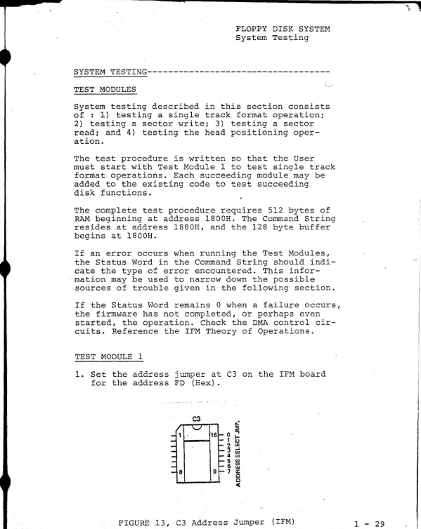
1. Set the address jumper at C3 on the IFM board for the address FD (Hex).
~ ~
~
16 0 ~
1
G
2 w
3 ~ w
4 ~
5 ~
6 w
9, 7 .~ 0 0
<
[image:33.618.13.612.13.767.2]1 - 30
FLOPPY DISK SYSTEM System Testing
2. Load the Test Module 1 beginning at 1889H.
3. RESET
4. EXAMINE 1889H.
5. Set the Drive Select Number in the Programmed
Input Switches as follows:
OlH to select Drive 0 02H to select Drive 1 04H to select Drive 2
08H to select Drive 3
6. Load the Diskette and close the door on the Drive.
-Wait for the Drive to come READY.
7. RUN.
When operating correctly, Track 0 is continuously formatted.
TEST MODULE 2
1. Load the Test Module 2 beginning at 18CDH.
2. Note that Test Module 1 MUST be loaded prior
to using Test Module 2.
3. EXAMINE 1889H.
4. Set the Drive Select Number in the Programmed
Input Switches.
5. Load the Diskette and wait for the Drive to come
READY.
6. RUN.
Test Module 2 will Write from the buffer area at 1800H onto Track 0, Sector 1.
TEST MODULE 3
1. Load Test Module 3 beginning at 18E2H~
2. Test Modules 1 and 2 MUST be loaded prior to using Test Module 3.
4. Set the Drive Select Number in the Programmed Ihput Switches.
5. Load the Diskette and wait for the Drive to
come READY.
6. RUN.
Test Module 3 will Read from Track
a,
Sector 1 intothe Buffer Area at laOOH.
TEST MODULE 4
10 Load Test Module 4 beginning at l8FOHo
2. Test Modules I, 3 and 3 MUST be loaded prior to
using Test Mqdule 4.
~o EXAMINE l889H.
4. Set the Drive Select N~ber in the Programmed
Input Switches.
5. Load the Diskette and wait for the Drive to
come READY.
6. RUN.
Test Module 4 will format Track 76 to test the head positioning routines.
ERROR DEBUGGING
If an error occurs when running Test Module I, the following points should be checked.
GROUP 1
1. Check FIF blue wire modifications (IFM Rev. 2
and 3, FIB Rev. 2 and 3).
2. Check and verify that the diskette is not damaged.
3. Check and verify the firmware in the IFM PROM.
4. Check the OUTPUT COMMAND CONTROL CIRCUIT on the
IFM board. Use the IFM Theory of Operation as
a reference in troubleshooting ..
5. If the Status Word in the Command String remains
--1 ..;. 32
FLOPPY DISK SYSTEM System Testing
o
when the failure occurs, or if the testpro-gram is lost/destroyed when running the test
module, check the DMA CONTROL CIRCUIT. Use the
IFM Theory of Operations as a reference in troubleshooting.
6. Insure that the address jumpers have been
cor-rectly configured in position C3 of the IFM board.
7. Check the LOAD CONTROL CIRCUITS on the FIB
Board. Reference the FIB Theory of Operations.
8. Check the INDEX MARK DETECTION CIRCUIT on the
FIB board. Reference FIB Theory of Operations.
9. Check the IFM RAM CHIPS B9 and B12.
IF AN ERROR OCCURS with the addition of Test Module 2,
check all items listed in GROUP 1 and the following.
GROUP 2
1. Check the SYNCH READ DATA CIRCUIT on the FIB
Board. Reference the FIB Theory of Operations.
2. Check the PLO operation and the PLO SYNCH
circuit on the FIB Board.
IF AN ERROR OCCURS with the addition of Test Module 3,
check all items in GROUPS 1, 2, and the following.
GROUP 3
1. Check the READ DATA CIRCUIT on the FIB.
Reference the FIB Theory of Operations.
2. Check the BYTE DONE CIRCUITS on the FIB.
Reference the FIB Theory of Operations.
IF AN ERROR OCCURS with the addition of Test Module 4,
check all items in GROUPS 1, 2, 3, and the following.
GROUP 4
1. Check the Direction and Step Lines on the FIB
Board. Refer to the CALCOMP OEM Manual for specs.
1 .... ,'1
,
1(".)
,w
o n IN ':'.>l ('{:,0J hj VJ t-J l'xl eJ l'j -.J l::J --..1 1\1 U 0J /\) 1\1 \N (D ().J C) t-J 1 ... .1 (',J tTl (,J t.J (0 CJ
vJ l J 1\.11\) ",1 (\) 0) :.,u eN 0\ '.11 (,1 ~) 01 U f~ e,ll '.1 1\1 (-' /\) -.J t·.". e)l Cd <e:_;P ... 1 :..,. 0J --..1 01 II II lJ,J c.o (j) (JI
CJ ( ' J ().J .... ~
t-..lo I·....l. t·· .... ~~
n.' u. 0) ttl
l.U (,1 h.i lo~J 1\ 1 h.-I h'. J
IS.) c" ""1 t:.J \..i.l " j l:.1
, ... UJ
lJl
l~ I 4;'
1-<
z
hi V) m
"'-,I I-" I n t<} O,l 'x.l bel "<j
C>l U G () I U /\J (),J c" "1J
1-' ,. 4 l····"- I-~ 1-"1-" Leo en OJl)..) t11 llJ
V,
,,,:]
t..l-~
~'.cI
,-j
en CD ".j te) L.j I ... l:) CJ
t ... (-.... , .. ~
lD en CO
Ul ~-, .. -) 1-, uJ
1-3 tf) :s: "1 Ci
t-1 (f) t.,:::{ I'~J ',I (_1 >-l p;.
\,":1 0
<:.., n (fJ ti) (f) (JI 0 1-100 >-lO :,,;: 0:< t-t 0 :~: If) t·; [/J (j) l-' y C> !;:rJ y O t'-f 0 m y t:J l'j 1'-:1 l::'J 1'1 0
:.< :r;.. •.. j ,.~ c.~ I-J ~.u 2.~ (-..:: ;·u >~ CJ 0 C.~1 0 ~ c.::1 ~ tl :;...; ... _:-/ C~: :.>..; ::: c.: j·U (-...I ~.u tJ {.:~ '-I ::-< c.n ,cC) ' .. .) (Il l.) ~u j.'U t t ~ ~).> t·) J ~ t-~ ... J .H ..-:;f .... ...::.:: ... -3 --.~ ... '··3 t--i t-.. t-~ :y tJ. J ... t d t-..::J ;:r:- ~"* r-] tJJ .. u c.~ C1 c:.~·~ ~J
1:-' l'J
b.l ,·-.0 Cl !.j 1/1 :,,; :.'~
"" In U t-~'I
.-; c:: + -to
~ • ' .• 1 r ... ~ (~
rj·· Cl v.. ,~ 1-, I\)
=.~ 1..'::..1 t";LJ 1"":£.1 t';l
l:..J Pi '.lj =-~ ~J..:; r.t ~ 1-1
o
-
...-
...-
...
-.
1-·,1':1 t 1 t.J en '-, ,,~(.J(II "I I." "c'll-j () I 'I C~
r Il ;.!J ~I ~.U C> : . .0 d . - j
L~ 0 U () ;~j
=
'V"j l'.1 ,co. t.-) (~
.···:1 c:n ~", '3 ;.U >-:1
CJ ;.'J 1-3 C.I CJ
-=::: :·I~~ :1'> C"J :-~ 0 ~J
t j C I - : l l-) :.~: ;:: ,.,.\
.... ~ L-~ U 0(1)
Ul :::::
.
I-;lC.) 0
~J..J
~'I
0
~
<,)
() .-, p.- ... -t .J;;. l...:l
.-4
~J;. b .. j t.J:J" h J - .. ~-"'1""t"J.1 :-? ~.q :=-.: c-' 0 =~
...-...
:.1:1 1--1 1-1 :< >--1 r::.~
o <.) u O:l~
...
...
' ...>-l C> ( ) 'i-to :..:::. c.! L: !"I,'''::
r-U.-··.=t .'.1 >-] ·-3
l .... 1-'.1
t-:3 : Jj \""1 C) 1-1 0 :~: (W) t-J t:J :-< ~UO ,:") t,
(n rf) Ul
'-:i ~-.
::..:: ~.p. ;J~" :-0
l') t) U
t:J t.:.J ~
~ .. .u : Jj U
L.::J
~u
('.) n~: '-.1
r.<. ~.i-:
('.: uJ l:J
'1- c~
t-01 ,.oj /\)
~". m W Gi
["I l,rj
I-" (,. hI
\J.i 1-; ~n
r.l.j :2~
~J':'~ lJ,.J
~.r:
... ...
If) .:, .• I>l 1:-..1 (fJ C)
>-.1 Pll·ell'j t~.' W
() "-3 !d ~) 1--3 1-3
:l..1 qo~
1"1 LU I-U t.'J
C~ l U :1.:>- ~ .. {j
'--I bot i-1 C) (J) ~U
;--: h'-II-J (1 ",::1 0
1:'.1
I..'
~!-. ~.u() !::t.1 C)
() ) 0~ ;;...; en
:1:. ... 1-·3 ':) ,:;, ~J;~
l:J b.J IJ
:.0 L~
C) rfl
(n
(J) ::>;., C) 1-' ~l> UJ (,0 '\i>-(;;~ t-> .{J ,. 1-,'"
":::1 :~ hj I-J l'r1 /\) LI)
l-'I . U =< ~.l> U (0 t' J
I cJ + 1-1 ~U ~[j
"J
I-" C> I ] ;J,
...
-._.
"',; (I) (,"1'1 hI Tn 0 1-; l.d i:t.> Irl , .•. ,: .... I"! t-1 C) t cj (:...: H I-J }-::1 t.":.r:-1 ~~tJ ~L:~ ::?: :~ l"'.:I..j
'-'j lJ 0 ~J::,?: hJ
h.J UI .. -3 ::x,.. >-l "1 l-,ej L'" '-3 (') ;.,.> ',;: .... ' ... , ~ .. t: J
(:) \);.. lr .. C) l~ ~ "'1 1 t-..:J 0 ;:d '"~ ,·3 :-:: c) :-0 rJ..-'
(1) c..:~::5: C) l / ) '0 ~~J
I f ) (I) ~J;.o 4' t-e;) OI'J
'-:;J :~~ :1".1 :xJ ~.u
P-~J.':;" r:) ~}..:.~ l - t >--j
,-j ::-s: ;<
t':~ (, ) (ll
-
...
-
...
-.-.-.
,.;;::: t-J (11 (J) 1-:1
t.1 :;d 1-;11·1 t"1
~.lj :'p. ~u 1-3 (/) (f) (' J ,-I til I-.. :J
... ;>~ ~
0 0(':::: :;:
;~ ~ .. .w I·\.! C)
,,~ U
I-" :;''':'1-:1 c:::
L-:I t:l:: l-t
~ 1':1 t'.1 I ... :J
0 0 I-" I-~ ; 0 0
Cl -~~ -5::
~I..-;~ -<
-,J ~ ~r~
U) If) :"''':
r
,
r' \"C
i ( ' \ (., _ _ ~ ' \ J . J 1",,7'\
122.3
=-182C =
12~C =
"t""'l"'~ .,....-...
-.J.. :l \J :..) ,.I..:;.t.l:
1':f'l1=' _.>J ... F51·Z 1= _ ;'1 oJ . . 32·5::-;12·
,I'"
1.3D4
;7
is:;::} Z·25116
leI:2 Z28Z12
13D3 :3':::
leDC ~.""'=L '-~....; _~_....J 1 0::;:
12JF CDSC12
1~'-'"' c~.c C33C18
c
c
c
c'
c
c
c
Civil)ISS ~j3
____ "",T
J:.:.I.)' .1. ;';
if~
~inITI.~ TRAC~ 2
VI~3ION 1.2 1J!~3
ORG·
L'~U
3! ~iU
E~'J :L"J C-:tI S'IA S0~ SIP-. S TJi_ 1\3-S :'}. C.;Ll Ji"'iP 1.3CD2 lS2'3S 132C:C i3iCi 3FI!i lJri Ct'"l~ A G~'O-l-l 8 {\1J.:;+::. Ii C:1J+4: ISC:'\]I
5-:'I"'T _..:r. N
; : N J ~. ~.~ C •
; G? I r~,~ rt 1 TEe [--:i)
; ~. T)f~? C ~/11 ~:J.
;ZZRO Ace
;Z~RO 2T~~U~
; Z~.r\.O 'r? .. ACt~ ;~LCTC3. 1
1""'-'-:: ~.;;:
132J
=
C["lBlese
= ISS LJE18 ~r ~J B~GIN
1'-""'T"'-' -< " / D3FF
18 L4: Fo2'2
~2~E :)2931:3
"'" .l..,:) 1~O ~~ ~7
1':· IA 328112
1 " ?"~,
.l-C":".u G~8G16
1 ::; -:;",
.... -"_...1 'cc33C 12·
3.EADS T?JiC K J
VIRsro~ 1.3 1J/76
ORG-EQU
EqJ
3~U E!
CRr
STA. SUB STA
C >\LL ji'!?
13E2£i 1286E 128GB
133C~
2FFE
2ZE
CMl"
A
C~D+1
I SSUZ
B1>;PI
; G~'r DR.
rw.
;CR,IN ?IAD Ci"1Ii
; STORZ Ci"iL ~~J.
iZERO Ace
; ZERO S T ~u..
'rus
; E {3C C ~1D
c
...•..
,-~. 10 i<'';\ __ v
\, ... ~ . 18SJ
=
CMD133C
=
ISSDE133C
=
3L~IN12 F:3 ;7
18F1 328116
1314 3E~C
19?6 328318
1819 J:3FF
... 13FB ~ 6.3:1
135'J 32:3313
19'1:21 C'D8 C 13
19~3 C'3BG13
I
(
,.)
(
(
("
(
(
l
(
(.
_ . . ~ 1 - 36
TEST i10DULZ 4,
FORt'-lATS T1AC ~ 76
V~dEIO~ 1.0 12/76
ORG 13F02:
~>~u 18.·S0.E
3QU l:'""'o"TT =~I.t!1
EqU 133CH
SU3 A ;ZIRO
STA C~1D+1
,
ZE:iO:WI A,4-cH jTRACz.:
srA
CMD+3;STca;
AGe
Sl'ATD"S 76
rn._~C
:(
I ~! CSI~ ~FFE ; ~j:£ T D?IVI NO.
o
itI 3Jii,
'J':": T ,.-
:~ ;OR:-'~T ~lO •S -r.l.
c
~"'D ; 2TORE ChD"
• 'Ii " \J •CALL 15SUZ ;3:IEC GrviD STi
AND
NOW---Once your system has passed the system Testing previously described, you may proceed in one of
several ways.
*
*
*
If you wish to bring up IMSAI, CP/M, refer to the IMSAI CP/M USER MANUAL for further instructions.
If you wish to write your own disk access programs, refer to the Prog-ramming Guide in the System User Guide section of this manual. In
writing your own disk access programs, i t is adviseable to read the system Theory of Operation to gain a general understanding of the system operation.
If you wish to understand the operation of the system, the following sections of this manual may prove helpful.
f system Theory of Operation
.. IFM Theory of Operation FIB Theory of operation
FIB Firmware Theory of Operation Cal Comp OEM Reference Manual for the Model 140 Drive.
SYSTEM USER GUIDE
Copyright 1977 IMSAI Manufacturing Corporation 14860 Wicks Boulevard
CAUTION
Take Diskettes out of the drives during system power up or down to prevent any possible changing of data.
FLOPPY DISK SYSTEM User Guide
USER
GUIDE---~---USER CONTROLS
POWER SWITCH: The AC power switch is located at
the rear of each FPS. Assembled Drives are shipped with this switch in the power-on position.
LOADING AND REMOVING DISKETTES: In the center of
the face of each Drive is a simple, thumb operated pushbutton which is depressed to allow the spring-loaded front cover to open. The Flexible Disk may then be inserted or removed as appropriate. The cover may then be closed manually.
NOTE: Remove the Diskette from the drive before
power is applied to or removed from the Controller Boards.
LIGHT DISPLAY: The Light Display monitors the
READY and SELECT Lines for each Drive in the cab-inet. The states of the four signal lines TRACKOO, HEAD LD, WRITE, and WRITE ENABLED are monitored for the selected Drive.
SELECT: A SELECT line will become active when the
Controller raises the Select Line for the appro-priate Drive. Both Select Lines will appear to be continuously active since the Controller uses these lines in a polling process to determine if a Drive has become Ready.
READY: This will become active when a diskette
is loaded and the cover is closed on a selected Drive.
TRACK 00: The TRACK 00 line will become active
when the Read/Write head on the selected drive is positioned over Track 00.
1 - 44
HEAD LOAD: The HEAD LOAD line will become active
when the Controller issues a request to the selected Drive to load the Read/Write head. WRITE: The WRITE line will become active when
the Controller issues a command to the selected
drive to enable the Write line.
WRITE ENABLED: The WRITE ENABLED line will be-come active when the selected Drive acknowledges that the loaded diskette is not write protected.
Circuitry in the Drive to support this feature is not standard.
SYSTEM INITIALIZATION
The following procedure should be used when power-ing up the System.
1. Insure that the diskettes are removed from the Drives.
2. Power up the 8080.
3. Connect the power cord from the Drive Assembly. 4. Insert a diskette in the Drive.
5. The following events should be observed:
a. When the Drive becomes Ready, a faint,
aud-ible click should be heard as the drive is
restored by the Firmware.
b. Status Lights: TRACK 00 should be active;
WRITE ENABLED should be active;
HEAD LOADED should be inactive; WRITE should be inactive.
FLOPPY DISK SYSTEM User Guide
SYSTEM BOOTSTRAP (IFM REV 3 FIRMWARE ONLY)
A IIbootstrap" is a short program which reads another pro-gram from some storage medium into system RAM and executes it. This simple, yet general procedure gives the user "freedom to load in any kind of operating system slhe
de-sires." The IMSAI Floppy Disk System bootstrap reads sec-tor 1 of track ~ from drive ~ into system RAM at ~-7F and then jumps to location ~.
The following procedure should be used when bootstrapping from an IMSAI CP/M System Diskette.
1. Insure that the diskettes are removed from the drives.
2. Power up the 8080.
3. Power up the floppy disk drive.
4. Insert a system diskette in drive ~.
5. When the drive becomes READY, press RESET.
6. Set the ADDRESS switches for ~~~~ and press EXA..N1INE. A "C3" shculd appear in the DATA lights.
7. Press RUN.
At this point, the operating system should be loaded and run.
If a hardware error occur's, the error code (see FIB Soft-ware section) will be displayed in the PROGRAMMED OUTPUT lights. The bootstrap will be retried until i t is success-ful, or until i t is stopped. If unable to bootstrap, check the points described at the end of the SYSTEM INITIALIZATION section.
1 - 46
E
PROGRAMMING GUIDE
A. Introduction
An Assembly Language Program stored in the 8080 System Memory is necessary to access the Floppy Disk. To use the IMSAI Floppy Disk
System, the User must understand how to write such a program.
In order to accomplish this, the User may think of the Floppy Disk as a SINGLE OUTPUT PORT from the 8080 Microprocessor System.
The program which will access the Floppy Disk System utilizes TWO TYPES OF INSTRUCTIONS:
1. BYTE INSTRUCTIONS and
2. A COMMAND STRING INSTRUCTION.
BYTE INSTRUCTIONS are OUTPUT INSTRUCTIONS to the output port of the Floppy Disk System. A COMMAND STRING is a series of consecutive words located in the System Memory.
The processes which need to take place within this program are described as follows.
START ••••• SET UP THE COMMAND STRING IN p~
FOR A PARTICULAR DISK OPERATION
END •••••••
- - --~
ISSUE THE BYTE COMMAND (OUTPUT INSTRUC-TION). TO INITIATE THE EXECUTION OF A DISK OPERATION
CHECK THE STATUS WORD IN THE COMMAND STRING FOR AN INDICATION THAT THE DISK OPERATION IS COMPLETE
The sections of the USER GUIDE which follow give the detailed information necessary to WRITE THE .FLOPPY DISK ACCESS PROGRAM.
FLOPPY DISK SYSTEM User Guide
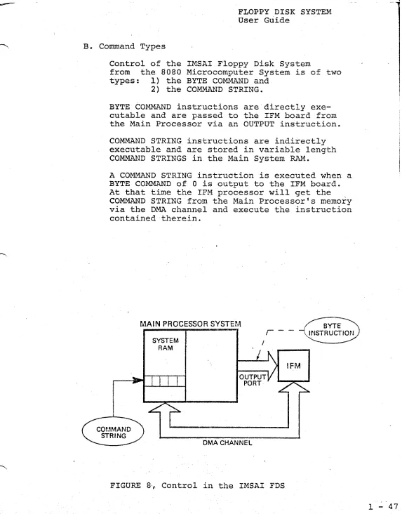
B. Command Types
Control of the IMSAI Floppy Disk System
from the 8080 Microcomputer System is of two types: 1) the BYTE COMMAND and
2) the COMMAND STRING.
BYTE COMMAND instructions are directly exe-cutable and are passed to the IFM board from the Main Processor via an OUTPUT instruction.
COMMAND STRING instructions are indirectly executable and are stored in variable length COMMAND STRINGS in the Main System RAM.
A COMMAND STRING instruction is executed when a BYTE COMMAND of
a
is output to the IFM board. At that time the IFM processor will get the COMMAND STRING from the Main Processor's memory via the DMA channel and execute the instruction contained therein.MAIN PROCESSOR SYSTEM
SYSTEM RAM
,-OUTPUT PORT
DMA CHANNEL
FIGURE 8, Control in the IMSAI FDS
BYTE
\.INSTRUCTION
[image:48.612.34.607.23.755.2]r
1 - 48
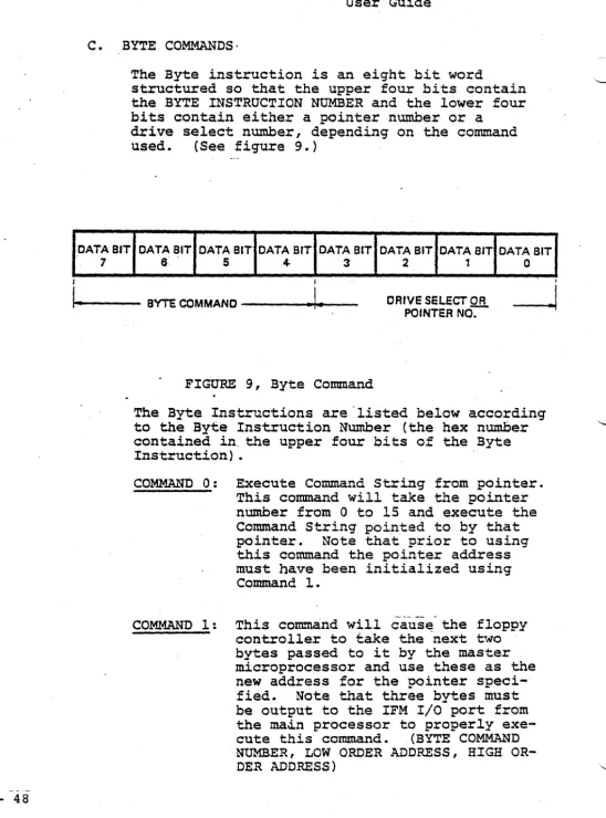
C. BYTE COMMANDS·
DATA BIT
7
The Byte instruction is an eight bit word
structured so that the upper four bits contain the BYTE INSTRUCTION NUMBER and the lower four bits contain either a painter number or a
drive select number, depending on the command
used. (See figure 9.)
DATA BIT DATA BIT DATA BIT DATA BIT DATA BIT DATA BIT DATA BIT
6 5 4- 3 2 1 0
I I I
It-o-.----
BYTE COMMANO----~I
... --
DRIVE SELECT ORPOINTER NO-:-
----J
FIGURE 9, Byte Command
The Byte Instructions are "listed below according to the Byte Instruction Number (the hex number contained in" the upper four bits of the Byte Instruction) •
COMMAND 0: Execute Command String from pointer.
This command will take the pointer number from 0 to 15 and execute the Command String pointed to by that
pointer. Note that prior to using
this command the pointer address must have been initialized using Command 1.
COMMAND 1: This command will cause the floppy
controller to take the -next two bytes passed to it by the master microprocessor and use these as the new address for the pointer
speci-fied. Note that three bytes must
be output to the IFM I/O port from the ma~n processor to properly
exe-cute this command. (BYTE COMMAND
[image:49.634.46.594.24.764.2]FLOPPY DISK SYST~~ User G.uide
COMMAND 2: Restore Drive causes the floppy con-troller to execute a restore command
(position the head over track 0) on any or all drives selected.
CO~~D 3: Set Software Write Protect causes the controller to set a Write Protect on any of the drives which are selected. Note that in a power on condition, all drives come up WRITE ENABLED and therefore the WRITE PROTECT must be reset whenever power goes on.
COMMAND 4: Software WRITE ENABLE causes the mi-croprocessor or the floppy controller to remove the WRITE PROTECT on any or all drives selected.
COMMAND 5 through COMMAND 15 perform no operation, except to reset interrupt if interrupt
mode is being used. IMSAI standard
RESET INTERRUPT command is command 5.
POINTERS
The pointer is a number from 0 to 15 which signi-fies that one of 16 addresses be. used as the address
9f the Command String in Main Memory. Byte Commands
o
and 1 will take the lower four bits of the ByteInstruction Word as a pointer number to a Command
String address. Note that Byte Command 1 is used
to initialize the addresses of the pointers, while Byte Command 0 will execute the Command String pointed to by the lower four bits of the Byte
Com-mand ~qord. .
On system power-up or RESET, the sixteen pointers are initialized with the following default values
(all in hexadeci.rnal).
;3: ;3;38~ 4: 4;3;3~ 8 : 8;3~~' C: C~~Xf
1: 1~~;3 5: 5~;3~ 9 : 9~~~ D: D~f1f1
2 : 2~~~ 6: 6~~f1 A: A~~f1 E: E~~f1 3: 3~~~ 7: 7;3~~ B: B~~~ F: F~~~
DRIVE SELECT NUMBERS
Byte Commands 2, 3 and 4 will take the lower four bits of the Byte Instruction Word as a Drive Select
number. A dri:ve is selected (O-3) if its
corres-ponding bit is a 1. A command with no drives
se-lected does no operation.
' I
I
I
I.
1 - 50
COMMANDS 2, 3 or 4
I
DRIVE SELECT NUMBER
SELECT SELECT SELECT SELECT DRIVE 3 DRIVE 2 DRIVE 1 DRIVE
a
BIT3 BIT 2 BIT 1 . BIT
a
I [image:51.638.38.597.18.764.2]BYTE COMMAND
---~.I
FIGURE ~O, Drive Select Numbers
D. COMMAND STRING INSTRUCTIONS
Command String Instructions are indirectly executable and are stored in a variable length Command String in the Main System RAM.
The Command String is a series of from 4 to 9 consecutive 8 bit bytes in the main processor's
memory. Its length or structure is dependant
on the command used.
SYSTEM RAM
~I""--- REQUIRED
---1-,
WORD
1
t
:WORD 21 WORD 3 1 WORD41
WORD51 .. ·
·1
WORD9j
I I
~ QPTIONAL
-..1
AS REQUIREDIt
I
!
•
FLOPPY DISK SYSTEM User Guide
All Command Strings consist of at least four bytes of information. The definition of each 8 bit byte in the Command String is given below.
BYTE I - Command Byte
This byte contains a command number in the upper hexadecimal digit and the drive select number in the lower digit. The operation for each Command Number is defined in the next section and a drive is selected (0-3) if its corresponding bit is a one (bits 0-3).
BYTE 2 - Status Byte
This byte indicates to the master microprocessor the status of the present disk operation. It must be SET EQUAL TO 0 prior to executing the
single Byte Command
o.
This byte is set non-zero at the completion of the Command String by the IFM processor. If bit 7 is set, i t indicates that the operation was not completed successfully~ Bito
only is set on successful completion. BYTE 3 and 4 --Track AddressTwo Bytes are allowed for the track-address for future expansion. At this time, Byte 3 must be 0, and Byte 4 contains a value from 0 - 76 to specify on what- track the operation should be performed. Note that to maintain IBM medi.a com-patibility, i t is possible to have the logical and Rhysical track address differ. For commands to process this type of data, Bytes 3 - 4 contain the physical track address number.
Care mus_t be exercised in operating with the logical and physical track address being differ-ent, and the user must be totally familiar with the format slhe is working with to perform any operation of this nature. For commands which spe-cify no further track address, these two bytes contain both the physical and logical track ad-dress numbers.
BYTE 5 to 9
I - 5 2
COMMAND TYPES
The individual Command String commands are listed below by the command numbers - the upper four bits of the Command Byte.
COMMAND 0
The READ ALL command causes the IFM to delay the number of milliseconds contained in Byte position 5 from the physical index poles of the floppy disk
and then to read 64 bytes. For each data byte,
the corresponding clock byte is also read and is s-tored in the next_ sequential location in memory
(i.e., stored are data from byte 1, clock from
byte 1, data from byte 2, clock from byte 2, etc.). Hence, 128 bytes are transferred to the main pro-cessors memory at the data buffer location pointed
to in Bytes' 6 and 7. The delay in Byte 5 can be
from 0 to 255 ms.
Note that the 64 bytes on the floppy disks consume' approximately 2 ms and that software recognition fo;r repositioning of the data is required to com-pletely reconstruct the data pattern which is on the floppy disk. This command shoulg be used with caution, and the user should be totally familiar
with format contained on the floppy disk slhe is
referencing before attempting to use the command. It is normal.ly used only' in cases of extreme dif-ficulty or to decipher an unknown diskette format.
COMMAND 1
The WRITE SECTOR command causes the floppy con-troller to write the data from the location pointed
to by Bytes 6 and 7. Byte 6 contains the least
significant half of the data buffer location, and
Byte 7 contains the most significant half. The
data is written in the sector specified in Byte 5 (from 1 to 26).
COMMAND 2
READ SECTOR: The sector number contained in Byte
5 (from
1
to 26) is read and, upon successfulcom-pletion of the read, the data is transferred to
the data buffer location contained in Bytes 6 and
7. Byte 6 contains the least significant half of
the data buffer location, and Byte 7 contains the the most significant half.