doi:10.4236/ijcns.2010.310112 Published Online October 2010 (http://www.SciRP.org/journal/ijcns)
A Turbo Decoder Included in a Multi-User Detector:
A Solution to be Retained
Sylvie Kerouédan1,2, Makram Touzri1, Patrick Adde1,2, Samir Saoudi1,2
1
Institut Télécom, Télécom Bretagne, UMR CNRS 3192 Lab-STICC, Brest, France
2
Université Européenne de Bretagne (UEB), France
E-mail: [email protected], [email protected], [email protected],
Received July 13, 2010; revised August 18, 2010; accepted September 20, 2010
Abstract
This paper deals with the presentation of different multi-user detectors in the Universal Mobile Telecommunica-tions System (UMTS) context. The challenge is always to optimize the compromise between performance and complexity. Compared with the solution commonly used today, the rake detector, successive interference cancel-lation (SIC) detector has better performance despite its higher complexity. Our innovative solution proposes join-ing detector and channel turbo decoder to get a significant gain in terms of performance. Furthermore, when de-tection and decoding are implemented in a single function, complexity does not increase much.
Keywords:CDMA, Turbocode, Multi-User Detection, Turbo-CDMA
1. Introduction
There is today a high demand for increasing the number of users in wireless communication systems, and sharing techniques have been implemented. When many users have to share the same spectrum resource, multi-user detection (MUD) algorithms have to be implemented in the receiver. Well-known MUD techniques use time, frequency or code division to share resources between users. In our study we focus on one technique: code divi- sion multiple access (CDMA). Figure 1 summarizes the principle of spread spectrum and code division in a CDMA system in order to give some key notations use- ful for reading the paper.
On the other hand, outstanding channel coding algo- rithms, such as turbo techniques, can reach very high data rates, or can offer the possibility of low power emission. Joining a MUD receiver and a turbo decoder in an iterative process has been seen as a good way to merge the advantages of the two techniques. This asso- ciation can be done in different ways:
separately, which means doing first a few stages of SIC-receiver (Successive Interference Can- cellation) and then several iterations of a turbo decoder (SIC-turbo configuration),
jointly, which means that the turbo decoder is
an inner part of the SIC unit (turbo-SIC con- figuration).
The second proposal is very interesting in terms of per-formance but seems to be very complex due to the pres-ence of a turbo decoder in the core of the SIC cell. At pre-sent time, in the universal mobile telecommunications system uplink context, the solution generally retained in the base station is the classical rake detection followed by a bank of channel decoders. The goal of our study is to show that the detector and turbo decoder association can be competitive against the simplicity of the classical solu-tion. We compare different architectures: the classical rake receiver (CONFIG 1) [1], the SIC-turbo receiver (CON-FIG 2) and the turbo-SIC receiver (CON(CON-FIG 3) [2]. The three architectures have been described in C language to get performance curves, and then in VHDL to be synthe-sized with Synopsys Design Analyzer on ST 90 nm target technology to get complexity data. This study and the re-sults have been widely described and justified in [3].
The paper is organized as follows: in Section 2 we de- scribe the implementation of a successive interference cancellation detector; in Section 3, the different associa- tions of channel decoding and multi-user detector are explained; and the last section is dedicated to the com- parisons of the different architectures.
827
f Noise or Scrambler
spread spectrum 1
Ts
f
original spectrum
f 1
Tc =SF× 1 Ts 1 symbolSF chips
SF=Spreading Factor
Tc Ts
t -{Code ck}+{Code ck}
Code ck t
Spread sequence
Ts
t
× data
+
Noise data
Code ck
× Code c1
Code ck
× +
. . .
Transmitter Channel Receiver
f (user 1)
(userk)
[image:2.595.87.511.88.307.2]for the kth user
Figure 1. Principle of spread spectrum and code division in CDMA system.
2. Successive Interference Cancellation
Detection
2.1. Generalities
In a multi-user context, the goal of interference cancella- tion is to eliminate interference due to the current user by estimating the transmitted signal and then subtracting it from the received signal. The successive interference cancellation (SIC) detector is based on serial processing of the estimation and the interference cancellation. The SIC detector is a good compromise between performance and complexity compared with parallel or hybrid inter- ference cancellation detectors [4].
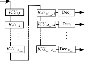
SIC structure, shown in Figure 2, is composed of M
steps of K interference cancellation units (ICU), where K
is the total number of users. Inside each ICU, we can find as demonstrated in Figure 3:
ICU1,1
ICU1,2
ICU1, Kmax
. .
.
. . .
Dec1
DecKmax
Dec2
ICUMmax, 1
ICUMmax, 2
Mmax, Kmax
ICU
. . .
Figure 2. Classical structure of a SIC detector.
+ ×
+
×
interference cancellation matched
filter local emitter
k m y 1,
1 ,k m e
k m e ,
k m y ,
k s T
k s
-Figure 3. Synoptic of the internal structure of an ICU in the case of a transmission over a Gaussian channel.
a matched filter linked to the current user k, a local emitter to regenerate the interference due
to the current user,
an operator which computes the residual signal
em,kafter current interference cancellation.
This residual signal is then sent to the following ICUm,k+1. The internal structure of an ICU can be more or less complex depending on whether channel decoding is implemented inside or not.
2.2. Implementation of an ICU
In this section, we describe the implementation of the different blocks of the ICUm,k as shown in Figure 2. First
[image:2.595.318.532.344.490.2] [image:2.595.89.256.585.704.2](period Ts) (cf. Figure 1).
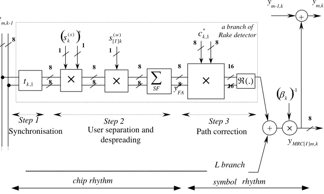
[image:3.595.134.464.507.705.2]2.2.1. Matched Filter Block
Figure 4 shows the architecture of the matched filter. The inputs of this block for the current user k (k = 1, 2, …, K) at the step m (m = 1, 2, …, M) are
the residual signal em,k-1 from previous k-1 user,
the k user code (scrambling sk( )S and spreading
) (
] [
w k I
s codes for data link),
the estimated channel coefficients ck l, ,
the delays tk l, coming from the L channel paths.
The output of this block is the residual estimation of the received symbol. For each branch the input sequence of SF chips is multiplied by the conjugate of the scram- bling code to select the current user k. The resulting se- quence is then despread (step 2). A multiplication by the channel coefficients corrects the effect of the multiple paths (step 3). The result is then normalized.
The implementation of the block can focus either on delay (combinational architecture) or on surface (sequen-tial architecture). The match filter complexity depends on the number L of multiple paths performed during the computation:
the larger the L, the higher the number of gates if L branches are implemented;
the larger the L, the slower the circuit if only one branch is implemented.
For our implementation, we choose to use only one branch.
2.2.2. Local Emitter Block
This block delivers a sequence image of the interference of the current user k which is part of the residual signal at the input of ICU k. Among several architectures, we
choose to implement a combinational function. In this solution, described in Figure 5, a parallel process sends
SFk (spreading factor of user k) chips to the interference
cancellation block in order to take into account the mul-tiple paths.
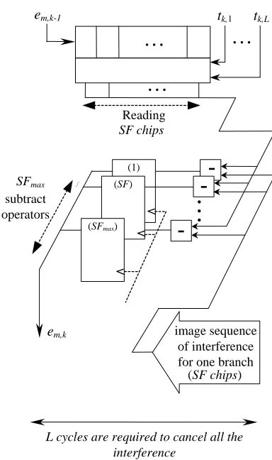
2.2.3. Interference Cancellation Block
This block receives the residual signal coming from the previous user k-1 and the image of the interference gen-erated by the local emitter in order to compute the resid-ual signal of the current user k. As described in Figure 6, SFmax operators of subtraction are implemented to com-pute interference cancellation during L clock cycles. Thanks to the combinational structure, this block is not very complex.
2.2.4. Time Analysis of the ICU
Depending on architecture choices, the time required to compute a data symbol can be different. In Figure 7 we give the processing delays if we choose to implement sequential or combinational operators. In the analysis we consider L = 6 paths and a sliding window [5] of size 5. Thanks to the sliding window, we can recover the estimation of previously processed symbols to re-duce the latency of the process. Thus the required number of clock cycles is 306 to process the interference cancellation.
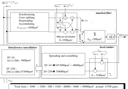
2.2.5. Complexity of the Logic Glue in the ICU
To evaluate the complexity, we describe the ICU in VHDL and then synthesize the design with Synopsys Design Analyzer. The target technology is ST microelec- tronics 90 nm. In Table 1, we give common parameters.
Figure 8 shows the area of the different part of the
×
×
×
1 ,
k
t
+
1
(.)
× 1
1
8 8
8 8
8 8
8 8
8
8 8
8 16
16
8
e m,k-1
k m I MRC y [] ,
(s)*k
s ( )
] [
w k I
s
* 1 ,
k
c
Step 1 Step 2 Step 3
Synchronisation Path correction
L branch
chip rhythm symbol rhythm
a branch of Rake detector
1k
y FA
+
y m,k y
m-1,k
SF
User separation and despreading
829
8 8
8
16
1 ,
k
c
1 cycle 1 cycle
Spreading and
scrambling path coefficients
k m I MRC
y [ ] ,
k m Q MRC
y [ ] ,
×
8 8
16 ×
1
) (FCoeff
×
1 1
1 ( )
] [
w k I
s
) (s k
s
8
8
8
8
×
1 1
1
) (
] [
w k I
s
) (s k
s ×
×
SF chipsin parallel
in
ter
fer
enc
e
cancellation
1 ,
k
t
L k
t ,
. . .
One branch of Rake detector
1
SF
[image:4.595.130.475.85.337.2]SF max
Figure 5. Architecture of the local emitter block.
Reading SF chips
em,k
em,k-1
(1) SFmax
subtract
operators
. . .
(SF)
(SFmax)
image sequence of interference for one branch (SF chips)
. . . . . .
L cycles are required to cancel all the interference
tk,1 tk,L
. . .
[image:4.595.76.268.366.690.2]-Figure 6. Architecture of the interference cancellation block in Gaussian channel.
Table 1. Value of parameters for the implementation.
Maximum multiple paths Lmax = 6
Maximum spreading factor SFmax = 16
load factor 100%
ICU, taking into account the choices made for impl- mentation. The total area of an ICU is then around 15700 gates.
2.2.6. Memory Requirement for the ICU
Each ICU has to exchange data with the previous and following ICUs. As detailed in chapter 3 of [3], there are eight quantization bits for the input signal. RAM cells are required:
MYFA stores the imaginary part and the real part of the symbol after dispreading. Its size is then 2 × 8 bits.
MYMRC stores the received symbol correction by channel coefficients (YMRC). When the SIC detec-tor is followed by a decoder, this memory sdetec-tores only one symbol, thus its size is 1 × 8 bits.
Mem,k contains the chips of received signals flowing along the ICU. It is updated during the interference cancellation process. Its size is a function of sliding window length (here 5) and spread factor: 5 × SF × 2 × 8 bits.
[image:4.595.308.537.389.447.2]Matched filter
(Implementation of one branch)
(SF+3)×L cycles
+
Local emitter
2× L cycles
Interference cancellation
L cycles
em,k
em,k-1
ym-1,k ym,k
delays
Paths Coefficients
codes
Parameters : L=6 and size of sliding window=5
TICU =
(
(SF+3) ×L +with SF
max = 16 T ICU = 306 cycles per symbol.
2×L +L ) ×5 .
. . .
. .
.
(Implementation of one branch) (Implementation for each
branch)
1 ,
k
t
L k
t ,
1 ,
k
c
L k
c ,
) (s k
s
) (w k
[image:5.595.104.495.82.362.2]s
Figure 7. Timing analysis of an ICU.
Synchronising Users splitting Despreading Accumulating
SSéq.=500µm 2
S = 3100µm2
Spreading and scrambling
1 ) (
k × ×
+ ×
× +
Re(.)
Im(.)
Only use of real part
S=3300µm2
L p
a
th
s
Re(.) Im(.) Re(.)
Im(.)
e
m,k-1
c
k,l*
k m I MRC
y [ ] ,
×
×
Re(.) Im(.)
c
k,l
SF=16 :
16×2×300= 9600µm2
SF=256 :
256×2×300=153600µm2
em,k
Total Area = 4500 + 3300 + 500 + 3100 + 48000 + 9600 = 69000µm² around 15700 gates.
matched filter
local emitter Interference cancellation
S[SF=16]= 4500µm2
.
SF=1616×3000µm2 = 48000µm2 SF=256768000µm2
[image:5.595.87.508.399.694.2]831
MYm,k contains the results of the symbol detec-tion for ICUm,k. Its size depends on implementa-tion choices. In some configuraimplementa-tions, parameter ym,k can be stored through a bus common to the
Kmaxstages and an adder. Its size is then Kmax × 8 bits.
Sizes of the different RAMs are summed up in Table 2.
3. Detection and Channel Decoding
The goal here is to analyze the three different associate- ions between detection and channel decoding:
In the first one, named CONFIG 1, a bank of
channel decoders follows a rake detector;
In the second one, named CONFIG 2, the
channel decoders follow a 3-stage SIC detector; In the third one, named CONFIG 3, an M-stage
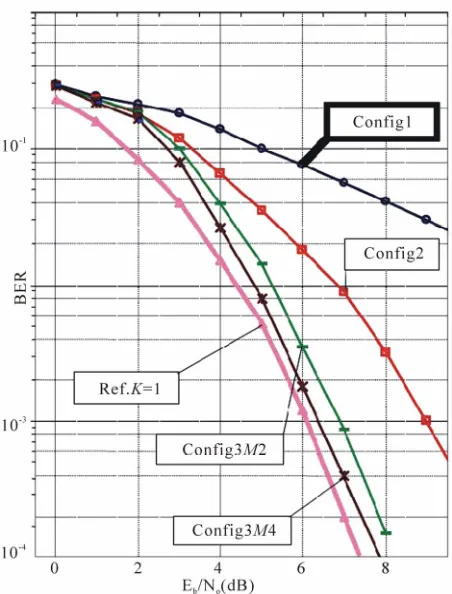
joined SIC detector (M = 2, 3 or 4) and decoder is implemented. That means that the decoder is inside each interference cancellation unit. As we can see in Figure 9, in terms of BER, CONFIG 3 is really more outstanding than CONFIG 1 or CONFIG 2. Now the question is to see whether the complexity increases dramatically or reasonably. That is the goal of this third part.
3.1. Some Words about the Channel Decoding
Nowadays the benefits of channel encoding are well-known: reducing the power emitted and the error rate. Among different channel coding techniques, we find the turbo codes family invented by Berrou et al. [6] in 1992.
On the encoder side, the principle is to code the data with two recursive systematic convolutional (RSC) codes separated by an interleaver.
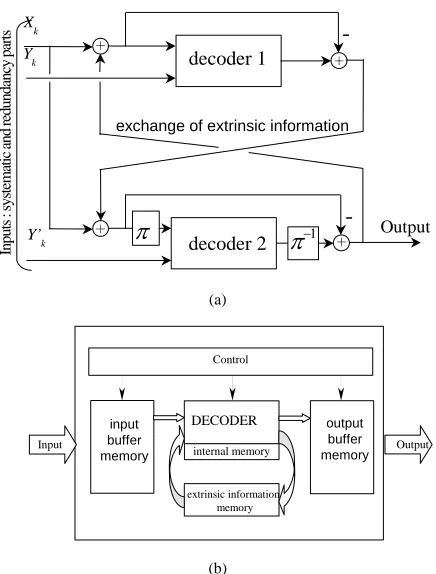
On the decoder side (Figure10(a)), two soft-in soft- out (SISO) elementary decoders work alternately. Each of them benefits from the other through extrinsic infor-mation. The iterative process gives performance close to the Shannon limit. Turbo codes are detailed more in [7].
[image:6.595.310.536.80.377.2]Figure 10(b) shows the architecture of our turbo decoder implementation:
Table 2. Description of the different RAM required in each ICU.
RAM name
size
MY_FA 2 × 8 bits
MY_MRC 1 × 8 bits
M_Ym,k Kmax× 8 bits
Mem,k 5 × SF × 2 × 8 bits
Figure 9. BER vs SNR for different configurations with comparison with single-user performance (spreading Factor = 16, K = 16 users, load rate = 100%).
input memory to store the word to decode, a single decoder to perform the iterative process,
internal memory to exchange the extrinsic
in-formation,
output memory to store the decoded word.
3.2. Conventional Detection (CONFIG1)
At present, detectors implemented in base stations in- volve a bank of matched filters (rake detector) followed by a bank of channel decoders. Then a hard decision function determines the received sequence for each user as de-scribed in Figure 11(a). To ensure reduced complexity, we choose to implement one branch and then accumulate L times. The architecture is shown in Figure 11(b) where it should be noted that the area is around 1900 gates and the processing time is around 110 clock cycles.
3.3. SIC Detector Followed by Turbo Decoder (CONFIG2)
[image:6.595.55.287.626.721.2]decoder 1
decoder 2
Xk Y
k
Y’k
Inputs :
system
atic and r
ed
undancy par
ts
Output
-
1exchange of extrinsic information
(a)
DECODER
Control
extrinsic information memory
Input Output
internal memory
input buffer memory
output buffer memory
[image:7.595.63.281.79.366.2](b)
Figure 10. Turbo decoder (a) principle; (b) architecture for implementation.
FA1 D閏odeur1
FA2 D閏odeur2
FAKmax D閏odeurKmax
1
ˆ
d
2
ˆ
d
max
ˆ
k
d
. .
.
. .
.
decoder 1
decoder 2
decoder kmax MF1
MF2
MFkmax
) (t r
(a)
Rake detector
(implementation of one branch)
( SF+3)×L cycles
Decoder
For L=6 :
TRake = (SF+3) ×L
AvecSFmax = 16TRake = 114cycles / symbole. timing analysis
SurfaceRake =f (SSéq.) = 4500 + 3300 + 500 ~ 8300µm2 around 1890 gates. Complexity
[image:7.595.64.279.425.652.2](b)
Figure 11. Rake conventional detection: (a) bank of matched filters followed by bank of decoders; (b) lowest complexity, implementation of one branch followed by an L-loop accu-mulator.
decoders. To process the complete detection function we can choose between:
Architecture A:Implementation of one ICU and processing K × M loops;
Architecture B:Implementation of one stage of K
ICUs and processing M loops;
Architecture C:Implementation of M stages of K
ICUs.
Table 3 gives the timing and complexity analysis of the three architectures proposed. We can notice that the latency is the same for all the architectures. The process time can be greatly increased, depending on M or K val- ues, except for Architecture C. But the total area is in- versely proportional to the required time to process data. In CONFIG 2, it is essential to implement a memory unit in each decoder as described in Figure 10(b) to allow correct transfer of the received sequence.
3.4. Turbo Decoder inside the Interference Cancellation Unit (CONFIG 3)
As shown in Figure 9, the turbo decoder is placed inside the ICU. This configuration ensures a better estimation before the interference cancellation function. In terms of bit error rate, this structure allows for better results. For the complete implementation, we can also choose be-tween the three architectures A, B and C described in Subsection 3.3. This configuration does not require an external channel decoder, which results in a simpler global architecture.
To process the decoding function, knowledge of the whole frame is required. That is why ICUk processes the
frame before sending information to ICUk+1. This is an important difference from the previous configurations.
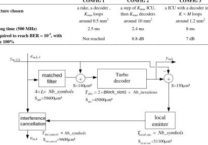
The internal structure of the ICU described in Figure 3 has to be modified as shown in Figure 12. What about the impact on area?
The area of a turbo decoder is around 450,000 m2. The area of the local emitter and the interfer-ence cancellation do not change in comparison with CONFIG 2.
For the matched filter it is essential to implement a combinational structure because we have to proc- ess a whole frame, so the area is increased by a factor of 10.
We have to insert 2 adders.
Thus the computational area of an ICU in CONFIG 3 is around 165,000 mm2 or 37,600 gates including the turbo decoder. The data given in Table 3 are correct ex-cept for the area of turbo decoding, which are now in-cluded in SICU.
833
Table 3. Comparisons of area and timing for the three architectures considered.
A B C
Archite
cture
DecKmax
Dec2
K
×
M loopsICU
. .
.
Dec1
DecKmax Dec2 ICU1
ICU2
ICUKmax
M loops
ICU1,1
ICU1,2
ICU1,Kmax
Dec1
DecKmax
Dec2
ICUMmax,1
ICUMmax,2
ICUMmax,Kmax
Area for SIC detector
SICU SICU × Kmax SICU × Kmax× Mmax
Area for turbo decoding
Kmax × Sdec
Process time f
K M T, , IC U
f
M ,TICU
f
TICU
Latency of
the detector f (K × M × TICU )
Table 4. Comparisons of the different configuration.
CONFIG 1 CONFIG 2 CONFIG 3
Architecture chosen a rake, a decoder ,
Kmax loops
a step of Kmax ICU, then Kmax decoders
a ICU with a decoder inside K × M loops
Surface around 0.5 mm2 around 10 mm2 around 1.2 mm2
Processing time (500 MHz) 2.5 ms 2.4 ms 8 ms
SNR required to reach BER = 10-3, with
load rate 100% Not reached 8.8 dB 7 dB
matched filter
local emitter Turbo
decoder
+ +
ym-1,k
4 × Nb_symbols
em,k
em,k-1
interference cancellation
Tdec =2 × (block_size)× Nb_iterations
Tlocal em.× Nb_symbols
Tint.cancel × Nb_symbols
ym,k
Sint.cancel=9600m² S
local em.=51100m²
SMF=58600m² S
dec=45000m²
S=140m² S=150m²
×L
[image:8.595.99.510.416.704.2]4. Comparison and Conclusions
In the previous section we describe three different con-figurations. In this section, we update the data for a real case study in order to see what can be the best choice. The parameters in the UMTS-FDD context are:
received rate: 3.84 Mchip/s; frame length: 10 ms;
delay from point to point: from 150 ms to 300 ms. To evaluate the required time to compute one frame for a load rate of 100% (Kmax= 16 users and SF = 16), we apply a frequency of 100 MHz or 500 MHz to the circuit. In the case of CONFIG 1, which is the solution pres-ently implemented in the base station, we compare the solution of computing the K users successively or simul-taneously:
The first solution is less complex and it is pos-sible to process one frame in less than 10ms. Indeed, if the clock frequency is 500 MHz, taking into account the results given in Figure 11(b) for the rake and in Figure 12 for the decoder, the delay required to compute one frame is around 5 ms.
If we choose to implement a parallel process to compute the K users, the delay is less than 1ms but the complexity increases by almost K. In the case of CONFIG 2, only architectures B and C described in Subsection 3.3 can compute the frame in less than 10 ms. To optimize the surface in CONFIG 2, we choose to implement one step of ICU and K decoders (Architecture B).
In Table 4, we sum up the performance, area and computing time for the different architectures retained.
Figure 9 gives the performance in terms of BER. We compare the different solutions by indicating the required SNR to reach a BER of 10-3 when Kmax= 16 users and
SF = 16 (load rate = 100%).
The solution implemented today cannot reach the per-formance required in UMTS context unlike CONFIG 2 and CONFIG 3. What is more, the complexity and timing analysis studies show that architecture A can be retained for CONFIG 3, whereas we have to choose architecture B for CONFIG 2. Thus, the final result is that it is possible to implement a turbo decoder inside the interference cancel-lation unit required for detection. Indeed, the area is only three times higher for a beneficial gain in term of BER.
5. References
[1] M. Ammar, S. Saoudi and T. Chonavel, “Iterative Suc-cessive Interference Cancellation for Multiuser DS-CDMA Detectors in Multipath Channels,” Annales des Télé-communications, Vol. 57, No. 12, 2002, pp. 105-124. [2] S. Saoudi, M. Ammar and T. Chonavel, “Dispositif et
Procédé de Décodage de Données AMRC, Système Cor- respondant,” Institut National de la Propriété Indu- strielle, Patent FR 03 14938, 2003.
[3] M. Touzri, “Étude d’implantation de Détecteurs Multi- utilisateurs CDMA: Application à l’UMTS,” PhD: Elec- tronique: Institut TELECOM; TELECOM Bretagne, Uni- versité de Bretagne Occidentale: 2007, 2007telb0031. p. 130.
[4] P. Patel and J. Holtzman, “Analysis of DS-CDMA Suc-cessive Interference Cancellation Scheme Using Correla-tions,” IEEE Globecom’93, Houston, Vol. 1, 1993, pp. 76 -80.
[5] L. C. A. Hui and K. B. Letaief, “Successive Interference Cancellation for Multiuser Asynchronous DS-CDMA Detectors in Multipath Fading Links,” IEEE Transactions on Communications, Vol. 46, No. 3, 1998, pp. 384-391.
[6] C. Berrou, A.Glavieux and P. Thitimajshima, “Near Shannon Limit Error-Correction Coding and Decoding Turbo Codes,” IEEE International Conference on Com-munications (ICC’93), Vol. 2, 1993, pp. 1064-1070.