warwick.ac.uk/lib-publications
Copyright and reuse:This thesis is made available online and is protected by original copyright. Please scroll down to view the document itself.
Please refer to the repository record for this item for information to help you to cite it. Our policy information is available from the repository home page.
By: Yen Ping Cheung
A thesis submitted for the Degree of Doctor of Philosophy
Depanment of Engineering,
University
of WalWick
List of Figures and Tables Acknowledgements
Summary
CHAPTER 1. INTRODUCTION
Page
1.1 Objectives ... 2
1.2 Motivations for the use of AI techniques in Process Planning ... 3
1.2.1 Change in Customer Taste ...•...• 3
1.2.2 The Role of the Mod.ern Engineer ...•... 4
1.2.3 The Nature of Process Planning ... 5
1.2.4 Shortage of Process Planners ... 6
1.2.5 Problems Associated With Experience ... 6
1.3 Relationship Between AI Planning And Process Planning ... 7
1.4 Outline Of Thesis ... 8
CHAPTER 2. PROCESS PLANNING ; TECHNIOUES & SYSTEMS 2.1 What Is Process Planning ... 9
2.2 The Role of The Computer In Process Planning ... 11
2.3 Approaches of Computer Aided Process Planning ... 12
2.3.1 The Variant Approach ... 12
2.3.1.1 The Preparatory Stage ... 13
2.3.1.2 The Production Stage ... 16
2.3.2 The Generative Approach ... 17
2.4 Product Description ... 21
2.4.1 Coding and Classification ... 22
2.4.2 Interpreting CAD Data. ...• 23
2.4.3 Adding Feature To Design ... 26
2.5
Conclusions ... 27CHAPTER 3. AI AND TIlE PLANNING PROBLEM
3.1
3.2
3.2.1
3.2.2
3.2.3
3.2.3.1
3.2.3.2
3.2.3.3
3.2.4
3.2.4.1
3.3
3.4
3.5
3.6
3.7
3.8
The Beginning ...•...•...•...•... 31AI Planning ... 34
Importance of Planning ... 35
What's in a Plan ... 36
Plan Representation .•...•...•... 39
State Space Plans ...•... 39
Representation Of State Space Data Structure ...•...•... 39
Action Ordering Plans ... 42
Plan Generation ... 42
Sea.rch Mechanisms ...•..•...•...•... 42
Green' s Formulation ...•...•....•....••... 46
Kowalski's System ... 51
STRIPS ... 53
NOAH ...•... 56
TW'EAK ...•..••.•••.•.•..•...••... 61
Conclusion ...
66CHAPTER 4. AI TECHNIQUES FQR ASSEMBLY PLANNING 4.1 4.2 4.2.1 4.3 4.3.1
4.3.2
4.3.3
4.3.44.4
Introduction ... 68
Assembly ... 68
Assembly Sequencing and AI Planning ...•...•... 71
Representing Knowledge ... 75
Prod uction Rules ... 76
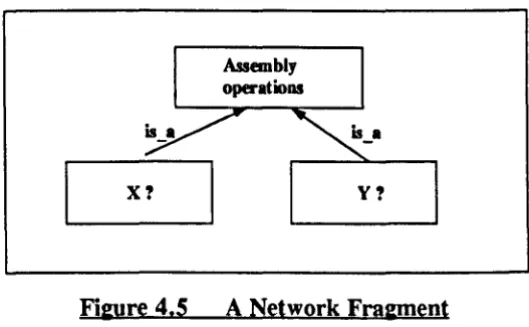
Semantic Networks and Frames ... 78
Non-Monontonic Reasoning ...•...• 83
Predicate Logic and Prolog ...•...•...•...•.
86
4.5 Programming Techniques ... 90
4.5.1 Assembly Planning in Prolog ... 93
4.6 Conclusion .. I • • • • • • • I • • • • • • • • • " I • • • • • I • • • I • • • I • • • • • " I . I • • I • • • I • • I • • • I • • • " I . I . , , • • • 95 CHAPTERS. AN AUTOMATIC ASSEMBLY PLANNER 5.1 5.2 5.3 5.3.1 5.4 5.4.1 5.4.2 5.4.2.1 5.4.2.2 5.4.2.3 5.4.2.4 5.4.3
5.5
5.6
5.75.8
In trod uction ... 97Results of Field Trips ...•... 97
Initial Tests ... 98
The Test Planner ... ~ ... 99
Approach Of The Automatic Assembly Planner ... 107
Initialisation: Input of Goal States ... :~~ ... 1l0 Sequencing ... -... 112
Eliminate Redundant Goal States And Conflict Check ... 115
Generation Of Star List ... 124
Ordering Of The Goal States ... 127
Insertion of Star Goals to Main Goal List ... 139
P od . r uClng ction 1st ... . A' L' 145 Finding The Pre and Post Conditions ... 150
Miscellaneous Clauses ... 156
Ball Point Pen Assembly ... 157
Summary .•.••..•..•....•..•..••••.•.•••.•••.•.•.•..•...•...•....•....•..•.•....• 159
CHAPTER 6. DISCUSSION 6.1
6.2
6.3
6.4 Introduction ... 161The AI Planning Situation ...•... 161
The wgical Approach ...•..•
165
6.5 Philosophical Issues ... 169
6.6 Findings From the Development Of AAP ... oo . . . 170
6.6.1 Assembly Constraints ... 170
6.6.2 Input Description ... 171
6.6.3 Assembly Space Conflict ... 172
6.6.4 !..,evel Of Detail ... ... 172
6.6.5 Additional Reaction Face ... 173
6.6.6 Assembly Database ... 174
6.6.7 Problem Size ... 174
6.6.8 Improving The Sorting Procedure ... 175
6.6.9 Optimization Of The AAP Output ... 176
6.6.10 Other Hardware Platforms ... I • • I • • • , • • I • • • • • • • I • • I . I • • ' " I . I • • • • • • • • • • • I • • • ' " ' " 177 6.7 ussons And Future Systems ... 178
CHAYfER 7
References
Bibliography
CONCLUSION ... I • • • • I • • • • • • • • • • • • • I • • • • • • • " • • • • • I • • I • • • I • • • • • • • I . 184
Appendix
iFundamentals of Theorem Proving and Prolog
Appendix ii
A List of Some Process Planning Systems
Appendix iii Derivation of Formula in Sorting
Appendix iv Test Program For Connecting-rod Sub-Assembly
Appendix v
Sample runs for Test Planner
AI
CAD
CAM
CAM-I
CAPP
CFL
GPS
IGES
MTC
PFA
TMS
Anificial Intelligence
Computer Aided Design
Computer Aided Manufacture
Computer Aided Manufacturing International
Computer Aided Process Planning
Clausal Form Logic
General Problem Solver
International Graphics Exchange Specification
Modal Truth Criterion
Production Flow Analysis
Figure 2.1 An Operation Plan ...•....•...•...•... 14
Figure 2.2 A Simple Matrix With Four Clusters ... 15
Figure 2.3 Dra.wing Entity Record ...••••.•••.•••.•••••...••..•...•• 24
Figure 3.1 Sussman' s Anomaly ...•... 37
Figure 3.2 An Example Of A Tree ...•... 43
Figure 3.3 ...•...•... 47
Figure 3.4 A Refutation Graph For Figure 3.3 ... 50
Figure 3.5 An Example To Illustrate ABSTRIPS ... 55
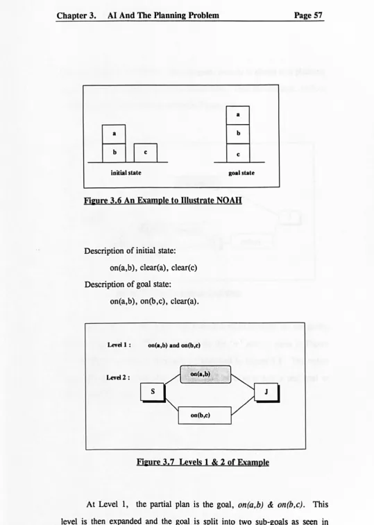
Figure 3.6 An Example To Illustrate NOAH ... 57
Figure 3.7 uvels 1 & 2 Of Example ...•..•.•••...•....•.•.•...•.. 57
Figure 3.8 uvel 3 Before Criticism ... 58
Figure 3.9 uvel 3 -After Criticism ... 59
Figure 3.10 uvel 4 -Before Criticism ...•.•... 59
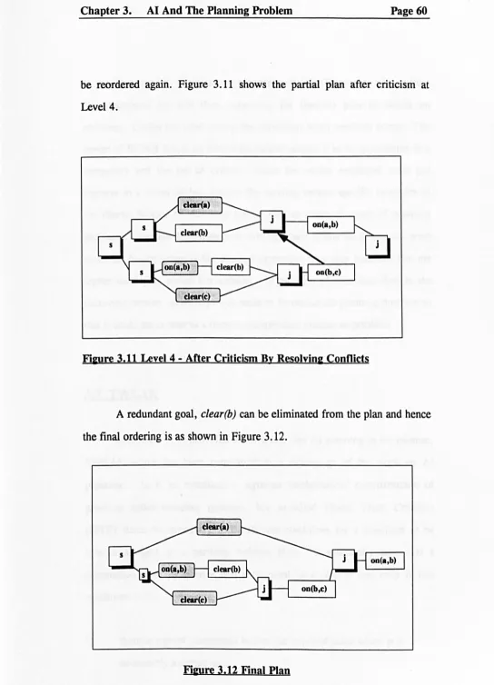
Figure 3.11 uvel 4 - After Criticism By Resolving Conflicts ... 60
Figure 3.12 Final Plan ... 60
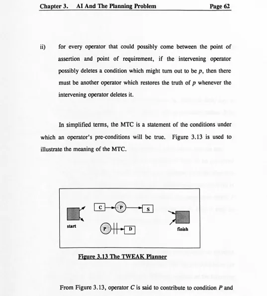
Figure 3.13 The TWEAK Planner ... 62
Figure 3.14 Stacking Three Blocks Onto One Block ... 64
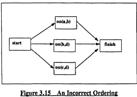
Figure 3.1S An Incorrect Ordering ...•... 65
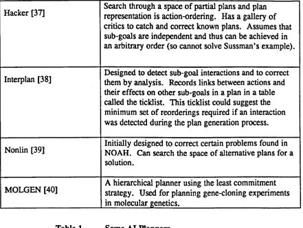
Table 1. Some AI Planners ... 66
Figure 4.1 Hierarchy Of Assembly Process Planning ... 70
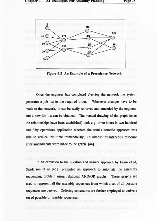
Figure 4.2 An Example Of a Precedence Network ... 73
Figure 4.3 A Simple Semantic Net ... 78
Figure 4.4 A Semantic Net To Illustrate Inheritance ... 79
Figure 4.5 A Network Fragment ... 80
Figure 4.6 An Example Of A Specific Frame ... 81
Figure 5.1 The Piston-Connecting Rod Sub-Assembly ... 100
Figure 5.2 An Initial State Of Piston-Connecting Rod Sub-Assembly ... 101
Figure 5.3 Actual Initial State Of Piston-Connecting Rod Sub-Assembly ... 104
Figure 5.4 Overview of AAP ... 108
Figure 5.5 Redundant Goal Case ..•...•...•... 115
Figure 5.7 Difference Between AAP and TWEAK ... 119
Figure 5.8 Primary Shaft Sub-Assembly ... 120
Figure 5.9 Goal State of Primary Shaft Sub-Assembly ... 121
Figure 5.10 Initial State ... 123
Figure 5.11 C Clobbers Q ... 123
Figure 5.12 A Final Plan ... 124
Figure 5.13 Possible Outcomes For Goals, A & B ... 126
Figure 5.14 A Sequence ... 133
Figure 5.15 A Diagram Ofa Simple Assembly ... 151
Figure 5.16 Post-Conditions For a Simple Clear State ... 154
Figure 5.17 Initial State Of a Ball Point Pen Assembly ... 157
Figure 5.18 A Possible Goal State For The Ball Point Pen Assembly ... 157
Figure 6.1 Types of Goal Relationships ... 175
student, her suppon, advice and guidance throughout the course of this research,·
Professor S.K. Bhattacharyya and Mr. John Fieldenfor accepting as a research student at the Depanment of Engineering,'
SERC for providing me with a studentship to pursue this research,·
Dr. Chris Rinde for teaching me AI and the many refreshing and interesting conversations on the subject,'
Staff at the gearbox Process Planning Depanment, Rover, Longbridge for providing me with some useful practical information,·
My husband, Vincent and my son, James who have both been very supponive of this research,'
computational methods alone are not sufficient to meet these requirements for more flexibility. This research examines the possibility of applying AI techniques to process planning and also addresses the various problems when implementing such techniques.
In this project AI planning techniques were reviewed and some of these techniques were adopted and later extended to develop an assembly planner to illustrate the feasibility of applying AI techniques to process planning. The focus was on assembly process planning because little work in this area has been reported. Logical decisions like the sequencing of tasks which is a part of the process planning function can be viewed as an AI planning problem.
The prototype Automatic Assembly Planner (AAP) was implemented using Edinburgh Prolog on a SUN workstation. Even though expected assembly sequences were obtained, the major problem facing this approach and perhaps AI applications in general is that of extracting relevant design data for the process planning function as illustrated by the planner. It is also believed that if process planning can be regarded as making logical decisions with the knowledge of company specific data then perhaps AAP has also provided some possible answers as to how human process planners perform their tasks. The same kind of reasoning for deciding the sequence of operations could also be employed for planning different products based on a different set of company data.
CHAPfER 1.
INTRODUCTION
The needs of manufacturing industry have changed considerably in recent years due to keen competition at home and abroad. To address these changing needs, computers are increasingly used. This has led to the so called islands of automation within a manufacturing system where each island is an individual department or function in an organisation. There is now a recognised need to link these islands together to form a fully integrated system.
Where conventional computational methods have been fully exploited and exhausted, Artificial Intelligence (AI) techniques could be applied to form this vital link between the individual functions of a manufacturing system. One of the main areas of manufacturing, where computational and artificial intelligence techniques could be applied to improve efficiency is process planning.
machining processes and process planning for assembly. The former type is normally a well defined task where each machining process has its own characteristics, e.g. the speed and feed rate of the process. Most of this information can be found in handbooks or is normally a company's standard information. Thus this is an area of manufacturing where much automation or computerisation has taken place as evident in computer numerical controlled machines. The latter type is not so well defined and is often manually operated. There is also less documentation and also perhaps less understanding on the assembly process. As a result, it is an area of manufacturing where computerisation has been rather difficult to implement.
1.1
Objectives
The objective of this research is to investigate AI techniques that may be applicable to process planning. In order to achieve this the following are needed:
i) investigate what AI planning techniques are appropriate to assembly process planning as there are a large number of process planning systems for machining [1];
ii) implement an assembly planner using AI planning techniques;
Planninl:
1.2.1 Chanl:e in customer tastes
Today product life cycles have been reduced drastically and in some cases, product life cycles may be even shorter than the development lead time1• In order to remain competitive the lead time must be reduced to facilitate the production of new models and to cope quickly and efficiently with additions and modifications. Therefore the whole process from design through to process planning and manufacture must be speeded up. Since the process planning task is the vital link between design and manufacture, computational methods and perhaps AI techniques could be employed to speed up this stage of the production.
Not only have changes in people's requirements made automation of process planning a difficult task but also changes in products and the processes have contributed to this fact. A more flexible approach such as using AI techniques could perhaps be employed to tackle these changes.
The somewhat traditional definition of the engineer2 as defined in the
Chambers concise dictionary bears evidence to the reluctance of the engineering community in applying AI techniques. This definition reflects the traditional nature of the engineering world and the traditional view that we may have of engineering as a whole, i.e. one of solving problems that are of a highly deterministic nature such as design of electrical networks.
However in addition to these traditional tasks, the modem engineer today has to make decisions e.g. planning or making company decisions at management levels that are of a non-deterministic nature in order to keep up with the keen competition and changing tastes of the consumers. Manufacturing engineers in particular have to take decisions on the types of manufacturing processes and the tools to be used. The decisions made at this stage of the manufacturing process can be classified as the manufacturing strategy. Once the strategy has been decided, detailed tactics such as the types of finishings necessary to achieve the specified tolerances and surface finishes, the inspection processes required at each stage can then be made. Even at this latter stage, further decisions or estimates for those phases that do not directly involve a manufacturing process, e.g. transfer of work from one machine or one area to another have to be made. It can be seen that the
level technical work.
Therefore, new aids such as planning and estimation tools should be available to enhance the engineer's work. Few (process) planning tools exist and those that do are analysis tools rather than synthesis tools. They often require existing plans to aid in plan formation of new products. A more flexible planner that is easily adapted to fit different scenarios is required. The planner described in Chapter 5 illustrates how flexibility may be incorporated by using AI planning techniques.
1.2.3 The Nature of Process Planninl:
Due to the nature of the process planning activity as described above, it is therefore not surprising that there is now a severe shortage of experienced and skilled planners. This is because manual planning requires continual re-education about company standards and policies which takes a long time to learn. Even though academic institutions are trying to shorten the period of training to four or five years, there is still a shortage of experienced process planners today [2].
1.2.5 Problems Associated With Experience
It should also be noted that decisions made by relying solely on experience are only approximate decisions and may therefore vary amongst different process planners. This could lead to inconsistencies and recommendations that may be more costly than necessary. Also the experience of process planners may not be directly applicable to new processes and designs. Therefore in situations where planning is often required for new designs, relying solely on the experience of process planners may sometimes not provide the best solution [3].
AI techniques are best at solving problems that are of a non-deterministic3 nature such as process planning. Planning has been a classic research topic in AI for more than two decades. A plan in AI terminology can be defined as a linear or partially ordered sequence of actions to achieve a desired goal. A possible plan for making a cup of tea could be:
fill a kettle with water
bring the water to boil
put some tea into a cup
pour the water into the cup.
It is believed that whether one is devising a plan for making a cup of tea or a plan to manufacture a product as in process planning, the same kind of reasoning must be employed, i.e. that of achieving an ordering of operations from a set' of given operations and constraints. In manufacturing, the operations would be manufacturing processes.
It is also believed that there are similarities in process planning across different domains, e.g. process planning for the machining of components and process planning for the construction of buildings. The former activity
3 Cale. where there are many pOIsibilitea to a aolution, an example i. in medical diagno.i. where .ymptom. could lead to multiple di_gnoli •.
components while the latter involves the sequencing of construction activities for building parts of faciliities [4]. The common feature between these two applications is the logical decisions made in the sequencing of tasks. Thus while the work described in this project originated from the sub-assemblies of the gearbox, some of the work may in principle be applicable to the general problem of process planning.
1.4
Qutline Qf Thesis
CHAYfER2.
PROCESS PLANNING:TECHNIQUES
&
SYSTEMS
2.1
What Is Process Plannin2
The Society of Manufacturing Engineers define process planning as:
'the systematic determination of the methods by which a product is to be
manufactured economically and competitively'
[5].Generally, this involves a series of steps which can roughly be broken down into :
i) Interpretation of the design data which can be in the form of blue prints in the traditional way or on a CAD system.
. ii) Determination of the types of operations or processes; requirements of the products such as batch size, raw material properties, dimensional tolerances; tools for making the products, fixtures plus
any
other special requirements.iii) Determination of the operation sequence.
iv) Calculation of the individual and overall times of the operations. v) Production of the operation sheets (or process sheets).
Therefore process planning is of utmost importance to a manufacturing system and must be completed before detailed costings or further decisions can be made. Once the plan has been drafted all the available information is then passed to the shop floor and production control department where a coherent schedule of the work taking into account the man/machine resources and existing workload can be made. If it is not possible, then the manufacturing engineer may have to revise the strategy to suit the existing situation.
All the above phases of work demand a combination of skilled engineering ~sks as well as much clerical and low level technical tasks, i.e. work of both deterministic and non-deterministic nature. To summarise, the engineer or process planner is faced with a considerable amount of decision making, data references and calculations during these phases of work. Very often the nature of this work is tedious, time consuming and error prone. The errors made could be due to the engineer having to make frequent cross references to data on machine capabilities, process data, company standards, etc.
following section describes the involvement of computers in process planning.
2.2
The Role of The Computer in Process PlanninK
In manufacturing great strides have been made in the development of computer applications in design (as seen in the many Computer Aided Design (CAD) Systems available today) and manufacture (Computer Aided Manufacturing Systems) which was not parallelled by process planning. This situation has also made process planning a bottle neck in the manufacturing process when companies attempt to adopt flexible automation in order to keep up with competition. Until recently this was probably due to the limitations of the hardware and software. Thus the use of computers in process planning was not broadly addressed until the beginning of the 1970's. The first system, CAPP (Computer Aided Process Planning) developed by CAM-I (Computer Aided Manufacturing International) was first presented in 1976 at the 1976 NC conference [6]. After that many similar systems were developed to address this need of integration of design with manufacture. In 1991 it was indicated that 20% of the manufacturing industries would utilise an integrated system of Material Requirement Planning and CAPP and that 50% of the process plans used to produce parts or assemblies would be computer generated [5], Despite the comprehensive list of CAPP systems as shown in Appendix ii, it is currently unclear as to whether these forecasts were or could be realised. As seen from Appendix
2.3
Approaches of Computer Aided Process Plannin&:
Early attempts at automating process planning consisted primarily of developing computer-assisted systems for report generation, storage and retrieval of existing plans. Currently there are two main approaches to computer aided process planning; variant and generative.
2.3.1 The Variant Approach
This approach is comparable with the manual approach where a process plan for a new part is created by retrieving previous process plans for a similar part and then making the necessary changes to the plan if necessary to cater for the new design. However in comparison with the manual approach, this approach is superior in that the information processing capabilities are increased. Consequently, the time required to
search
through existing plans is greatly reduced if standard procedures and company standards have also been incorporated.previously prepared plans are stored in a database. Whenever a new design is planned, a process plan for a similar design is retrieved and subsequently modified by the process planner to satisfy the requirements of the new design. The Group Technology technique is used to code and classify parts into families. A process plan that is used by a family of components is called a standard plan. These standard plans are stored permanently in the database with a family number as its key. The logic of variant systems is based on the grouping of parts into families. Common manufacturing methods can then be identified for each of these families. A family is represented by a family matrix which includes all the possible members. In general, variant systems have two operational stages:
preparatory stage; production stage. [8]
2.3.1.1 The Preparatory Staae
Existing components are coded and classified and the grouped into families and a family matrix is also constructed. Process plans already prepared for these existing components are also summarised. Standard plans are then stored in a database indexed by family matrices.
modification of the standard plans is necessary. In this case, the family size may be very small. On the other hand, if there are many variations in a family, e.g. grouping all parts requiring a common machine into a family, then much plan modifications would be required.
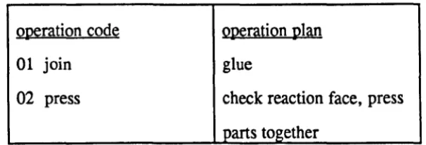
There are two main types of code for coding the parts, i.e. design code and operation code. The design code is equivalent to the design features of parts. The operation code represents a series of operations that are required. Figure 2.1 shows an example of an operation plan.
operation code 01 join 02 press
operation plan glue
[image:25.578.137.440.380.483.2]check reaction face, press parts together
Figure 2.1 An Operation Plan
The coding of part families can be done manually or by using a computerised approach such as Production Flow Analysis (PFA). PFA was first introduced by J.L. Burbridge to solve the family formation problem for manufacturing cell design. [9,10]. In the PFA technique a large matrix is constructed where each row represents an operation code and each column represents a component. The matrix can be defined as Mij where i represents operation codes and j represents components. So, Mij
=
1 if component j has operation code i, otherwise Mij=
O. The objective is toclusters. Thus parts that are grouped into a cluster, belong to the same family.
component code
01 1 1 1 1 1 1 1
Ol 1 1 1 1 1 1 1
03 1 1 t l i t 1 1
.04 operation
1 1
code 05
06 1 1 1
IY1 1 1 1 1 1 1 08 1 1 1 1 1 09 1 1 1 1 1 1 10 11 1 1 1 1 1
Fi~re 2.2 A Simple Matrix With Four Clusters
2.3.1.2 The Production Sta&e
New components are planned at this stage. A new component is first coded and the code is input to the part family search procedure to find the family to which the component belongs. The family number is then used to retrieve a standard plan.
The search procedure is simply a matching of the family matrix with a given code. If a match can be found then the part belongs to the family and the standard plan for the family can be used for that part. The human planner then modifies the plan as necessary to satisfy any new design requirements. New information can also be added to the system but must be managed properly in order to keep the family matrix intact and the database consistent.
CAM-I's CAPP system is a variant system developed by McDonnell Douglas Automation company. It is a database management system written in FORTRAN. The coding scheme for part classification and output format is added by the user. It has a (maximum) 36-digit alphanumeric code.
2.3.2 The Generative Approach
In this approach, process plans are synthesized in order to create a process plan for a new component automatically. Plans are derived from the manufacturing data base without human intervention. The input to these systems would be design data. The advantages of such systems over the variant approach are as follow:
i) consistent plans can be generated quickly; ii) new plans can be made easily;
Hi) has potentialities for linking up to other manufacturing facilities such as CAM, manufacturing management, etc.
either the machined component or the final assembly) an attempt is made to obtain the sequence of operations to satisfy the initial requirements.
The decision logic is the heart of these generative systems. A common approach is to write manufacturing process capabilities in the form of IF-mEN expressions by taking information from handbooks and/or interviewinglO process planners. Decision tables or decision trees have been
used to represent manufacturing knowledge.
In drawing up the decision table, a question is asked at each junction or a decision is made at each junction. An action block is included for each true condition and for a false condition, another branch or process can be directed to the end of the logic block. In computing terms, this is rather like developing a flow-chart for a computer program.
e.g. if al then do nl .... . else if a2 then do ... . else stop.
nl
procedure nl if ....
Decision tables have long been a popular method of presenting complex engineering data. They can be implemented using general programming languages such as FORTRAN, COBOL, PASCAL, etc. This is rather like writing a computer program except that in this case the application is in process planning. In this approach, the logic of the application is embedded in the flow of the program. Therefore whenever any changes in the decisions occur the whole program has to be reviewed again [11].
Another approach is to use AI techniques since the subject attracted much interest and curiosity due to the applications of AI seen mainly in the form of so-called expert systemsll . Most of these systems have implemented manufacturing knowledge in the form of IF condition mEN action statements based on machining processes which is similar to the decision trees approach. Examples of AI process planning systems can be found in [12,13,14,15].
Probably the first AI based process planning system to be reported in the literature, GARI is an example of a rule-based system. It consists of a knowledge base of approximately fifty production rules12 for machining
components. By assigning weights to different pieces of advice, it attempts to find the best answer. The plan generation technique is through successive refinements where it assumes that all machines are available initially. At each iteration new assertions are produced which may then imply a partial
11 A piece of computer program that i. said to be able to derive conclusions and new information based on existing information - something like decision making.
ordering. It stops when it has exhausted the list of active rules by the current set of assertions. EXCAP is another production rule based process planning system for the selection of cutting sequences for prismatic parts. TOM, an acronym for
Technostructure of Machining
is a rule-based system for generating machining(hoZe)
sequences. Hi-Mapp is another AI process planner for machining which is based on manufacturing knowledge that is stored about machining processes.Most CAPP systems e.g. [12,13,14] (whether variant or generative) do not make use of AI planning techniques such as those mentioned in Chapter 3. Ad hoc additions of manufacturing knowledge in the form of if-then rules is a common feature of expert systems for process planning. A more organised approach to this is sought. Therefore, this research had concentrated on applying the fundamental AI planning concepts to assembly process planning.
It can be seen from the large number of computer aided process planning systems available today that the manufacturing logic required for process planning is highly variable. Despite being a highly variable task, the nature of the logic of the sequencing of operations remains fairly static irrespective of the type of application. Hence the application of AI planning research to address this problem is possible.
2.4
Product Description
In the early days, the designer and manufacturer were the same person. As machines and methods of production (working practices) become more sophisticated the separation between these two roles became greater and greater. Today the designer is mainly responsible for designing a new product and the manufacturing phase is further divided into various stages, Le. planning on how to make the product and then actually making it.
The design phase can be divided into two main phases:
conceptual phase (when an idea is conceived);
geometrical phase (where ideas are transformed into a design).
engineering drawing, interpret it and then provide the manufacturer with a set of instructions on how to fabricate the design. This is still very much the case where automation of process planning has been attempted, Le. interpretation of designs is still very much a manual process before relevant data can be input to the process planning system. However in order to achieve full integration of the manufacturing system (Le. CAD and CAM), this interpretation process has to be automated as well. The input format to the process planning system affects the ease of use as well as the capability of the system. A tedious input format would defeat the purpose of automation while inaccurate and insufficient data would reduce the competence of the system. Since this part of the automation process is a vital path to integration, the following sections examine the types of input format available and the types of problems associated with each of them.
2.4.1 CodinK and Classification
small building block of the complete part, e.g. one digit may represent the type of part and another may represent the dimensions. Examples of coding and classification systems are MICLASS [16] and OPITZ [17].
This approach is not efficient in situations where there is much variety amongst products with very few members per part family (as much time would be spent on creating new families and new process plans). Users of such a system would have to be familiar with the coding scheme. Thus the benefits of coding systems cannot be achieved in generative systems which aim to synthesize plans rather than relying on the information provided by coding systems.
As the code and classification concept originates from machining (assignment of codes to parts and part programs - part program for one member of a part family can be used for other members of the family), this method of part description may not be feasible for assembly process planning which do not require the generation of a part program.
2.4.2 Interpretin& CAD data
specific CAD package that was used. This means that different translators may be needed for each CAD package. As can be seen from the technique described below, the translation process itself can be a tedious process.
The devised algorithm for translating 2-D CAD data by Wang [18] consists of defining nine fields in a record to represent each drawing entity,
i.e.
I
line/arcI
(x,y)I
(x,y)I
(x,y)I
radius start end centreFilrure 2.3 Drawine Entity Record
All line and curve entities are extracted from the CAD data file. These entities are then grouped, i.e. all solid lines into one group and all hidden lines in another. The external contour is then recognised by searching through all the solid lines. The lines and arcs (based on the x-coordinates) are then sorted. The basic idea is to connect the line segments so that the ending point of the nth segment is connected to the starting point of the (n + l)th segment. For example, the rule for recognising a straight cylindrical type of surface for a pair of adjacent points, n, n + 1 is:
ifxn
<
xn+l and Yn = Yn+lwhere (xn, xn +
1>
are x-coordinates of points n, n + 1However this method was based on a 2-D wire frame model and would not work for 3-D models. Also wire frames can sometimes provide ambiguous interpretations (e.g. which is solid and which is not). For accuracy, interpretation of a 3-D model is preferred. This would require even more tedious algorithms which may only be feasible for the CAD system on which they were developed. At a gross level, this means that new algorithms would have to be devised for the (many) different CAD systems available. This defeats the aim of flexibility.
2.4.3 AddinK Feature to DesiKn
Another possible approach is to specify explicitly the features of the parts during the design stage. Thus enabling the encoding of feature based information with the design. This requires the direct design of parts using features (instead of the conventional method of using lines, arcs, etc.). Such features (in the ready form) are then stored in the system's library which could be used for process planning. This kind of system may however require a lot of human interaction such as verification of results. Presently similar CAD systems using a knowledge-based approach are available in the market but their credibility would require further investigation.
These so-called intelligent CAD systems provide a design language for the designers to create new designs. The data generated from these new designs can then be used and/or manipulated in a manufacturing environment.
2.4.4 Questionl Answer Approach
2.5
Conclusion
The process planning task can be sub-divided into two main parts, Le. the decision on the types of manufacturing processes to be used and the ordering (or sequencing) of those manufacturing processes. As different manufacturing systems vary in their decisions on the types of manufacturing processes to be used, no one single process planning system can satisfy all of the different manufacturing needs. Hence, in order to achieve the first sub-task of the process planning activity, manufacturing databases pertaining to the individual needs of manufacturing systems have to be created. As suggested in Section 2.3.2 that common knowledge can be found in handbooks such as [24] for machining (unfortunately very little has been written on assembly), but company specific data (such as that on special processes that originate from the company and is possibly a trade secret) has also to be obtained from the company itself. System developers adopting the expert systems approach have suggested various methods of eliciting the relevant knowledge from the process planners. As knowledge elicitation is another major subject by itself and is also appropriate to the generative approach, further comments on the subject are included in Chapter 4.
variant approach is more useful if the manufacturing system makes similar or identical components for perhaps different types of assemblies.
The generative approach is recommended when there exist many variations among the types of products made which makes it difficult to code and classify them into a relatively small number of families. However for a moderate number of component families and moderately sized manufacturing systems, the variant approach may well be the most economic automated planning system alternative at the moment as variant systems are better understood than generative systems. Therefore, variant systems are cheaper, easier and faster to develop. On the other hand, if the situation is such that a high degree of flexibility is needed (such as frequent changes in designs) and integration of a CAD system further upstream with a CAM system is desired, then the generative approach is the ultimate solution. As mentioned in Section 2.3.2, very few truly generative systems are available today, so companies adopting this approach should be prepared to spend much time and effort on a technology that at the moment is still developing.
features (such as grooves and slots) as well as topological and geometrical data. On the other hand, option of interpreting CAD data could also involve much tedious programming which may have to be changed whenever the CAD system is upgraded or replaced. The controversy of which is the better approach, i.e. directly interpreting CAD data and describing features through independent means (like question and answer type or incorporation of feature information with design) still remains. However the final result of both approaches must be that the method to obtain the information should be simple and easily applied to other situations and at the same time information must not be over-specified.
Sometimes the simplest approach is the best and also the cheapest. The possible extension of the question and answer approach is to deduce a minimum number of questions that can be asked in order to obtain answers to the relationships between mating pairs. This could be classified as a kind of knowledge acquisition exercise and would involve much time spent with a willing process planner at the company concerned. In order to avoid disrupting the normal routine of the company, a plausible arrangement could be to co-ordinate the work of the person eliciting the knowledge with a process planner who is about to retire and whose time and effort is devoted solely to this project. This is because past experience has suggested that no matter how cooperative the expert may be, he/she is bound to be called away on another more
urgent
matter.have to be adapted for assembly purposes. As for generative systems, there is no standard input format and the form of input usually depends on the approach used by the individual process planning system. A question and answer (as in expert systems) type of interface is the most commonly used at the moment. It is believed that in the long term, future design systems should invariably contain some elements of manufacturing data which could be of use further downstream, e.g. process planning.
CHAPfER3.
AI AND TIlE PLANNING PROBLEM
Machines that characterised the Industrial Revolution in the 1700s were machines that helped extend and multiply people's physical capabilities. Today, people are confronted by a different category of machines that are said to extend and multiply human mental capabilities, Le thinking machines. Whilst the former type of machines met much in the way of opposition (such as the Luddite Movement founded in Nottingham in 1811 which perceived these machines as a diabolical danger to the workers of the textile industry), the announcement and creation of the latter types of machines were met with mixed feelings. While humans accept that machines could perform physically better (since birds can fly and humans cannot), it is more difficult to accept machines that equal or even better human mental capacities. The study of these machines which is closely associated with the way the human mind (or brain) works is therefore the prime concern of Artificial Intelligence or AI.
based on such interactions of basic particles then the decisions too must be pre-determined.
In more recent times, Ludwig Wittgenstein (1921) described human thought as comprising certain elementary facts in his first major work, Tractatus Logico-Philosophicus. In his model there are propositions about relations between these elementary facts and also certain allowable transformations on these propositions to yield composite propositions. In simple terms, we cannot think what we cannot say; we cannot say, or ought not say what is meaningless in the language that we are speaking. He has made two major points that have a direct bearing on the intellectual roots of AI, i.e. he made a direct link between human thoughts and a formal process that can be described as computation. This was re-stated two decades later in the Church-Turing thesis at the famous Dartmouth conference in 1956. It asserted that if a problem presented to a Turing machine is not solvable by that Turing machine, then it is also not solvable by human thought. This formed the basis of the AI movement and until today the measure of the intelligence of a machine is still the Turing test. An interrogator can ask questions of either the person or the computer but does not know which of them is which. The aim is to determine which of them is the person and which is the machine. If the machine succeeds in fooling the interrogator to believe that it is the person, then it can be concluded that the machine can think. Some people believe that no machine will ever pass the test due to the complexity of the human mind!.
There are many definitions to the term AI and it is still very much a topic of debate today. The definition of
anijicial
is easily taken care of bymachine
but it isintelligence
which is difficult to define. This can be illustrated by the fact that so long as a problem remains unsolved and retains its mystique then it is said to require intelligence to solve. However once it is solved and one knows how it works then it does not seem to be any different from any other piece of computer program (therefore it does not require intelligence). Amongst all the definitions of AI, perhaps the most valid definition is:the study of computer problems that have not yet been
solved,
by Minsky since the 196Os. This is certainly the case in AI planning.From a practical point of view, AI can be defined as:
The
study of how to make computers do things which, at the
moment, people are better [25]
Therefore as a branch of Science, it is concerned with developing concepts and vocabulary to aid the understanding of intelligent behaviour in people. In terms of engineering, it is the task of engineering a technology of thought, Le. it is concerned with the concept, theory and practice of building intelligent machines (e.g. expert systems, vision systems, etc).
the former the knowledge to solve a problem is implicit in the algorithm whereas in the latter knowledge is explicitly defined (as proposed by Plato and Wittgenstein). Since it is explicitly defined, an AI program is said to be more flexible than conventional programs in that new and relevant knowledge can be added to the original programs for new applications. In the case of conventional programs a completely new program would have to be written for different applications.
3.2
AI Plannin&
Much of AI planning research has concentrated on domain independent planners, i.e. developing plan representation and plan generation techniques that are expected to work on a reasonably large variety of problems. In general, the study of AI planning involves the computation of a sequence of operations to perform a specific task before it is actually carried out. For example, the recipe for baking a sponge cake is a plan. Thus a plan consists of a sequence of operations or instructions to perform a task.
AI planners were applied and tested on simple robot manipulation domains such as the Blocks World.
In the Blocks World there is a set of labelled blocks (usually A, B, C, etc), a table with infinite space on which the blocks rest and a robot which performs simple block manipulations. The only move allowed is either to stack a block onto the top of another block or move a block to the table. The constraint in the system is that a block can only be moved if it and its destination is said to be
clear.
Also the top of each block has only enough room for one other block and the robot can only handle one block at a time. Examples using blocks described in subsequent sections will be based on the Blocks World.3.2.1 Importance of Planninl
This technique is said to simulate human problem solving behaviour [27]. Therefore, besides developing planners for military purposes, it is also the intention of AI planning to shed some light into how the human mind works which at the moment is still a mysterious domain.
As mentioned, everyday life planning is an essential aspect of intelligent human behaviour. Apart from preventing fatal consequences, the planning function is also at the heart of a manufacturing system. It is essential for making the system work in the first place. Through ingenious planning, the system is able to manufacture at a competitive cost and thus ensure a place in today's keen market.
3.2.2 What's in a Plan
A plan can be one of the possible solutions to a problem. Planning is easy and straight forward if tasks or goals can be decomposed into disjoint (or non-conflicting) sub-goals. So these sub-goals can be achieved in any order or in parallel. Problems occur when there are conflicts between sub-goals. Consider, a simple planning problem consisting of two sub-goals say, Gl and G2. It might be possible to solve it by doing Gl first and then G2. However when doing G2, Gl gets undone. The same situation might also exist by doing G2 first and then G 1. A classic example where one sub-goal
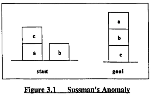
In Sussman's example, there are three blocks,
a,
bandc
as shown in Figure 3.1. The goal consists of two sub-goals, i.e. stack b onto c and stack a onto b. In the initial situation, c is on top of a which is on the table while b is on the table with no other blocks on top. A computer planning program would consider each sub-goal in turn. In order to achieve the first sub-goal, i.e. stack b onto c, this could be done by directly stacking b ontoc.
Buta
is underneath both b andc,
therefore the first sub-goal cannot bedone first. If the second sub-goal is considered first, then
a
must have no blocks on top. Thus, c is un stacked and put onto the table. Once the top of a is cleared then it can be put onto b to achieve the sub-goal. But, the goal requiresc
to be below blocks b anda.
Therefore, it is also not possible to start with the second sub-goal.•
c b
a
I
bI
cstart loal
Fi&Ure 3.1 Sussman's Anomaly
[image:48.575.176.429.463.622.2]Unlike most AI problems, conjunctive planning cannot be solved by just using well known AI methodologies such as divide-and-conquer as illustrated in the example above. In order to tackle this type of problem, the planning problem must be considered as a whole rather than as independent sub-problems or perhaps, to solve G, a bit of Gl has to be done first followed by doing a bit of G2, then finishing Gl and finally finishing G2. However
some problems (if they cannot be broken down into sub-problems) may be too large to be solved in practice [28]. To date very little, if any, of this work has shown any impact on real world problems. Instead the work tends to be limited to research laboratories and is based on the Blocks World examples. As research in AI planning has been going on for more than two decades, there is now a rich and growing armory of AI planning systems. The existence of the large number of AI planners today is evidence of the competitive spirit in this field. However little effort has been made to apply these planners to real world problems which were considered as unchallenging and uninteresting.
3.2.3 Plan Representation
There are basically two main types of plan representation techniques: state space plans and action ordering plans.
3.2.3.1
State Space Plans
A problem is often characterised by state descriptions. The situation/condition of the problem at each stage of its solution is defined by a state data structure. A state is a snapshot of the problem at a given point in time. Operators are used to transform the problem from one state into another. At different times, the problem is said to be in different states.
There are three types of states in a state space representation scheme, i.e. initial state, goal state and intermediate state. The initial state is the state at the start of the problem and the goal state is the problem in its final state, i.e. the state of the solution to the problem. The intermediate state is any the state that exists between the initial state and the goal state.
3.2.3.2
Representation
Qf
State Space Data Structure
symbols and then doing reasoning about that knowledge by manipulating those symbols in various ways. Predicate Calculus is a form of symbolic logic that allows us to express logical concepts (meaning of sentences or utterances) and then manipulate them using various rules to obtain new knowledge from old (Le. making inferences). This is normally used by logicians, mathematicians and philosophers. Thus the meaning of sentences is a proposition which consists of terms, of which there are two types, predicates and arguments. Predicates are relation names and usually correspond to verbs in sentences and arguments are the objects that are related and usually correspond to nouns. For example, the sentence, Block a is on top of Block b can be represented as:
deduction. AI planners are thus deductive systems rather than inductive2 systems which involve the assignment of probabilities to reasoning steps.
It is also possible to combine individual statements to form compound propositions by the use of logical connectives. These include' and (1\), or
(V),
not (,), implies (--
»
andequivalent
(~). To further extend the system to represent the notion ofsome
andall,
two quantifiers, universal (V) and existential (3) are used.\t
is called the universal quantifier because it talks about everything in the universe and.3
is the existential quantifier because it talks about the existence of some objects.Due to the complexity of Predicate Calculus, it can be very difficult to represent in a computer. The programming language, Prolog, used in modelling the Automatic Assembly Planner (AAP) described in Chapter 5 is based on a simpler version of logic called Clausal Form Logic (CFL). Prolog consists internally of a program that carries out deductions using symbols such as objects and relations to manipulate its set of data (database). Fundamentals of CFL is covered in Appendix i as it is the basis of the language used to implement AAP.
Thus by using a form of logic, the meaning of the state data structures could be represented in a computer. Similarly, the state space representation can also be represented in a computer as a directed graph
2 Inductive ayltellll are important where much uncertainty existJ aa in medical diagoo.ia ay.lema and ay.lellll to
where the nodes in a graph describe the states and the arcs describe the application of operators which will transform one state into another.
3.2.3.3
Action Orderina Plans
Another form of common plan representation technique is the action-ordering plan representation in which the planner attempts to produce a sequential list of actions which are limited by constraints. The actions are written down in a list and are executed in the order in which they have occurred on the action list. NOAH described in section 3.6 is an example of an action-ordering planner.
3.2.4 Plan Generation
The most common approach to the formulation of plans is to search the space in which the problem is represented. The search procedure is probably all the reasoning that is required of the planning system.
3.2.4.1 Search Mechanisms
always selected for expansion. In the latter strategy, the search proceeds by examining all possibilities of a node by going across the search space before proceeding down into the next level.
b
/\
e r
/\1
pd e g j k s
FilWre 3.2 An Example of a Tree
The depth-first search with backtracking is a simple method of considering alternative solutions. The state of the solution at each point where there are alternatives is saved together with the alternative choices. If
a failure occurs, the saved state at the last decision point is restored and the next alternative taken (if there are none, backtracking continues over the previous decisions). The programming language Prolog uses this strategy.
In the least commitment strategy, the central idea is to leave partial solutions incompletely specified until the last possible moment. When as much information as possible becomes available, then the ordering is completed such that no conflicts arise (this is also used in the NOAH planner).
Assumptions, alternatives or dependencies can also be added to the set of data and then treated like any other piece of data. Whenever a conflict exists, only the dependent parts are undone leaving unrelated parts intact. This approach is called dependency-directed backtracking.
In meta-Ievel planning, a separate search is made to decide which of the operators is best applied at any point before detailed decisions are made, Le additional reasoning about the various techniques available for generating the plan.
The search mechanisms described above have evolved over the past two decades and are characteristic of planners developed over that period. The search can be difficult due to the large number of interactions between different states or partial plans. These interactions can lead to a surprising amount of complexity as shown by Gupta and Nau [29] that the problem of finding an optimal plan in the simple Blocks World domain is NP-hard3•
Also the establishment of the existence of a pre-condition in a partially ordered plan can require exponential computation [30]. Thus planning problems are considered hard and are still a topic of AI research.
If the planner searches through an action-ordering plan then it can add and remove operators at various points in the plan as illustrated by NOAH in Section 3.6. In the state space representation, modification of the plan is only possible at the end of the plan. Here operators are added to the plan by trying out another operator application and operators are removed when backtracking occurs. Thus the kind of reasoning or search involved depends on the representation technique used. In the following sections,
3 In Computer Science, lhe economy of an algorilhm i. mellured in terml of lhe complexity mealUre. of time and memory lPace. E.g. the bubblelOrt algorilhnm i . . . id to be a quadntic time algorilhm. UnrealOnable algorilhma are .. id to require IUper-polynomial or exponential time. There are a cia .. of problema called NP-complete where their lower bound. are conceivable but have exponential upper bound.. An eXlmple i. lhe
some significant AI planners and their techniques which are relevant to AAP are described.
3.3 Green's Formulation
Green [31] first formulated the planning problem using Predicate Calculus and applied a resolution4 theorem prover to generate plans. His
formalism involved a set of assertion SS that describe the initial state and another set that described the effects of various actions on the states. A situation or state variable was included in each predicate in order to keep track of which facts were true in which state.
The system then attempted to prove that there exists a state in which the required goals are true. The essence of his method is rather like afill in the blank resolution where a correct plan is derived as a side effect of proving the existence of a correct plan. In addition, it is also necessary to state that certain relations are unaffected by the actions (assertions for each relation that is not affected by an action must be included, otherwise the resolution proof fails). These assertions describe what stays the same during an action and are called frame axioms. This technique is often referred to as the Situation Calculus. The following example illustrates how it works.
4 The rolOlution principle i. described in Appendix i •
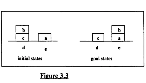
d e d e
[image:58.575.138.415.140.298.2]initial state: goal state:
Figure 3.3
From the above figure, the formulas for the initial state are:
The goal state is:
on (b,c,sO) on (c,d,sO) on(a,e,sO) c1ear(b,sO) c1ear(a,sO)
on (c,d,sl) on(a,e,sl) on(b,a,sl) c1ear(c,sl) c1ear(b,sl)
The fact that block
a
is in positione
can be written as:where sO is the state in which a is on e is true. In this case sO is the initial state and sl is the goal state. The action of moving a block from one place to another can be expressed as: move(x,y,z) where x is moved from position y to position
z.
After executing an action in one state, the result is a new state and can be expressed as: do(action,state), i.e. map a state into the one resulting from an action. It is also necessary to indicate that two blocks are different in order to prevent the situations like e.g. on(a,a) from occuring. Hence difJ(b,a) can be used to suggest that b is different from a. Thus the rule in this problem is:clear(x,s) &: clear(z,s) &: on(x,y,s) &: difJ(x,z)
=
>
on(x,z,do(move(x,y,Z),s)) &:clear(x,do(move(x,y,z),s)) &:
clear(y, do (move (x,y,z),s)). (Rule 1)
Rule 1 can be read as:
if
x
and Z are clear and ifx
is ony
in state S and ifx
andz
aredifferent, then
x
andy
will be clear andx
will be on Z in the state resulting from performing the action of move(x,y,z) in the state s. The difJpredicate does not need a state variable because its truth value is independent of state. The refutation graph for this example is given in Figure 3.4.The main drawback of this approach is the need to write down formulas for each relation that is not affected by an action. These formulas are called frame axioms. A frame axiom for the above example is:
Convert Rule 1 into clausal form: .on(c,d,sl) ., clear(x,s)
-, on(a,e,s 1) ., c1ear(z,s)
Negate goal: -,on~) -y on(x,y,s)
-,clear(c,sl) -,diff(x,z)
'c1ear..ft(sn
on(X'Z,d~eX'Y
,z),s» 1Clear(X,d~e(X'Y'z),S)
z=ax =b clear(y ,do(move(x,y ,z),s»
'l=do(move(b,y,a)'T:---clear(b,s)., clear(a,s)...,on(b,y,s)
-, diff(b ,a) y=c
clear(y ,do~,y ,a) ,s» s=sO,
=
>
si = do(move(b,c ,a) ,sO pon(c,d,do(move(b,y,a),s»pon(a,e,do(move(b,y,a),s»
~
".
trclear(c,do~4(b,y ,a),s»
~
----
Match with initial states :""'\~(b,s) ~(a,s)~c,s) clear(b ,sO) ,c1ear(a ,sO) , .,diff(b,a) on(b,c,sO), &
on(c,d,do(move(b,c,a),s» s -= sO
on(a,e,do(move(b,c,a),s»
~
~
~
I
diff(b,a) , on(c,d,do(move(b,c,a),sO» on(a,e,do(move(b,c,a),sO»l
Evalute diff predicate]
~
on(c,d,do(move(b,c,a),sO» on(a,e,do(move(b,c,a),sO»
[Match with initial states: on(c,d,sO) and
on(a,e,sO).
J
[N~
3.4 Kowalski's System
Kowalski (1979) offered a different formulation using Predicate Calculus which simplifies the statement of frame axioms [32]. He used a predicate, holds to indicate that a given condition holds in a given state. For example, holds(on(a,c),s)) is the same as Green's on(a,c,s)). This means that the number of frame axioms needed is equal to the number of operators. So the initial state for Example 3.3 is:
poss(sO)
holds (on (b,c),sO)
holds (on (c, d) ,sO)
holds (on (a, e) ,sO)
holds (clear(b) ,sO)
holds (clear(a),s))
poss(sO) means that state sO is possible, i.e. one that can be reached. Effects of the actions (post-conditions) are also specified as follow:
Another predicate, pact is used to represent the fact that it is possible to perform a given action in a given state, i.e. the pre-conditions of the action match that state description. So, pact(a,s) means that it is possible to perform a given action, a in a state, s. A rule for the action, move is:
(holds(clear(x),s) cl holds(c1ear(z),s) cl holds(on(x,y),s) cl diJ!(x,z) )
=
>
pact(move(x,y,z),s).It is also necessary to define the pre-conditions, i.e. if a given state is possible and if the pre-conditions of an action are satisfied in that state then the state produced by performing that action is also possible.
So,
poss(s) cl pact(u,s) =
>
poss(do(u,s))Here, only one frame axiom is needed for each action. Hence for the example in the previous section, the frame axiom is :
(holds(u,s) cl diJ!(u,clear(z)) cl diJ!(u,on(x,y))) =
>
holds (u, do (trans(x,y, z), s)).