COSC 460 Project Report
Deptirtrnent of Computer ~;c:i ence Uni ver:::i
ty
of Ctinterbur~dA
Di.aqnl-tnnl€-r
fot-
tf1ef.xsys
Data.
tlodcl-~3upervi :::or : Dr. R. E. ~1. Cooper
Tab[c. of eontc.nts
1. Introduction ... 1
2. Backqround to Problem .~, ... L.
2. 1. E;<svs ... 2
2.2.
Theo:svs
Data t"'lodellet-
...
4
2.3. Docurnentation and Diagrarn::; ... 4
2.4. OH1er Vlort=: and Related Areas ... 6
3. Di agrarnrner Design ... 8
2J.1. Overall Desiqn ... 8
Autornat i c Gener-ation ··· 0 r. -:;:~ ._;_.,_ .. Entity Placement 3.3. 1.
o· ...
·ervi 81h' ... 1 0 3.3.2. Past T ecr·mi ques ... 1 1 3.3.3. Chosen r·-1eH1od ... 113.3.4. Improving the A1gohthrn ... 13
3.3.5. Attr-action and the P1acernent Prottlern ... 15
3.4. F.~e lat i onshi p Placerrtent 3.4.1. Introduction ... 17
3.4.2. Past Research ... 18
3.4.3. Chosen t·1etr1od ... 20
Aestrtetic Requirements and Effects ..-{·"-t ... .L.L. 4. lrnplernentation ... 23
4.3. Building Trees . ... 25
4.4. ... 26
4.5. Entity Pl e;c:ernent •")7
• · · · • • • • • • • • · • · · · • • • • • · • · · · • · • • · · · • · • • • · • · · · k. I
4.6. Reltitionsrtip Ple;c:ement ... 2Ei 4.7. Line Printer Output ... 30
5. Results
emd
Future '•,n,-'orr.~ ... 325.1. Results 7·?
•••••••••••••••••••••••••••••••••••••••••••••••••••••••••••• •••••••••••••••••• · · · - · · · ._J .&...
5.2. Li rnitt~t ions ··· 32
5.3. Future '•,n,·'orl< 77
. . . ._! ._}
6 .. [:onc:lusions ... 35
7. F~ef erenc:es ... 36
Adt~ta User F~elease on Di aqrarnrner Appendi>-~ A A data User r·1anua 1 for Di aqrarnrner Appendi::.: B
r(,r."'.J.f'""' Entit!-! P1acernent Cornp1e:":i1!-! Derivation ... Appendi>:: C
u ·~ \
~---~--·~
Sorne Diagrams ... Appendi:><: D
L
i f:i i nq of ·-Di
aQrarnmer Code1. Introduction.
This project involved the design and implementation of a diagrarnrner
for EXS'l·'S .. 5 recent sofb'·tt~re product for the desi !~n and construction of
bLls..tness~--S~:Isterns.
o:svs
t~utornates the sy::;terns ant~ i ~dsi s process em d ..through a series of ansv·ters supplied t1y a user .. creates a Data r·1cuje l of the
user's t11Jsi ness etr·li ronrnent. Tt·1e di C!!~rarns cree~ted using the proposed
di agr-arnmer consist. of tu:txes and 1 i nes which represent .. respective 1 y_. the Entities and Rel at i onst·,; ps ;,·vrti ch make up an DS'y'S Date~ t'1ode 1.
The ret~sons why t1 di t~grarnrner is needed for Er~SVS .. t1 description of
the environment in which the die~gr-ammer will run, t~nd conventions
regm-di ng hov·,·· di Cl!~rarns at-e use,j to repr-esent Data t·1ode 1 i nf orrnati on, are
covered in Section 2. A f orrnu1 ati on of ¥that suc:t-1 a di aqrarnmer st·1oul d do
is prirne~riiy dictated by EXSVS' users requirements but sorne mor-e sutrtle ..
ar11j ,jifficult to quantify, e~:pectations arise from the fact that diagrams
are meant to be ref!d and understood t1~ humans ratr1er them machines. Tr1e
theoreti eel consi dere~t ions involved in designing the di agrarnrnet-, these
aestJJetic expectations .. e~nd their effect upon the design of the diagre~rnrner
are discussed in Section 3. A description of trre implernentt~tion of tr1e
,ji ~Jgrarnmer ~Jnd some dett~il s (such es ,jt~tfl structures) of the rnethcuj of
i rnp 1 ernente~t ion are descri tted in Sections 4.
Section 5 discusses the results of U1e ··1\'·ork ,jone on tr1is project and
mention::: future ~Nork needed both to i rnprove on wht~t. has been done t~nd to expend H1e diflgrarnmer to make it t1 full product. In Section 6 .. conclusions
2. Background to Project. 2. 1 EX:3VS.
D:S'r'S is a soft ,~,..are prcujuct trei nq createrj ernj marketed
\·vorl
d\Ni de t11~~ ~
Adata Softvtare Lt,j_ of Christchurch to tre used in the fie1d of creatinq
·-cornp 1 ete business systems \·Vithout the nee1j
r·
or the tradition a! rnethcnjs of soft ware rjeve l opement. D::;'y'S remove::; U1e neerj for v·tri t i ng anrj test in!~letrge system programs a 1 togeU1er arnj effective l ~d does av·tt!!d ;Ni th the
usual four-step software development process t1r11j r-epleJc:es it witJ1 a si n~~i
e
step process.Desi qn r·'Jodul e
--·-Dt1tt1 t'lcuje 11 in!~
Attribute Detail
Data r·'lani pul e~t ion ::,_ F orrnul ae Condition t1cuje 11 i ng
Procedure 0'·lePli ew Procedure i1ode 11 i n!=j ._
Runtime S~dstern
.Quer-y F e~ci 1 i t!d
Fig. 1. t··lakeu~;;r of EXSVS
As is sho\·Vn in Fig. t) EXSVS is rnarje up of a [)esign portion .. a nmtime systern) and a query facility. The Design portion of
D:sv:;
consists of threeme~i n sect i ems :
1. The Data fvlode
n
er_. v·thi ch is used to build an Ent ity/Re l e~ti onshi p Dobi Model of 5 business environment (a discussion of theD::S\·'S Data t'·1ode
n
er- and the Ent ity/Re 1 at i onst·fi p rnethorj of Data2. the Attribute Detoil section •nhich is used to define .. for eoch
AttritnJte in the Dt~tB t-·1odel, its type (monetary_. numeric, etc),
its storage form in the User datatrese .. end its defeult screen onrj
re~~or-t f orrnets ond prornpts/heeders, ond
3. the rnodul es used to define ond construct the trusi ness
system to tre used in the environment modelle,j using the Dato
t'1odeller (the definition of this S!JStem is stored in the
Procedure Model).
The Runtime s4stern uses the inforrnotion in the Data end Proce,jure
t··1ode1 s to ani rnate the t1usi ness S!JStem in the same manner as an
interpreter for ::;orne high level language nms a ~WO!~rarn. Ho\htever, this
analogy is not completely correct because the Runtime system does not
interpret single ····statements" as an interpretet- does trut, instead, \·vorks
1Nith each Procedure as a unit. Also .. once the Runtime System has loaded a
Procedure's ,jescription from the Procedure t'1ode1 .. it ¥till perform the actions given for that Procedure at speeds com para ttl e to compiled
programs. Procedure Descriptions ar-e cached by the Runt i rne Systern so that the overhead of loading them only occurs the first time the Procedure
is used.
The C!uer!J facilit!J .. provides for ad-hoc requests about information in
the User datattase. These requests .. f"lowe'·ler .. are given in English (that is .. a
manager can sirnply sit down and type in an English request li~~e .... what are
the names of a 11 bache 1 ors in the Purcha::oi ng Depar-trnent ?" and C!tJery ~rti 11 answer it to Ute trest of its ability). The atlility of the Query system to
understand words like ··bachelor' must tre supplied by defining such words
in terms of items in U1e Data t-"lodel (for example, Employee sucr1 that
2.2 The D:S'r'S Data fvlode 11 er.
Of particular re 1 evance to this report is a description of the EXSVS Data t·1odeller and the philosoph~ behind its construction. The
o:svs
Data i"'lorjeller is trased upon the Entity/Relationship '·iie\h,·' of Data t·-todellin!l· formalised in Information En!~ineering disciplines (see [ 15]). Tr·1e Entity/ Re 1 at i onshi p phil osphy is the view that a user's 'Norl d-pi cture trei ng modellerj i:::• trn:~rje up of things (eg. Customer .. Branch_. etc) called EntH1es .. characteristics of these Entities (eq. Custorner Address) ca 11 ed Attributes .. and relationships between Entities (eg. Custorner rnakes aSt~le) called Relillt1onsh1ps.
The
D::SVS
Data tv1oden
er has bui 1t in U1e e:><:perti se of e>::peri encedsysterns analysts \'Yt-lict-1 is userj to create a Data t'lodel try asking the user-questions about the business environment he or she is modellin!l This Data t'1ode 1 c:orrectl y meJtches the user's perception of this environment and is easily changed if the user is not satisfied. The Data t'1odei is elso fully norrneli sed (to 5th Norma 1 Form) as the Date Mode 11 er detects atternpt::• by the user to define a non-normefl i serj Data t-tode 1 anrj he 1 ps them to redefine it tretter-. The Data !'lode 1 created usi nq U1e Data r·1ode 11 er is userj as U1e
basis for a database for user rj5ta (U1e User Database).
2.3 Documentation and Di aqrarns. ·
understood.
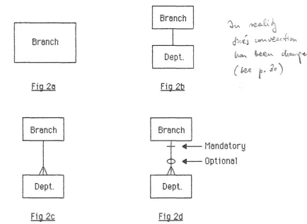
The ide a of using di agrarns to represent i nf orrnati on is not new. CotV·lentions for r-epresenting Entity/Pe1ationship Data nodels using
diagram::; ewe given in t·1e~rti n t;,_ Fi nkl estei n [ 15] e~nd are desc:ri bed bel ow (see Fig 2). To a person acquainted with these conventions, a great deal of
information attout a pen-ticulerr Data f'1c"jel can be conve!Jed by a diagrarn of
that ~-1odeL
Brernct·t
Fig 2a
Branch
n
I '•
Dept.
Fig 2c
Branch
J'\A
I
J:.,.,;.~Dept. &<,...,_
(t~
Fig 2b
Branch
-r- ..___ r-·1antjatorq
c :. ..___ Dptionerl
/\
Dept.
Fig 2d
}'\
'
(J
;:.._~..tJ'\..
r·
2Q)
An Entity is represented b!d er ttox with the Entity's name vvitrlin (Fig
2a). Relationships are represented b~J lines between the boxes of the tv ... ·o Entities involved in the Relationship (Fig 2b). Information concerninq U1e
nature a particular Relationship is 1jrawn at tr1e points ·vvhere the
Relationship lines join onto the Entit!d boxes using lines_. circles, and
crows feet.
A Relationship can tte defined in tvvo directions (eg_. ('l~ranch is made
1m of Department·'·· .. and ((Department is r;1art of Branch·'·'). In each
,jirection_. a Relationship t·1as tvvo pieces of information which define its
[image:8.600.120.555.252.569.2]noture, nomely :
One/Many: represented tty o crows foot (en- the lock of), ond
OpHonol/Mtmdatory: represented tty, respectivel~d, o circle oro line across Ure Relation::Jrip line. The One/t'ian~d nature of o Relationst·rip (in one of its directions) rjefines
1rthether
em
instance of one of the Entities i nvo 1 '·led in the Re l at i onshi p mops onto "one at mo::;f' or {,·many'·' instances of the other. n·ris is best illustrated using the exomple atrO'·le (and Fig 2c):.... A Branch is made U!;t of many Departments-", and
····A Department is Qart of a Branch'·'.
The Optional
I
r·'1andatorq nature defines whether an instance of one of Ure Entities involved in the Relationship rnust map onto ''.at leost one-" instance of the other or not. This is i1lustrate1j using tJre same e~<arnple(emd Fi!=~ 2d) :
,.{A Branch is rne~de U!;;' of (possibly) mt~ti!d Departments'-'_. emd ····A Department is 6n3rt of (neccessarily) one Branch'·'.
Other- conventions exist that define how special Relationships such as
t·'lutue~lly E~~clusive or t'lutually Contingent Rele~tionship pairs e~re
1ji agrarnrned. However_. these are not required to tre discussed in trri s report
since Hre diagrammer does not at present deal ··.·vith diagramming special
Re1 at i onsrri p i nf orrnat ion.
2.4 Other \N'ork and F~ele~ted Areas.
The use of di agrarns to r-epresent Data f"lo,jel s is stande~rd practice
1Nith systems ant~lysts. Hm·vever_. t~n aid to genert~ting such dit~gratrrs_. tre it interactive or automatic_. is e~n e~ree~ that he~s treen neglected. Of course_. the
intere~ctive construction of diagrams is similar in concept to rrli3n~d other interactive applications such as logic simulators [
1
L
[21.
chip lt~yout). \n/hen studied mcrr-e deeply_. hm·-tever .. it becomes t~ppt~rent Utt~t
Ute t~utornt~tic construction of diagrams im··olves not only the problems
reco!~nised and ,jealt with by these fielljs t1ut is also affected b!J tJ1e major
considerations of the readability of diagrams, ho\'v informative they are ..
and their aesthetic value. These considerations have a large influence on
the methods used to so l'·le the obvious prot1l ems det! lt with in those other
fie ids (see Sec.
3.5\
t1ut.. due to the1
ack of work in the area of thegenerations of data rncujel diagrams, no reset~rch can be found which
3. Di e~gre~rnrner Design.
3. 1 Over-e~ll Design.
The overe~ll design of the functions of this diagrammer was largel!d
determined tty Ute expectations of its interujed users. Becouse of the
docurnentat ion purpo::;e::; of di e~grarns .. the users reqtli re that di agrarns are
atrl e to be generated quickly {ei U1er i nterac:t i ve 1 y or autornat i can ~:I) and then displayed or printed on some output device like 5 terrninal or a
printer. A 1 ::;o_. the user requires that di e~gre~rns t~re t~b 1 e to be stored for
perio1js of time, e~rnj later retrieve1j_. so Utt~t rnodifications can be
perf orn1e1j on thern .. or corn pari sons rna de to e~ssess tbe effect of c:t"n:n·t!Jes
to the De~ta t1ocle 1. Thus the user vi ev·ts the ide a 1 di t~gre~mrner es in Fig. 3.
Load ,/ Save / Delete Diagrams
Genere~te a Di egrarn
-Automatic
- Interact i'o.··e
t·'1odify t1 Diagram
Output a Diagram
- Line Printer
-Plotter
-Graphics Terminal
Fig. 3. Functions of U1e Ideal Dlagramrner
3.2 Autornt~tic Genemtion.
Given the user expectations of the fet~tures tht~t a dit~grammer should pro'·li de, the next step is to decide the best meU1ods for an i rnp l ernentt~ti on of such a diagrt~mmer to use in fulfilling them. Tt-,e primt~ry function that a
diagrammer should provide is the facility to genere~te a diagram.
Additional facilities such as storage_. retrieval} and output of dia!;~rarn8 ..
theoret i ct~l protr 1 erns. Si rnil t~rl y, the deve 1 oprnent of t1 graphics S~Jstern for
interactJ\.·e genert~tion e~nd rnorjifice~tion of diagrarns belongs to an area that has treen dealt with tty many researchers [ 1
L
[2] and .. tte!JOnd thespecifict~tion of user cornrnt~nds t~nd actions .. is also t1 task w·ith no ret~l
problems to be solve1t
The t~utomt~tic generation of rjit~grarns, on the other hand .. was recognised soon t~fter beginning work on this project to be t1 problem of
considert~ble size t~nd scope. It has rnt~nw sirnilt~rities \.Yith such aspects of
CAD e~s Printed Circuit Board design, Integrated Chip layout, and Interior Design. Two prottlems are generally recognised by reseatT~1ers in these fields:
1. Tt·1e determining of positions of objects to minimise some distance function on U1e 1 engths of connections bet v·teen them (eg. circuit part, transistor, and room positionst and
2. The construction of the connections betv·teen these ot,jects so as to rninirnise such Htings t~s vias .. corners, and crossings.
In the t~utomatic generation of dit~grams, the corresponding tasks are the positioning of the Entity boxes, and the construction of the Relationship lines ttehveen U10se troxes.
Si nee d"ii:~grarns t~re intended for human consurnpt ion .. the autornt~t i c generation of diagrams also invoh··es prot1lerns in attempting to duplicate the rnental processes involved ¥then, say_. a draug~1tsrnan draws up a diagram of some Data t·1ode 1. These mente~l processes must t1e i dent Hi erj and duplict~ted in order to genet-ate diagrams that not only .... look neat" an,j r.·look: rigt1t") ttut also in v ... ·hich U1e information at,out the structure of a
3.3 Entity Placement.
3.3. 1 Overview.
The first prott 1 ern in the outornat i c generet ion of a di egrarn is that of deterrni ni ng U1e positions of Entity boxes on the di egrern. \¥e require tht~t
the positions of Entity tto~~es t~re chosen so tht~t, t1ecause of the need to
later place U1e Relationship lines between Entities_. the distance t1ehveen
Entities is minimised. This is an application of a prot!lern recognised in
many fields (such as management science_. engineering, and corntlinatorics)
'Nhic:l"1 is known as U1e Otu:u:lratlc Assignment Problem (C!AP). \lariou:::
restrictions on this protrl ern qi ve rise to such re 1 t~ted prot•l ems as the
Component P1 a cement Protr l em [9L the Backboard ¥/iring Prob 1 ern [22], and
even the Travelling Salesman Problem [9]. The C!AP is also researched
under the name of the Placement Prot!lem [24].
The Quadratic Assignrnent Problem is usually stt~terj e~s t1eiow:
Given: a set of locations l
= {
x
1 .. --- ..xn
t
a set of elements S = { s 1 .. ___ .. sn } to be placed_.
a connection matri ~< C:
= [
c1 j ] to representconnections ttetv·teen elements of S_.
find: a permutation of location assignments P = { P 1...---.. Pn }
so that
n
n
' ' 1-.
*
d fF•· F'·J··L
L
-·ij
'.
LJ
i=l j=i+1
is minimised (· ... vr1ere d is sorne qener-al distance function Y.;tliCJI
computes tr1e "distance" bet"-.·veen t"tto 1 ocau ons).
Tt-,is, in printed circuit t1oard terms, rnay correspond to finding
3.3.2 Past T echni gues.
The QAF' wa::; first reco!~nised try Kooprnans .~~- Beckman [12] in 1957.
At first researc:t·, on the QAP was concentrated on finding exact solutions
using branc:h-and-bounrj techniques (eg. Gilmore
[BL
Lavl"ler [ 13]). It soonbecame otrvi ous to reseat-ct·1ers that, due to U1e e~~ponent i ell nature of anw
general procedure to gives exact solutions, progress in this area \·vould tre
slo"Tt except for a clt~ss of highly restricted SJJb-pr-otrlerns (e~~act
procedures trecorne cornputat ion ally i neff ecti ve when the size of the
problem (n)
>
15). Effort was soon diverted to finding fast.. good ..sub-optimt~l heur-istics for this pr-oblem.
Sutr-optimal rnethods that have been proposed for the QAP are :
(1) Constructive methods .. v·lhich place one or more elernents at a time to truild up a complete placement,
(2) I rnprovernent rneUwrjs, which seek to i rnprove t1 given p 1t~cement by exchanging several elements ..
(3) Rela~{t~tion methods .. 'l·thich use the ····forces}.' on an element due to its connections v·iitt"l other elements to ret~ch a point of minimum tension,
( 4) l next~ct Etranch and Bound methcujs, \·vhi ch ,jevel op trounds on the cost of assigning an e 1 ement t1 long \·Vi th trt~cktrt~cki ng if the seot-ch e 1 ong t1
trranch of the decision tree bei nq created does not prove to tre useful.
An e~<cellent review of the 'Nork to 1970 is given in Hanan Cr.. Kurtzberg [24] ar11j Burkard & Stratmann [25] review the v·mrk to 1978.
3.3.3 Chosen ~-lethod.
As stated a 1 ready_. the di t~grarns genert~ted by the di agrt~mmer ar-e
i ntenderj to be vi ewe,j tr~J humans. /J, consequence of this is that the en-rangement of Hte entities t~nd relt~tionships on t1 dit~grt~m is required to
be sucr1 tt1et relt~ted entities are close to one t~noH1er and that reletion~;hip
lines generally cross as little as possible end are as short and straight es
t~i rns t~re more i rnportt~nt tht~n the f orrner (Entity). Tr1i s rnet~ns tht~t_.
ellthough o t-eosonobly good method of plC!cing Entities is requirerj_, beyond tJ
certain point the degree of difficulty involved in placing difficult
Re1t~tionships is not reduced b!d irnprovements in the optirnt~lity of the
ple~cernent of Entitie::;.
!'lost of the algorithrn::; ,jevelope,j to provide a solution to the QAP have t1een developed with the purpose of giving a solution that is fe~ster
and gives rnore optirne!l results for certe~in standard test protrlerns the~n e~li
previous algorHhrns. The incree~sed optirne~lit!:l of such an algorithrn is ustwlly onl!d t1 small ge~in an,j_, given U1e ree~sons for wt-,ich a C!AP algorithm
is required_. is of duttious que~lit!:! compared to the e~dded cornp1e~{ity of a
pro!~rarn writ ten to i rnp 1 ernent it.
\&lith this in rni nd_. the rnethod that Wf:JS chosen for use within the di 5grarnmer is a rnodifi cation of U1e 5 l gorithrn propose1j t'!d Garside s,_
Nicholson [7] in 1966. Tr1eir method is essentiall!:! 5n iterative construction a 1 gori
Unn
f o11
0\·ved by 5 peli rwi se excr1ange i rnprovemente
l goritbm. It WfJS intended to i rnp 1 ernent the iterfJt i ve constructionalgoriU1rn 5nd to add the pair-v·tise exche~nge a1gorithrn later if it proved to
be a vv·orUr·Nhile addition. However_. the time complexity of the pairvvise
excJJt~nge
algorithrn proved to t1e IJ slow O(E 3) per iteration~ttith
IJn unknoY.tn nurnt,er of itere~tions \·vl-iiC:i"l vv·as decide1j to be too costi!d for the very srnf:J l1 i rnprovernent pro'·ii 1jed. (E ar11j F.~ are use1j in U1i s report to stanrj for, r-espectively_. the nurnt,er of Entities 5nd Rel5tionsrlips to t1e placed in U1e diagram).1. Choose the Entity most related to those 51 ready p 1 aced.
2. Test for- placement at eac:t-1 position
(a) if empty- compute the cost of placing the Entity here_. (b) e 1 se - test U1e Entity al rea,jy there at e~ll ernpty positions
and compute cost of the p1acernent plus displacement. 3. Place the Entity at the position which gives the lowest cost.
The iterative construction algorithm tBken from 13Brside t;,. Nicholson's paper is given in Fig 4. Taken literall!d.· this algorithm has 5 time
complexity of approxirnt~tely O(E4) (cf. Gilmore's N4 ar11j N5 alqm-ithms) an,j} applied to tr1e situation in
D:svs
wt·,er-e a very large nurnber of Entities are e!llowed and must therefore be accounte,j for in the design of a di agrarnrner .. definitely needs improvement t1ef ore t1ei ng used.3.3.4 lm6troving the Algorithm.
The iterative construction elgorithm given by 13erside
tr..
Nicholson can be improved in hvo ways. In any generel method for placing Entities} the number of positions for p 1 eci ng Ent i tes in must be et 1 ee::;t as rnan!d as the possible nurnber of Entites able to be placed.D:svs
ellov·ts a maxirnurn of 900 Entities at present so as rnany possible Entity positions on a diagrem must be made aveileble. To check every position woLJld not only tte slow but is elso intuitively wron!~ since when e new Entity is pleced (vttlict-1 is releted to other-s on the diegrem) its finel position will necc:esserily be near or adjacent to those already placed. This rneans that an ot,vious impr-ovement to the algorithm is to limit the atternpts at placing an Entit!d to positions \Ni thin extremes given tty the positions of tr1ose Entities alreenjy placed.Tr1e second improvement arises frorn the fact that the original algoritrnr1 tests if the ,jisplacement of an Entity already placed on the
ditl!~rern v·till impro'·le tt"le finol diagn::~rn. However, the earlier an Entity is
placed on tfie diagr-arn, U1e less likely that its displacement \·vill t1e profitable. This is tteceuse, for any Entity, the positions of all Entities p 1 eced later wi 11 be dependent upon its position. A wey of deter-rni ni ng which Entities are worth etternpting to displace (and hence removing wasted effort on those whi c:h are not) could i rnprove the al gorithrn b~J up to em order of E.
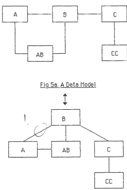
A gocuj method of accomplis~-,ing this is to first t1uild an augrnented
and then to restrict displt:~cernent Btternpts to those Entities v·those depth in the tree i :::; greC~ter tht:~n or equa 1 to the depth of the Entity being p le~ced.
Trlis trreadth-first tree is constructe,j
t1y
follo\·ving relationships frorn u-,e Entity itV·lolved in the most RelationtJ,ips (the root) to construct each layer of the tree. This meems that Entities at the second level of the tree_. say, are a minimum ofhvo
Relationships distant frorn the root Entit~J- The Entities at each level of the tree are connected to those in the above (faU1er) and trelow (son) levels and to tho::;e on the same (brother) level. This covers all relations;t-,ips tretween Entities in the tree. An e>::arnple of aData f'lc11jel and the corresponding tree is given in Fig 5.
r--A
EiL.-,---~
c
AB
cc
-!
B
.
A
AB
c
cc
Fig. 5tr Tt1e equivalent tr-ee
This method of c:onstructinq a trreadth-first tree is quite effective at
[image:17.602.160.418.287.674.2]correspon,jence tretween the occurenc:e of Entities in the tree and the order
in which they ore p 1 ace,j on the diagram.
The final algorithrn used for Entity placement is given below in Fig 6.
1. (Pre~rr-ocess). Determine the nurnber of Pe1ationships each Entity is involved in.
2. (Tree truild). Build o trt-eedth-first tree (with cross links) of the
Data lylodel try the rnethcnj discussed obove. Each Entity has a
depth ossoci a ted with it.
3. (Placement). Pepeat E times.
( 1) Choose the Entity rnost re 1 a ted to those a l rea,jy p 1 aced. (2) For each position in the area given try the minimum and
maximum x andy positions of those elreed~J placed.
If empty- compute the cost of placing the Entity there.
Else if the Entity there is of a higr·,er depU1 than U1at trei ng p lt~ced - try next position.
Else- for et~ch position eJ~; before wiU1 noU1inq plt~ced
in it - compute the cost of moving the Entity to this position and t~dd it to the cost of placing the
first Entity in the second Entity's old position.
Fig. 6 Fint~l algorithrn fcrr- Entity_Qlacernent
3.3.5 Attraction and the Placement Problern.
The time complexity of the improved algorithm used t1y the
diagrammer to place Entities is O(E5/ 2) (see Appendix C for a derivation
of this estimate). This results in slm·v e~~ecution when E is large (up\·vard of 50 Entities) and a better method would be appreciated.
A new approac:h to the P1ecernent Problem (em alternative forrnulation
of the QAP), based on Force equations derived from C1 assi col t·-1ec:t"1ani cs is
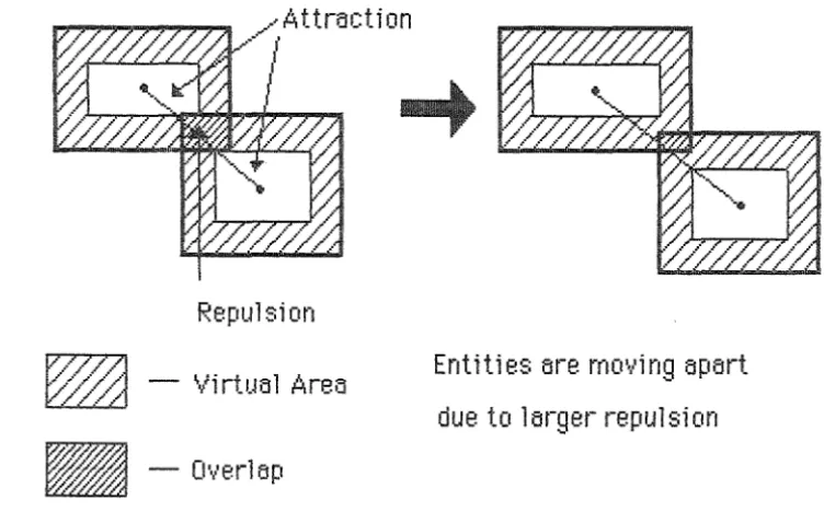
for goorj routin!~ methods for the problem of placing Relationships. It is si rnilar to re la~~tlt ion methcnjs [6] given for H1e QAP but the notion of vi rtueil area is ne\~t. This method.. given sorne reasonattl e initial configuration, uses iteration to derive a stat,le final configuration with changes in e 1 ernent positions cal culate,j rJsi n!~ for-ce equations bosed on attraction bet ween connected e 1 ernents and repulsion t1et vv·een ··(overlapping.'} elements. Damping is applied so that an equilit,riurn position
\Ni 11 t1e a chi eve1t
The attractive forces are based on the idea of a sprinq between element that are connected and increase linearly with the distance between connected elements. The repulsive for-ce can be based on either repulsion t1et vteen a 11 elements according to the inverse square la\·V or can t1e t1ased on repulsion trehveen elements \¥hose vi rtua 1 areas overlap. An element's virtuol t~rea can be compared to personal space, is proportional to U1e numt,er of connections frorn the e1ernent, is alvtays larger- that the
t~ctual size of the e lernent. Y./ith Uli s virtual space repulsion the size of
the repulsive f orc:e is proportional to the overlapping area.
Some method of determining that, try and large, most elements' vi rtua 1 spaces do not overl tiP in the equil i trri urn position is needed to cornp l ete Quinn's rnethod (this can be achieved b~J slowly i nc:rei3si ng the
Repulsion
- ~lirtual Area
-Overlap
Entities are mo'·li ng apart due to larger repulsion
Fig. 7 Forces and their Effect on Entity Positions
This method
e~ppecws
very prorni sing due to its order esti mote (O(E2) per iterotion with fe\~' iterations needed) and to the fact that the virtuol areo concept (allo\"'ting rnore room 1.1round the more highly reloterj Entities) will ollow room for situ1.1tions v·thich using the present method ofinfle~,:itr1e grid positions would become very congested with Relation::J1ip
lines. Un~nJppily_, due to time and priority limitations, it \¥as not possitde to irnp1ement this rnethod to test its usefulness.
3.4 Re 1 at i onshi j:} Placernent.
3.4.1 I ntrodu~:t ion,.
[image:20.600.90.466.42.276.2]Assignment Problem t1y t·1ory-Rauch [16] who applies it to the field of computer printed ci t-cuit board 1 ayout. Ho\Never .. it seems that this protr 1 ern has more relevt~nce to the field of diagram construction than in the field she applies it to si nee the position and function of pins on chips are usual1 y predeterrni ned try U1e rnanuf ac:turers.
3.4.2. Past Research.
t1uch reset~rch ht~s treen performed in the fie 1 d of routing 1i nes : first in the t~ret~ of rnt~ze runners t~nd 1 t~ter for the purpose of autornt~t i ng the i t~yout of i ntegrt~ted circuits. This reset~rch t~ll ori gi nt~tes from the
t~l gorithrn proposed try Lee [ 14] in 1961. This t~nd other et~rl y t~l gorithrns using the Lee technique t~nd/or \·Vt~vefront strt~tegies [4L [21] ~Nere slow
t~nd consumed large arnounts of stort~ge. The next mt~ j or t~dvance ct~me from Hi ghtm·Yer's [ 11] escape 1 i ne a 1 gorithm. This, using tracktn:~c:ki ng when t1
dea,j enrj is react1ed .. calculates the 1i nes perpendicular to and crossing a par-ticular 1 i ne se!~ment to \ftorf( out the 1 i ne segrnent to be tr1e next part of the line being routed. Once a line has been route,j, a series of improvement
are performed to isolate the corners of the line and H1en to remove overshoots.
The eventual descendant of Hiqhtower's escape line alqorithrn is the ~ ·-1 i ne e:x:pansi on a 1 goritt1rn developed t'~d Heynes, Sansen t;, Beke [ 1 0 J in 19Ei0. This a 1 gori thm is based on the expansion of a 1 i ne segment in the direction perpendicular to it to give
em
expansion zone (see Fig 8). This expensi on zone contains all U1e points that can tre reached t'!d follo'vving a line perpendicular- to the line segment being expanded and its edges will t1e either existing line segments or nev·t ····active lines·'' to be e~<panded further. Expansion is carried out frorn each of the two endpoints of the line to t1e routed and stops when the expansion zone of one of the endpoints meets the expansion zone of the other. The line seqrnents of the route,j line can ....carried out on one or- t\~w layer boards emd ¥till find a solution (if one exists) in which the number of corners in the 1 i ne are rni ni rni sed.
ill""""""
F ; ; : : ;;
---~3
:::::::::::::
!J : : : : : : : : : : : : : : : : : : : : :
IJ~
-t
t
x1 v?
"·~
~
- Active 1ine · · · - Expansionzone
He!dnes' algorithm needs some modification before it can be applied to
the area of placing Relationship lines for the automatic generation of diagrams. This is because ·when 'Norking on one layer the algorithm alloY·ts no crossings ··Nhatsoever and ··Nhen ··Norking on tv·Eo layers crossings are ano··Ned since the crossing lines 'Nill be on different layers. The ideal situation envisaged for placing Relationship lines v·tould ano··N crossings if their e:~~istence ·were justified by an appropriate reduction in corners and distance.
This line e~<:p;:tnsion method ··Nas under stwjy for implementation at the termination of this project.
Other ne·vv methods that are being ,jeveloped for use in the area of
routing an,j maze running are multi-contoLn-ing algorithms and c:!"Jannel and ri\.•er routers [ 18]_. [23]. The mutli-contow-in!~ al!~orithm of Dobes [3] places each line ··1Yith no regard for obstructions and then ··stretches·· the line to
avoi1j them. The channel an,j river routers, v·thic:t-1 seern to tte rnost useful for the placing of ··Nires on computer PCEi's, deal v'fith wires to be routed by deciding Y·Ehich ((channels'·' (or gaps behveen chips) the ·wire may be laid along an,j by H1e use of quick ··rip up an1j relay' algorithms fin1j::; solutions
3.4.3. Chosen Method.
The main intent of an e~utomatic: line r-outer such as that proposed
fOt-H1is project is to successfully route all lines \·Vr1ile rninirnising such
things as vias} crossings and comers. For the purposes of the diagn:!mrner_.
the lines representing Re 1 at i onsr1i ps ewe required to t1e constructed so that the resulting diagram is as clear as possible. To irnplement U1e
construction of Rel at i onshi p 1 i nes It decided that Y.lork should first be done on a ,jir-ect_. deterministic scr1erne to be augrnented emd/or replaced
eventually t1y a general line router at,1e to place a11 lines regardless of
complexity (the comple~<ity of a line corresponds quite closely to the ,ji~;tanc:e tretween the Entities at et~c:h end of the line). There were three
reasons t1ehi nd thi ::; choice :
1. No 1 i ne router of any repute had been found at the t i rne work sten-ted on Relationship p1t~cernent}
2. The direct placement scherne \·vould give some insight into the
arrangement of Entities on the diagr-am for future work on a
generel router .. and
3. The methods used to place the simplest Relationship 15!douts
could t1e used later instead of invoking the gener-el router-.
The eventue;l general router must be atde to bslanc:e H1e U1ree limHin!~
factors of the length of H1e line .. the nurnt1er of corners in the line_. ar11j the
number of c:rossi ngs
H1e
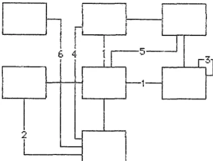
1 i ne causes against one another to give Ute best ple;c:ement for eec:h Relt~tionship.The direct router- takes its design frorn the fact H1at an infle:x:itlie
!~rid is used for placing Entities. This grid means tr!iJt the t1oxes
representing Entities will appee;r on tr1e diagram like chips on e~ computer
PCB. Since Entities are ple;ced so thet releted Entities are more likely to
t1e close together, each Relationships in the disgrern can be classed
Q
6 4
2
Fig. 9 Re 1 at i onshi 1:1 Tyr;;1es
( 1) Strafgfit line ..
(2) One corner ..
(3) Self Relation,
(4) Sarne rov·t or column .. not ;:!lj_iacent,
(5) Ne~-.;t ro··N and ne;.-~t column,
(6) Ne~<t rov·t or colUmn .. far a··Nay_.
(7) ou·,er (wtlicr' the router ,joes not attempt to place).
This ,jivision of Relationships is sufficient for smaller Data ncujels
arnj !Jives a ver-y fast, useful line placement rneUro,j_ Ho-..·vever, a::: the
nurntrer of Entities in U1e Data r-1ode1 increases to at,ove around fifty_. tt1e
numtrer of Class 7 Relationstlips and the nurnt1er of Class 4 to 6
Relationst·,ips not placed due to congestion t1egin to increase rapi•jly. Tt·,e
original intention v·ras to v·,·Tite a more general router to place U1e rejects
of tt1e direct router but it vv·as later- decided U1at suct1 an general router
should t1e v·.·Titten (when one v·tas foun1j) to place an relationships in U1e
same manner (the direct router could still be used U1en for placing very
[image:24.598.193.405.48.208.2]3.5 Aesthetic Reguirements and Effects.
Be~dond the Cispec:ts of Entity iJnd Re 1 Cit i onshi p p 1 ;Jcement CO'·lered tty methods for solving the C!AF' an1j routing prot!] erns are the addition a 1
consi de rations of readatlil ity_. i nf ormtlt i veness, and aesthetic: va 1 ue. An!d iJtternpt at defining methods to deiJ 1 vvith these consi deriJti ons will neccessari 1 y dup 1 i cate assumptions made b!J a person \Nhen they dra\·V a diagram. it was decided that there are hvo ways in \•Vhich the diagram
could t1etter fulfil the at,ove requirements :
1. Allo¥t the Relationship(::;) ttebveen Entities to influence the
relative positions and orientations of u·1e Entities, and
2. t·-love ttl ocks of Entities around to create room so thiJt more
Relationships are atrle to t1e dra·wn simply.
The first of these goals can tre satisfied try creating ···lriases···· for eBcf"r of
the Ent i ty/Re l at i onshi p/Ent i ty corntli nations that require a part i cul
at-re 1 at i ve positioning. These t1i ases ce~n tre added to any a 1 gori Uwn for
ple~cing Entities b~d returrring an artificially high distance velue between
hto Entities when their relative positioning is not the~t required.
It should t1e noted H1at the tri e~ses chosen for- use in the di agremmer are pure 1 y ex peri menta 1 and may not eff ecti vel y reflect the assurnpti ons
ac:tw:~ 11 y mt~rje by systems iJna 1 ysts.
Tt1e second of these goals \f\o'as four11j to be too difficult to deal "Nith
effectively for two reasons:
1. It require~; tr1e atrility to move large blocks of Entities around on the diagram with the aim of reducing tt"le cornple~<ity of
Relationships, iJnd
2. It requires U'te diagramrner to possess knov·tledge about the real
\Norld (for example trusinesses) wt1ich is not directly obtainattle
from the information stored in the Data t1ode1.
The use of this knowledqe is displa!-fed b!-1 a S!-fsterns anal!-fst v·then he or
-- ·- ._, --
·-she groups together Entities \Nt·1i ch seern to have no obvious 1 in~~ trut !;JO
4. 1. User Interface.
diagr-ams v·thich differ in the selection of the Entities and Relation~J1ips to t1e di agramme,j. These four types of di agrarns, Entity Centr-ed.. Entities involved in a Procedure, Entities in a Functional Area, and Complete Data t'lc"jel .. were chosen to provide a grading of size and cornplexity of ,jiagrams. Two of the diagrarn typE:s are simple to e~~plain out of the EXS'y'S
conte~·~t: these ar~.Cornplete Data f"'lode}g;rfmd Entity Centred diagrams .The Entity Centre,j ,jiagram is a diagram of the Entities and Relationships \·vitt"lin a certain nurnber of Relationships ,jistant from a particular Entity (the u:::er inputs t10H-1 U1e Entity to centre the diagram on and the number of
F.~elationst1ips to follo\·V out frorn U1at Entity). The otber t\No types of
~jiagnHYlS (the Proc:edure and Func:tiona1 Aree type ,jiagrems) need to be
e~~p1ained in the
D:svs
context. In the Procedure t1odel in EXSVS are defined Functional Arees (an equivalent concept to schema or sub-schema) andProcedure~; (v·thich mu~;t_ belonq to a Func:tion51 Aree). Entities are involved
in the Input and Output
ff
of a Procedure (it is these Entities that are diagrammed for an .... Entities involved in a Procedure·'' type diagram). The Entities in the ··'Entities involved in a Functional Area" type diagram t~reall U1ose Entities involved in eacrt of the Procedures that t1elong to a particular Functional Area.
The user, after choosing the type of diagram they wish to do .. must answer questions to completely define the diagram (Utat is, things like a Procedure name or t~n Entity name). Tr1e steps involved in this are described in [5]. Once all the::;e questions are answered the automatic diagram generator is invoked and the Entities and ~:eletionships are placed. Once a diagram has been generated the line printer output routine is called end the diagram is ~rtritten to a disk file an,j may tte printed at any time after that.
c:ornp
1ete unit for u·1e autornet
ic qenereti
~ on of dieqrerns
~ titthis time
-there 'Nes no time to irnplement en intere~c:tive method, e~nd A1jat5 \"'tanted
the diagrarnrner to tre sent overseas as a par-t of EXSVS.
4.2. Data Structures and Data Collection.
To irnplernent U1e Entity and F:elation::;hip placing algorithms for the
t~utomatic !~eneration of diagrams_. various data structures are required.
There are two main divisions of these deta structures. The first is the top level of the deta structures (troth for Entities end Relationships) 'Nhich stores information gathered from the EXSVS Data t1cnjel atrout all Entities and all Reletionships. This informetion i::; gethered upon the first entry to the diagrammer and is neither changed or deleted wr1i1e the user is using U1e diagramming packege. The second level of the data structures is for inforrnetion generated try the data gathet-ing section and the plecing of Entities and Reletionships and include date structures thet hold information ebout the corners t~nd line segments that belong to a
~~elationship. These second level dt~te structures last only for the durt~tion
of the construction of a di t~grarn and a ne\·V set is constructed for each di t~grarn tht~t is generated.
The dE!tet structures used
try
the dit~grarnmer are set up so tht~t any datE! relating to Entities or Relationships is tittle to tre accessed from anywhere in, respectively_. U1e Entity or Relt~tionship data structures. This is ac:cornplist·Jed tty u!:;ing pointers to tr~Jverse ,jo\"tn the de~te~ structures and ID nurnbers of Entities and F.~elationships to get to U1e top level of7\t'I,J\
them. The algorithms iyfplernenterj in the dit~gramrner require sorne rnethods of getting frorn a Relationship to the tv·to Entities it"l'·/Olved in it
and from two Entities to the ~~elationship that e~<ists behveen them (if one exists). It is a simple matter to store information in the Re1t~tionship data structures thett Stl!dS which two Entities ere involved in it. However, to
trelow:
zero-padded end of three character length, the hash value of each one is given by
h ( e)
=
e[O] * 5 + e[ 1] * 7 + e[2J * 1 1.These hash values are then rnultiplied together modulo 3607 (v·lt1ich is the first prime number- greater than 3600 (the nurnt,er of RelaUonships a110\·ved by EW3VS) ) to give the tiiJCket a Relationship t1etv·teen these t v·to Entities should reside in. The 1 inked 1i st of buckets originating from that in,je~~: is then searched to look for the '·N·emted Relationship an,j .. if fotmd .. its ID is returne,J
4.3. Forestr!J.
The first stage in the Entity p 1 acernent a 1 gorithrn is the construction of a breadth-first spanning tree to enattle the other-.. maJor part of the algorithm to reduce the nurntrer of atternpts
at
disp1acernent of Entities already placed vrhen placing an Entity. The root of the tree is either themo~;t_ related Entity of those selected (for Complete r-1orje1 and Functional
Area type dia!~rarns) or a chosen Entity (for Entity Centred diagrams and for Procedure diagrams (here the root is the input (or output) Target Entity of the Procedure) ).
After determining the root Entity_. successive calls to tf·te function gr _for-est are ma,je V·ihich add anotJ1er layer of Entities to the tree. These
calls stop Y·then either no more Entities are a1jde1j to the tree or .. 1n the case of Entity Centred diagrams, 'tlhen a pre,jetermined limit is reached. The function gr _forest adds a ne·~·v layer- of Entities by traver-sing the tree in a t'readtJ'r-fir~;t manner, addinq Entities ··Nr1en at a leaf of the tree.
If · .• ~..-orking v·litrr a Complete f1o1jel or Functional t..rea type ,jia!~!(an"l;
and the fir-st tree does not include all Entities to be dia!~r-ammed then
root of the first tree : that is, each ne\N root is the most re1ate,j entity not
yet a member of a tree. The situation \Nhere rnore than one tree is createrj
corresponds to tr1e situation where the grapr1 equivalent to tJ1e Data r1cujel
is di sc:onnected.
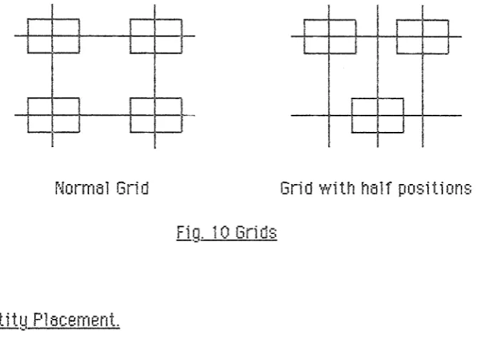
4.4 Grid Structures.
Due to 1 i rnitati ons i rnposed troth from the e~<terna 1 world and from the design methodology of the diagrarnmer the Entity boxes emd the
F.~elationship lines cannot tre placed just any\-vhere. Entity positions are
restricted trecause the direct p lacernent scheme for Re 1 at i onshi ps can cope only witr·I tbe Entities in predictable grid positions. To gi\.•e more
fle:x:ibility to the positions of Entities and to attempt to design a genereil
F~e i ati onshi p p 1 acement scheme v·tithout knowledge of any v·tork done e l sewt1ere \•voul d hsve rnsde the automst i c generation of di sgre~ms sufficientl!J cornplicste;j to tt~k:e it outside the scope of
em
Honours Project.The positions of Relationship corners and iine segrnents are limited
to positions on 11 grirj because of tr1e nature of ttle most often used .. and
most lirniterj .. output device -the line printer. The srnallest unit of size in
a diagr-am rnust be the same tiS, or larger tht~n, that of a line printer (U1e
printatr1e character). This means U1at artritrar-ily close Relationship lines
can oniy tte printed by o"(tiiOWing u~(' U!e diagram until trJe lines are one or
more cJ,aracter position apart on tl'"le l1 ne printer. Due to this .. and si nee 5
,jiagrt~m should take up sorne rninimum space, some lower lirnit to the
posit i ona1 ,ji ff erence tret ween Re 1 at i onshi p lines rnust be i rnposed - ttli s is a gri1j. ~~elationships are slso constrained to follow only horizonal and
vertical
1
i nes (r-'1t~nhattan1
ayout) si nee 5 printer carmot cope \'\''i U1 di a!~ona1
1 i nes.
Along with the grid defined for Entity plt~cernent (50 x 50) there v·tt~s also work done on a !~rid of 100 x 50. Tr1is grid t~llm>~ted Entities to t1e
deve 1 oped to t1 11 ow more freedom to Ent itt es but cret~ted too rnt~ny types of Re 1 tit i onshi ps for the direct Re 1 tit i on::Jti p p l ~Jcernent scheme too cope \"tith so it \·vas s~·te1ved ir11jefinitel~d- Also) this grid gt~ve no rea1 increase in the clarity of the diagrarns when used for Entity plticernent.
I I I
I
I
I
I
I
i
I
I
I
I
Normal Gri,j Grid ··NiUt half po:::itions
Fig. 1 0 Gri 1j:::
4.5 Entity P1 acernent.
The Entity placement algorithm in Sec. 3.3 is irnplernented in the
diagr-arnrner at page 3 of U"1e listing (Appendix E). There is only one point
worth reporting in regard to this section. As part of U1e attempt to make
the eutornati c diagram generator creete di agr-arns U"1at fu1fi 1 the eesthet i c
and i nf orrnati on expectations of users) a bi e::: on the relet i ve positions of
related Entities has t1een implernented as part of the distance function
t1et \·Yeen the Entities. Tt·Ji s t1i as function has seven:ll di H erent t1i as t!-!pes irnplernented .. whict·t are:
( 1) Ordi nar!d : the two Entities have no preferred relative
positioning_,
(2) SidebySide: they prefer to ht~".·'e the same
y
position)(3) Vertic:t~l : they prefer to have the same~< position .. an,j
(4) Upt~ndDown : one Entity prefers to be atrove the other but they don't cere whet re 1 t~t i ve hm-i zontt~l positions the!d
[image:30.595.116.460.160.399.2]These tliases at-e derived frorn various types of Relationships) and are
implemented tty ca1Jsing the distance function to return an artificially high
value (rnultipl!J the ordinary distance t1etween the two Entities tty some
large nurntter like 10) if the t'vvo Entities are not in the preferred relative
orientation. Tr·tere is no definite proof that the bias functions relate at an
to user e:x:pec:tations tnJt) since the current method of deterrnining
vvtlictt
Relationships tb!P8S cause which biases is pure 1 y ex peri mental.. user
feedback wi 11 refine the assurnpt ions used in the current i rnp 1 ementat ion.
4.6 Re lat i onshi p Placernent.
Re 1 at i onshi ps are p 1 t~ced on the di e~gram t1y a direct p 1 e~cernent scheme. These Re1ationsr·Jips are required, for the saice of nice looking
diagratr1s) to have as few crossings and corners as is possit,le. A way to
accornplist1 this is to place the Relationships in order of simplicity (this
order is given in Sec. 3.4) so that the relationships ¥tith the least nurntrer
of corners are placed first. As given in Sec. 3.4, each Rele~tionM·,;p is given
a type depending on the positions of the two Entities involved in the
Relationship. Each type of F:elationship has an area of the sides of the
bo~<es representing the Entities involved in a Relationship of that type
whi c:h are preferred 1 ocat ion::: for j oi ni ng the end::: of the Re 1 at i on~;hi p 1 i ne
to the Entity bo:x:es. These preferred areas i.\·vhi ch have not been shown here
due to reasons of space) have been chosen to minimise the chance of
ceusi nq crossi nqs ond the direct Re 1 at ~ ~ i onshi p rrl 1- acement routines choo::;e the point closest to the favourite position that is part of the preferred
en-eB and is not B 1 ready bei n!~ used.
For t!JPB 5 Relationships, if thet-e are more than one Relationship
tret ween the same two Entities the methods of choosing the points of
attacJ,n·,ent to the Entities cause unneccessary crossings. in this situation ..
the points of attachment on the uppermost Entity of these Relationships
For types 4 and 5 Relationships, there are hvo alternati'·le constructions of these Relationships (see Fig 12). To ensure that the most profitable alternative is finally placed, both of them are tested and the one v·thich causes the least crossings is retained. V·/hen each alternative is tested, the effects of Ute test construction must be tmdone before testing the ne::-::t or choosing the best (this includes U1e rearrangement of the points of attachment as described above).
1-
D
.---I
D
I
r--D
L
Fig 12. Alternative for tyQe 4& 5 RelationshiP-S
1.}'\:.,,~ ' M
l,._)
V1r1en the construction of a line runs into trouttle (as \·vt1en U1ere is no room 1 eft on U1e preferred section of an Entity box or in a gap ttet ween Entity t1oxes) U1e partial effects of the construction must tte removed. lf this happens, the Relationsrlip placement is attandoned and U1e k~elationsr1ip
[image:32.598.148.531.386.542.2]4.7 Line Printer Output.
'w'hen B diognnrr is finoil4 c:onstnJc:ted it must tre '•NTitten to e file to
·-be printed. A vi rtue!l i rna!~e of the di t~grarn is used on wt·1i cr1 diagram inforrnation is \·vritten in positions corresponding to EntHw and Relationship constructions. In this virtlJt~l imaqe, one horizonteil grid position is equivalent to three character positions and one vertical grid position to one character. Entit!d names are centered in the bm<es tbat repr-esent Entities and are split into more than one line according to their length (D:svs names are allowed up to 70 criaracters). The syrnttols used to represent i nf orrnat ion re!}:n-di
ng
the one/many/ opt i onel/marnjatory n~Jture of Relationship dep~Jrts from the conventions described in Sec. 2.3 (see Fig13) since it \·vas found to be too difficult to draw crows feet, etc on a line printer. Instead,
*
is used to represent many, and 0 and M are used to represent optional emd mandatory (they Cit-e pt-i nte1j inside the Entity t1ox ifU1ere
is
noroom
toprint H1ern on the
F~e1ationship
lin,.
r·1ultip1e
Relationsr·lips tll?.t\-veen hvo Entities are labelled \·vith a nurnt1er and a list of latrelled Relationship are printed belov·t the ,jiegrarn to enatrle them to be to 1 d apart.
_L
~Ifr-lv1
_f
R- En-anch- '
L
Fi!l 13. An E>~arnQle of Line Pr-inter Out~;11Jt
level (rnuch le::;s would have treen acr·1ie\1ed try the te6nination of this project if this 'Nets included). This is beceJuse these Reletionships ere required to adjecent for at least pert of Uteir length so thet information latrelling thern as these type of Relationst·lips can tre drav·m between them.
The printing of the die~gram cannot tre done by the obvious method of printing each rovv of the diagre~rn in its entirety and moving to the ne;,:t row, trecause of the fact U1e!t usefui information
on
U1e virtue!l irnagE: of the di eJgrarn may be (and usua 11y
'tti11 be) rnore characters ¥ti ,je H1an thev·tidth of the printer the diagram is intended for. n·1e method developed to print a diagram ii~~e this is to divide the diagram up into vertical strips the \"ti dth of the printer end print each of these in turn. These strips ere comtrined into a complete diagram try cutting and pasting them. The
5. F.~ e
s u
1tf!.
a
tl[.£1!11!.[~-Volor.ii,.
UR1:.::•ult§
The fee~tures 01" tile diagrarnrner envisaged at the beginning of thi::• pro
.i
ect thot have been i rnp 1 ernentE!d ore :t:m
eutornot i c Ent it!d Pl ocernent sc:herne, o ~~e 1 oti onshi p Pl ocernent scheme, ond the LinePrinter
Outputroutine. Although this is consi deratr 1
y
ttehi nd the scheclul e projected ot the beginning of the !dear, this is note
problern es this ::•chedule ~Ne::• drm·vn up tref ore otternpti ng to :::tudy emy of the prob 1 erns ossoci e~ted with grt:~prli c de::;i gn. A rno jor
a chi E!Vementis
the f t~ct that a autornat i c design systE!m sophisticated enough to tre accepted as pert ofn::svs
WB::; cornp 1 eted inAugust. This diagramming systern give the u::•en:• of
E:M:svs
the capt~bility to generate diagre~ms based on four dHferE!nt Entity selection schemes.As yet, tbere have been few ernpiricel results returnee! frorn u::•e of the di etgrC~rnrner but frorn wheit ht!s been returned the cone 1 usi on hets been re5ched thBt. for diagrams in'·lolving rnorE! that around 20 Entities the output produced turm; out to be very untidy and unhelpful with quite a f811V
RelBtionship lines not plC!ced. However~ the oppo::•ite ::•eems to be true for diagrams involving fewer than 20 Entitie::; with m,:cellent .. infonnative
dit~grt~ms being generated. This seerns to e~gree 1rl'ith the opinion that
die~gre~rn::; should be kept ets ::;rrwll o::• po::•:::ible ~Nith lorge Dt1to t·'todE!ls repreSE!nted in sorne rnanner by sevewe1l srna ll er di agra1r1~;.
2.,.:?.
lj rni t~t i C'.!)S.There E!Xist thr-ee lirrdtations to the diagramrnE!r in its current stt'Jte .. of ¥1'hich only bvo can be avoided. TheSE! lirnitations are mostly to do v·lith the grfd ::;tructures used in plBcing the Entitie:1s etnd F.~elotion::•hips that
rnake up a di egrarn.
The first lirnitotion, one that is not rernoveble but cen be virtut~lly
cornpletely ignured, i8 a lirnit on the number of Peletion:;:;hip:::o en Entit!d is
5ll01NE~d to be involved in. ~\ value for this limit (currently 32) rnust trr.:!
if this r,.•alue pro'·les to be too 101N it can tre reset to a higher value quickly
(Notice tht~t E~:svs defines
em
average of 4 Relt~tionships per Entity but in most mc11je l s there 1Ni l1 be some Entities Urt~t are related to far more thanthat rnt~ny).
The second l_!!~~__!lfnl is closely tied to the first t~nrj} 1ike\·Yise .. ct~n
virtually be ignored. This limitation is the definition of the number aruj
di stri but ion of the points at which t1 Re lat i onshi p 1i ne can be joined onto t~n Entity box. Tr1e current limit allo\·Vs 32 (as at,ove) of these points (9 on
both the top and bottom of an Entity box t~nd 7 on the left end right sides).
This 1it}'li1eJiJml~~~;.if_j_ttU~JOQ(e irnport~nce to the user then the first es
it can be the ct~use of the non-p1acement of sorne Re1t~tionships in larger
t1ode1s.
The third 1 imitation is ct~used by the coarse grid used for the
positions of Entities. This use of this grid rneans tht~t the spaces between
U1e Entities for the plt~cernent of Relationships t~re all of t11e same size.
Due to the ft~ets that ::;orne Entities ore more related than other_. ond
tt·1eref ore some oreos of the di ogrorn Y·till ht~ve more Re lati onshi p 1 i nes passing througt1 them .. some of these aree~s wi
11
become congested. Tt-,i slimitt~tion is ce~used by the design of the Entity e~nd Re1e~tionship placement
schemes and ~Nill ceuse some Relt~tionships in lt~rge t·1ode1s to become
unplact~trle. The only real solution to this limitation is to allow more
f1 exi t1il ity to Entity positions and to use an i nte 11 i gent gener-al
Re 1
t~t
ior~~i
p 1 i ne routing al gori trJtrLDue to the open-ende,j neture of the project and to the sr1eer size of
implementing all H1e aspects of the diegrarnmer_. there still remains much
untouched ¥tork to tre done. I rnportent sections of the pro j ec:te,j fi ni she1j diegrt~rnmer t~re ... :the interective dit~nrt~rn nenert~tor :j ::t / rnodifier. the 1oedinq . ._ and sa'·ling of diagrams, and the plotter output routine. A1thougr1 U1is work
structures has alreadu t1een done and \¥ill rnake this flJture work much ~· eBsier to implement.
The \..vork that remains to be done also includes modifications to
e~dsting work. Possibilities include preparing and irnplementing tr1e
algorithm mentioned in Sec. 3.3.5 and irnplementing the general Relationship router described in Sec. 3.4. Also_. the automatic p1acernent algorithms of the diagrammer have quite a few parameters (such as \·veighting schemes for Entitie::;_, Ure triasing of Entity positions (and the
pena1t~ for positions ¥thich violate these biases), and the method use,j to
determine the distance ttetween qrid positions for Entities). !t should t1e possible to improve U1e Butorrratic: generation of diagrams and to make U1e layout of diagrarns correspond more closely to user e~::pectations tty tuning
6. Cone 1 usi ons.
Tr1e main purpose
of
thisproject \·-ta::; to
write e1,jiagn:wnmer
forEXSVS_. \,·vith t10tf"! interactJ'...•e generation em,j modification
of
diagrat-rlsand
autorne;tic generation of diagrar·rr2;_ This ht~s tteen partially 5Chieve.d vtiH1
em
autornati c generator of di agran-,s suc:c:es::ofu11
y
i rnp 1 ernented. The size and complexity of the protdern of ,jesigning an t~utornatic generator 'Nos quiteune~~pecte1t Tt-,e gener-ator prcujuced as a result of this project .. as stt~ted in
the results_. seerns to t1e very useful for genertlting diagrems of 20 Entities or less as there is little intrinsic compler.:ity in Data 1"1cujels of Ulis size.
Ho\·Yever, some customers of Adata's en'·lisage Dt~ta Models involvin!~
up to 2C'O Entities end would like to use the diagrt~rnmer for docurnenting
their Model (if intended customers can not successfully use the
diagrammer then is it little more tht~n a toy for use at demonstrations of . '
D:svs·-rt
Clee~rly_. the euotrnatic generator in its current stete cannot dealreasonably with a Data Mode 1 of this size and cornp 1 exit~d
::w
U1e question must be esked - \hlhat needs to be done to successfu11 y use u-,e diegrarnmer-to gener-ate diagram for such 1 arge Data t1ode 1 s. There ewe
hvo
so 1 uti ons tothis si tuet ion em··i st~ged :
1. Write the interactive diagr-am gener-ator an1j imple'nrnent tbe ne\·V a 1 gori tt"trns for autornat i c generation.
Vlrite the i nterac:ti ve diagram !~ener-ator \'Yith hook:::; into the automatic generator for autorr1atically placement \h,·t1en require1t
The second a 1ternati ve 1 ooks more useful in the e~~trerne cases presente1j
l-11 re~l r·,·-it8 r·,i,-,dol~· ~~ 1·~ ~r•••.-·:::qoed +l-j·-·t +l-.o ••c·ot-l-.ij-rJ '""818(A +L·jo rt"it1·t•e,-. d•-;!
Li::~ .ij 1 L-''- l•.J <O· :::.. l t• 8 IV! ;:•u::~ . ll Cl ll k· IJ--•\:-1 . ;::. -I · .f. U '-'· C.1 _ I ··=• " be diagrammed t1y hand so Uwt the Data t'lode1 can t1e constructe,j out of
se·.,..era 1 srna 11 er ,ji agr-arns each of a managatd e size and each 1ji agrern of
clusters or groups of Entities es are recognisE~d try U1e user.
7. References.
[ 1] H. tt Bo~J8Qi3n, E. A as,
"An !ntegrtlted System for lntenKtive Editing of ScJ1ernatics, Logic Si rnul tit ion ornj PCB 1 ayout Design",
Proceedings of the i 5Ut Design Automation Conference .. 197Ei_. pg 1.
[2] P. Cormody, A. Barone_ .. J. f"1orell, A. 'Weiner-.. ._I_ Hennesy, "An lnteracti'-.··e Graphics System for Custom Design", Proc. 17th DAC, 1980_. pg 430.
[3J I. F.~. Dotres, "A Multi-contouring algorithm", Proc. 14th DAC .. 1977.
[4J L. Dysart_. M. Koifrnan, "An application of branch and ttound to autornat i c printed circuit board routing",
Proc 16th DAC} (1979), pg 494.
Published b~d Print t'iarketing Ltd. [6] C. J. Fisk, D. L. Caskey} L. L. \"'/est}
.. ACCEL : Automated circuit card etching 1 ayout", Proc. iEEE, v55 ( 1967), pg 197 L
[7} R. G. Gorside, T. A .. J. Nicholson,
"Perrnutat ion Procedure for the Eiackboard \···li ring Prob 1 em" .. FToc. lEE .. v115 (1968)_, pg 27.
[8] P. C. Gilmore_. "A :::olution to the module placement protrlern" .. Rep. RC430, IBtvt Vorktm"'tn Heights_. N.'Y.} 1961.
[9] C. H. Heider, "AnN-Step, 2-'v'ariatde Search Algorithm for the Component Pl ocernent Prob l ern"_,
Naval Research Logistics C!uarterly, v20 (1973), pg 699. ~e/
[ 1 0] Vol. Heyrv-;} Y.l. Sansen, H. Beke, i
"A line-Expansion A 1 gorithrn for the Genero1 Routing Prob 1 ern with o Guaranteed So 1 uti on",
[ 11
1
D. 'rl. Hightower_."A ~3olution to the Line-Routin!~ Protdem on the Continuous Pione", Pro
c.
6th DAC .. i 969 .. pg 1.[ 12] T. C. Koopmans_. r1. Beckman,
"Assignment Pr-oblem and the Locotion of Economic: Aetivities"_. Econometrico_. v25 ( 1957) .. pg 53.
[ t 3] E. L. Lo\·Yler, "The Quadratic Assignment Problem", t'1emagernent Sci._, v9 ( 1963), pg 586.
[ 14] C. V. Lee, "An Algorithtll for Patr1 Connection and its Applications"_.
IEEE
Transactions on electronic computers_. ( 1961t
p 346.[ i 5] ._!_ t'1artin E;, C. Finklestein_. "Information Engineering" 'v'olumes 1 & 2 ..
Put!lished by Savant Research Studies_.
2 Ne¥t Street, Ct~mforth, Lancashire.
[ 16] L. tvlory-Rauch, "Pin Assignment on 5 Printed Circuit Eioet-d" _.
P -ro'-:. < 1;:.1 11 C"tL· D . A ... L-. { 1" 07.-•) _.,o,_. pg 7 .-., .1... ..
[ 17] R. H ... J. t-'1. Otten, "Automatic Fl oorplan Design"_.
Proc 18th DAC .. ( 198 1), pg 261.
[ 18] G. Persk~d, C. Enger, D. t'l. Se1ove, "The Hughes Automated Layout System- Automated L~;l/\lLSI Layout Based on Channel Routing",
Proe. 18th DAC_. ( 19B 1
t
pg 22.[ 19] N. R.
Quinn_.
"The Placement Protdem as Vie'vved from the Phwsicsof Classical Mec:tlemics"_.
Pro c. 15th DAC, ( 1978), pg 173.
[20} C. F. Shupe_. "Automatic Component Placernent in tr1e Nomad System", Proc 15U"I D.A.C .. ( 1978)_. pg 162.
[211 ._!_Soukup, "Fast fvle~ze F.~outer",
Proc. 15th DAC .. ( 1978)_. pg i 00.
[22] l. Stei ntterg .. "The Bacf(troard \"li ring Protrl ern: A Placement A 1 gorithm", SlAt-'1 Review .. v3 .. 1961_.
pg
37.n
[23J T. Vo::Jli mura,
'lefl
Effi c:i ent Che~tme i F.~ outer",v
Pt-e c· -·-:;
1 -=·t c·,A' L-. { 1· 1::t.-'4)r,.,
-z.-.I .. L ._1_ • • • '· . _.Q , 1-l:-: ... .-'0.
[24] t'l Hanan, ,.J. t1. Kurtztrerg ..
"A Review of the Plocernent and Quodratic Assignment Protdem::;",
SIA~1 Review, v 14 .. 1972 .. pg 324.
[25] R. E. Eiurkard, K. Stratmann,
HOW TO GENERATE DATA MODEL DIAGRAMS
To obtain a diagram of part or all of your Data Model, enter the Model Listing facility of Data Modeling, choosing the option to
produce a listing of a Complete Data Model. There, you may take
option 2, a Diagram of the Model.
This will offer you a choice with which you effectively define the
scope of your diagram. You may obtain a diagram for
an Entity and its surrounding related Entities the Entities involved in a Procedure
the Entities in a Functional Area the complete Model.
Diagrams consist of boxes for Entities and lines from/to them for
Relationships. Currently there is a single restriction on the
size of Model which can be managed. The number of lines
entering/leaving a box is restricted to 9 at top and bottom and 7
on each side. This means that up to 32 Relationships can be
drawn to an Entity, although a few less may be a