The Modelling and Performance Analysis of User Interactions with a
Distributed System
Paul Ashton and John Penny Technical Report COSC06/90
1. INTRODUCTION
Measuring the interactive perfom1ance of a loosely-coupled distributed system is a difficult task. Work for a single user is spread across many computers, and there is no global time-base available for time-stamping event records. This report presents models which are the basis of an approach to measuring the interactive performance of loosely-coupled distributed systems.
The foundation of all of this work is a simple and general model of a loosely-coupled distributed, to be described in Section 2. We then describe in Section 3 a model of how a user interacts with such a distributed system, and how the processing involved in each user interaction can be represented as an interaction network. In section 4, some examples of interaction networks are given and discussed.
Much performance information can be gathered by analysing interaction networks. While no techniques for analysis are presented in this report, some of the ways in which interaction networks can be used for performance evaluation are described in [ASHT91]. For this report, the aim is to describe in detail our model of loosely-coupled distributed systems, our model of user interaction with such a distributed system, and the concept of an interaction network.
2. A MODEL OF LOOSELY-COUPLED DISTRIBUTED SYSTEMS A <;listributed system is a system .consisting of several autonomous components co-operating on a common task. The term distributed system is very general, and might be used in many different areas. Kleinrock [KLEI85] gives some examples from the natural world: ant colonies, schools of fish, and flocks of birds. Even within Computer Science, the term distributed system applies to a wide range of systems. A simple, general model of a loosely-coupled distributed computer system is described here. Then, our distributed system model is compared with various classes of, and · specific examples of, distributed operating systems.
2.1 The distributed system model
In Computer Science, the term distributed system usually refers to loosely-coupled systems. A loosely-coupled distributed system can be defined as:
A collection of separate computer systems (nodes) which communicate and synchronise only by passing messages across a communication network (paraphrased from [SILB88]).
threads of execution, each thread being "a schedulable unit of flow of control" [BRAN89]. Threads are the units of CPU scheduling, and can be created and terminated dynamically.
Threads may communicate through either of two mechanisms: by using shared
memory, or by message passing [ANDR83]. It follows from the definition above of a distributed system that shared-memory communication is possible only for intra-node communication. Message passing must be used for inter-node communication, and may be used for intra-node communication as well. Some systems provide
programmers with the shared memory abstraction for threads executing on different nodes [BAL89] [TAM90], but these systems use message passing to provide this abstraction.
Message passing allows threads to exchange data, as each message has associated data, and to synchronise their activities, as a message cannot be received before it has been sent. Areas of shared memory allow threads to exchange data, by writing values to and reading values from shared variables, but synchronisation is not directly supported. Several synchronisation algorithms, all of which need to use shared variables, have been developed [ANDR83]. In the following, "communicating through shared memory" is taken to include both data passing using shared variables, and synchronisation through techniques that use shared variables.
The model of a loosely-coupled distributed system can be summarised as follows: a system consists of nodes connected by a communication network. Threads execute on nodes, and communicate by passing messages and/or by using shared memory. The next section contains more detailed discussion of threads, message passing, and shared memory.
2.2 The model and distributed operating systems
Fortier [FORT88] identified three phases in the evolution of operating systems for distributed systems:
• early communication services • network operating systems • distributed operating systems
Early communication services provided users with logical machine names (rather than physical machine names), reliable communications, and services such as remote login, and file transfer.
Network operating systems evolved from early communication services. The same local (centralised) operating systems were used, but with an extra component, the network operating system layer, to make the communication network transparent to users and to the local operating system.
Distributed operating systems also provide network transparency, but have global, network-wide, policies for resource management. Network operating systems, because they are created by extending local operating systems, have only local policies for resource management.
The distributed system model presented here is general enough to apply to all of these types of operating system for distributed systems. The distinctions between the types of operating system discussed by Fortier and Tanenbaum are based on the services provided, the network transparency, and the resource management policies. Our distributed systems model covers all of the different types of operating system because all are implemented using threads that communicate using message passing and shared memory. Furthermore, a large distributed system may consist of several disjoint groups of nodes, where each group of nodes is under the control of a different operating system. The whole system may involve some combination of early communication services, network, and distributed operating systems. Our model applies to a distributed system containing several operating systems because each operating system is implemented by threads which communicate using shared memory and message passing.
Fortier classifies operating systems as being either process-oriented or object-oriented. The main elements of a process-oriented system are processes and messages. All actions are performed by processes, and processes pass messages when they need to communicate with other processes.
The basic structure in an object-oriented system is the object. An object is self contained, comprising both private data and a set of methods which can be invoked from outside the object, and which can manipulate the private data. Some existing systems fit well into one or other of these categories. Others are neither pure process-oriented systems nor pure object-process-oriented systems, but have most characteristics of one of these types of system. The dis~ussion of existing systems in Section 2.3 classifies existing systems as mainly process-oriented or mainly object-oriented.
Our distributed system model underlies both process-oriented and object-oriented operating systems. In both types of operating system, threads perform work, and communicate with each other using shared memory and message passing.
2.2 .I Threads
A thread executes within a context provided by the operating system, and the set of items which form the context for a thread are system-dependent. Items of context in most operating systems include the execution history of the thread, the saved processor state for the thread, the address space in which the thread executes, open objects
(including files and communication ports), scheduling information, and resource usage records and constraints [SILB88]. Some context must be associated with each thread-the execution history (usually a run-time execution stack), and thread-the saved processor state. Other items of context may be private to individual threads, or may be shared by two or more threads, depending on the nature of the operating system.
In process-oriented systems, a process is a thread of execution executing within a context. The address space of a process includes areas of executable code (sometimes called text), data, and run-time execution stack. The context of a process is usually "heavyweight", meaning that considerable overhead is involved in creating and
destroying a process context, or in context switching at the point of process exchange. The process address space is one item of the process context that can require a good deal of overhead to manage.
In many process-oriented systems, each process (and hence each address space) can contain only one thread of execution; this is the case for Unix [RITC74]. In such systems, thread creation, switching, and destruction are relatively expensive operations, as "heavyweight" contexts must be manipulated.
address space, and of switching between threads in the same address space. A cluster is a collection of threads that shares an address space. While "cluster" is not the only term used to describe a shared address space which can contain one or more threads, the term is used by Coulouris and Dollimore [COUL88], and for the Ameoba
distributed operating system [MULL86]. A process can then be defined as a special case of a cluster: a cluster that contains one, and only one, thread.
Clustering of threads introduces a 2-level process structure, with threads at the lower level, and clusters of threads at the higher level [TANE85]. In discussing Mach, Borghoff and Nast-Kolb [BORG89] describe threads as the entities of control, and tasks (clusters) as the entities of resource allocation. The components of process context are divided between the cluster level and the thread level. Each thread has a context which contains at least its execution history and saved processor state. Each cluster has a context which contains at least the address space itself, with the cluster providing a context for thread execution. Because all threads in a cluster share the same address space, and because nodes do not share memory, a cluster and all its threads must be on a single node at any given time.
Many applications might be performed by several communicating clusters, making it desirable to be able to deal with all of the clusters involved in a particular application. One way to do this is to add a further level to the process hierarchy, the process group. A process group is one or more clusters that are co-operating, and which we wish to treat as a single entity. Clusters within a process group may be on different nodes. The term "cluster group" may seem more appropriate, but the term "process group" is more widely used in the literature.
Several systems provide some type of process group construct. In Berkeley Unix, process groups are used by the shell to manage groups of related processes [LEFF88]. This management involves starting, suspending, killing, and allocating the terminal to the processes of a process group. In the V kernel [CHER85], operations which can be performed on a process group include sending a message to a process group (a
message is sent to all processes in the group), receiving a message from a process group (a message is received from any process in the group), killing all processes in the group, and sending a signal to all processes in the group. Liang et al [LIAN90] discuss using process groups to provide process group-wide communication primitives. One example is sending a message to a process group, which means that the message is sent to all processes in the process group.
In a process-oriented system, there can be a hierarchy of process constructs with from one to three levels though, often, there is only a single level hierarchy. Definitions of the various process constructs are summarised as follows:
Thread A flow of execution within an address space. The address space is provided by the cluster with which the thread is associated. Each thread has associated items of context, including at least the stack and saved processor state of the thread.
Cluster A collection of threads executing within an address space. Each cluster has items of context associated with it, one of which is always an address space. A cluster is located on a single node at any given time.
Process A cluster which contains one and only one thread. A process is usually regarded as a single entity rather than being divided into a thread part and a cluster part.
In object-oriented systems, threads are supported in either of two ways. One possibility is that all objects are passive, that is, they have no associated threads.
Threads are structured into processes and/or clusters and/or process groups in the same way that they are in process-oriented systems. An alternative approach is for some or all objects to be active. Active objects have thread(s) associated with them, and provide the context for those threads.
With passive objects, methods are usually perfmmed by the invoking thread for local invocations, and by agent threads in remote invocations. Methods of active objects may be performed in the same way that passive object invocations are performed, or they may be perfom1ed by one of the threads active within the invoked object.
In some object-oriented systems two or more threads can execute concurrently within an object. Eden [ALME85] is such a system. This is the equivalent of two or more threads executing concurrently or in parallel within a cluster in the process-oriented model.
Summary
Threads can be supported in many ways. In process-oriented systems, threads execute within processes or clusters, which may in turn be grouped into process groups. Object-oriented systems may use similar structures and/or may associate threads with active objects. The distributed system model presented in Section 2.1 holds for all of these different structures, as in all.of them the computation is done by threads. Only the structures within which the threads execute differ between the different systems. 2.2.2 Message Passing
Message passing, which occurs where one thread sends a message to another thread, can be used for both inter-node and intra-node communication. To send a message, some sort of address is required to identify the destination.
Communication by message passing occurs in both process-oriented and
object-oriented systems. In process-object-oriented systems, message passing is explicit and may be direct or indirect. In direct message passing, the sending thread specifies the thread it wishes to send the message to, and the message is sent directly to the receiving thread. In indirect message passing, the sending thread sends the message to a buffer called a mail-box. The message remains at the mail-box until a receiving thread requests a message from the mail-box. The message travels indirectly, via the mail-box, from the sending thread to the receiving thread [ANDR83].
In object-oriented systems, message passing is implicit. All object invocations can be regarded as comprising a pair of messages - a message from the invoking object to the invoked object when the object is invoked, and a reply message from the invoked object back to the invoking object when the invocation is complete. This type of message passing is equivalent to remote procedure call which is discussed further below. In practice, all inter-node and some intra-node invocations are done by passing messages; two threads are involved - a thread executing the invoking object, and a thread that executes the invoked object's method. Most intra-node invocations are performed in a very similar way to local procedure calls- a single thread calls and executes the invoked method.
copy of the message. If the message is to be received from a mailbox or a port then the mailbox or port to use must be specified to the receive operation.
Each of the send and receive operations may be blocking or non-blocking. A blocking send blocks the sending thread until the receiving thread receives the message. A non-blocking send delays the sending thread long enough to put the message into a buffer, although if no buffers are available the sending thread may be delayed. A blocking receive blocks the receiving thread until a message is available. A non-blocking receive checks to see if a message is available: if a message is available it is received, otherwise the non-blocking receive returns an indication that no message is currently available. The blocking send and receive operations together provide synchronous message passing, that is the sender and receiver synchronise with each other when the message is passed, and the non-blocking send and blocking receive operations together provide asynchronous message passing [BAL89].
Inter-node messages are passed by sending messages across the communications network. Intra-node messages may be passed in either of two ways. The message may be copied from the address space of the sending thread to the address space of the receiving thread, possibly via the kernel address space. An example is message passing using pipes or Unix domain sockets in 4.3 BSD Unix [LEFF88].
Alternatively, a message can be passed using an area of memory that is shared by the sending thread and the receiving thread. This method, used by Mach [YOUN87], can be much faster than copying for large messages.
Higher level protocols can be constructed using the send and receive operations, including remote procedure call (RPC), and Ada rendezvous. Broadcast or multi-cast send operations, which send a message to several destinations with a single send, may also be available. Remote Procedure Call (RPC) is a message passing protocol that is widely used in distributed systems [BIRR84], [COUL88]. As the name suggests, remote procedure call is a procedure call-like message passing protocol involving call message, return message pairs. RPC is common in distributed systems that follow the client/server model for providing a set of system services is in a distributed system. Common services include file, directory, and authentication service. Each service is provided by one or more server threads executing on one or more nodes. Each service provides a fixed set of procedures (the service interface) which users of the service (clients) can invoke using remote procedure calls. Ada rendezvous has very similar semantics to RPC [DOD83].
All of these different types of message passing involve passing messages containing data to a specified destination, and can therefore be represented by our distributed system model.
2.2.4 Shared memory
Communication using shared variables, also known as shared memory communication, occurs where the communicating threads can access a common set of variables. The shared variables are in an area of memory that is part of the address spaces of both threads. Communication occurs when one thread writes data to the shared memory, and this data is subsequently read by other threads. Shared memory communication can only occur within a node, as by definition nodes do not share memory.
monitors, and semaphores, need to use shared variables [DEIT84]. Synchronisation mechanisms are usually required to manage access to data structures in shared memory so that concunent update problems are avoided. System V Unix provides a shared memory facility, and also provides semaphores which processes can use to co-ordinate access to the shared memory [BACH86].
In process-oriented systems, shared memory communication can be performed by threads within a cluster, and by threads in different clusters if the shared memory area used for communication is common to the address spaces of both clusters. In object-oriented systems, threads which wish to communicate using shared memory can do so only via an object instance whose methods can be performed by the communicating threads.
Both shared memory communication, and synchronisation, are done in similar ways in process-oriented and object-oriented systems. Shared memory communication occurs through shared variables- variable sharing is more restricted in object-oriented
systems. Synchronisation is performed using semaphores and similar constructs, all of which are implemented using shared variables.
2.3 Examples of existing systems
Several existing process-oriented and object-oriented systems are discussed in this section. These systems conform to the general characteristics of process-oriented and object-oriented systems that were discussed in the previous section, where it was shown that the aspects of process· and object-oriented systems discussed could be represented by the distributed systems model. The systems discussed in this section can therefore be represented by the distributed systems model.
2.3 .1 Process-oriented systems (1) Berkeley Unix 4.3
Berkeley Unix (BSD) is an operating system for a single node (or centralised)
uniprocessor system. Berkeley Unix provides processes, with each process containing a single thread. Processes communicate using sockets, and, in a crude way, using signals. Both of these are forms of message passing. See [LEFF88] for further information.
(2) SunOS
SunOS is a Unix-based network operating system, originally derived from 4.2 BSD. SunOS provides processes, and supports lightweight processes (threads in our terminology) [SUN88a]. Most items of context are at the process (cluster in our terminology) level, with each lightweight process having few items of context- by default only a stack and saved processor state.
SunOS provides a variety of mechanisms for interprocess communication: sockets and signals (from Berkeley Unix), and messages (from Unix System V [BACH86]). The lightweight process library also provides its own message passing mechanisms. SunOS also includes Sun RPC, a remote procedure call implementation layered on top of sockets. Sun RPC is the basis for SunOS network services which are based on the client/server model [SUN88b].
(3) Ameoba
Ameoba is a distributed operating system developed at the Vrije University [MULL86]. Ameoba provides support for threads, with one or more tasks executing in the address space of a cluster. Mullender [MULL87] states that tasks have just a few items of context, without saying exactly what the items are.
Message passing is provided by the ability to' send messages to ports, with each port identified by a capability. Ameoba's message-passing protocol is RPC-like. Tasks within a cluster can communicate via shared memory, but clusters cannot share memory. In Ameoba 3.0 [TANE89], no explicit synchronisation mechanisms are provided. Tasks within a cluster are not pre-emptable and run until they are logically blocked, at which point another task in the cluster can begin executing. The protection of shared data structures relies on the data structures being in a consistent state
whenever a thread logically blocks. This method was found to be unsatisfactory and, in Ameoba 4.0, semaphore and mutual exclusion primitives are provided. Threads are no longer guarantied to run until they logically block.
Tanenbaum eta! [TANE89] describe Ameoba as an "object-based" system. Each server manages a collection of objects - for instance, the file server manages a collection of file objects. Each server, then, is an object manager, and is willing to perform a set of operations on the objects it manages. When a client uses RPC to call a server it provides the RPC layer with a capability, the operation it wants the server to perform, and parameters for the operation. The capability contains the port number of the server, an object number which identifies the object which the server operation is to use, and a rights field which specifies which operations the capability allows the capability holder to perform. Thus Ameoba is implemented in a process-oriented way, but operates in an object-based fashion. In fact the client/server model in general is an object-based model.
(4) Mach
Mach is a distributed operating system developed at Carnegie Mellon University [MAS087]. Mach supports threads, with one or more threads executing in the address space of a task (note the different usages of "task" in Mach and Ameoba). The task is an environment for threads to run in, and provides the threads with protected access to resources such as the address space, and capabilities for ports; that is, most of the items of context are associated with the task. Tevanian and Smith comment that the Unix process abstraction is simulated in Mach by combining a task and a single thread [TEVA89].
Message passing is done by sending messages to ports. Threads in the same task can communicate via their shared address space. Tasks may share memory. The Mach C threads library package provides machine-independent locking primitives for thread synchronisation.
(5) The V kernel
The V kernel is a distributed operating system developed at Stanford University
[CHER84]. It provides support for threads, with one or more processes executing in the address space of a team. The team concept originated in an earlier operating
system, Thoth [CHER79]. A Thoth process is a thread in our terminology, and a Thoth team is a cluster. When a process is created it is either created as part of the creating process's team, or as the first (root) process of a new team.
Processes in the same team can communicate using shared memory, but processes in different teams cannot share memory.
2.3 .2 Object-oriented systems (1) Clouds
Clouds is an object-oriented distributed operating system project at Georgia Tech [WILK89]. Threads execute within objects. When a thread is created it starts
executing at the entry point of an object. The address space of a thread consists of the object it is currently executing in plus some private stack space. When a thread invokes a local object, the object component of the address space of the thread is switched from the invoking object to the invoked object, and the thread executes the invoked method itself. When the invocation is completed, the object component of the address space of the thread is switched back to the invoking object. For invocations of remote objects, a remote procedure call mechanism is used. It is possible for several threads to execute within an object concurrently, or in parallel on a multi-processor node.
(2) Eden
Eden is an object-based distributed system developed at the University of Washington [ALME85]. The main structuring construct in Eden is the Eden object, or Eject. An Eject may be active or inactive. An active Eject has an address space and at least one thread executing within it. An inactive Eject is dormant and is saved on disc. Each thread is associated with a single Eject. Invocations are performed in an RPC-like way: a thread in the invoking Eject sends an invocation message; a thread in the invoked Eject receives the invocation message, performs the invoked method, then sends a reply message to the invoking thread; and, finally, the invoking thread receives the reply message. Messages are used in both local and remote invocations.
An Eject can have many threads executing within it, with the threads within an Eject synchronising using monitors.
(3) Emerald
Emerald is a "distributed object-based language and system" developed at the University of Washington [JUL88]. In Emerald, objects can be passive (without a process), or active (with a process). Every process in Emerald is associated with an active object. Object invocation is performed by the calling process. In remote
invocations the calling process migrates to the node where the invoked object is located, performs the invoked method, then migrates back to the node where the invoking object is located. Where the invoked object is remote, the invocation and the return from the invocation are passed as messages.
Multiple threads may be active in a single object, and synchronise using monitors. (4) ARTS
2.4 Summary
A model has been developed for loosely-coupled distributed systems. The model consists of a definition of the overall hardware architecture and a description of the software architecture. A brief description of the model is that:
A distributed system consists of a number of nodes communicating only via a communication network. Processors in each node execute threads. Threads communicate and synchronise using shared memory, and by message passing. The model is concise and general. It has been shown that the model describes very well a wide variety of operating systems for loosely-coupled distributed systems. The model is the basis for the development of the approach to measuring interactive
performance that will be introduced in the following Section.
3. A MODEL OF USER INTERACTION
The user of an interactive computer system conducts a dialogue with the system. The dialogue consists of one or more interactions, where each interaction consists of some input action by the user, and some processing and output reaction by the computer system. Because the interaction is the unit of dialogue in an interactive system, it is important to have an understanding of the nature of interactions if we are to measure the performance of interactive systems. A simple, general model of user interaction is presented,. based on the distributed systems model described earlier. Then we describe the interaction network, a way of describing the processing resulting from an
interaction.
The term interaction can have different meanings for different groups within
computing. The meaning of interaction to the computer performance community has been outlined above. To those interested in human factors and user interfaces, "interaction" is a much broader area, encompassing all issues relating to how humans interact with computers. Major concerns of the latter group include the representation, design, implementation, execution, evaluation, and maintenance of user interfaces [HART89]. Hereafter, the term interaction (or user interaction) will be used where the performance-oriented usage of interaction is intended, and the term human-computer interaction will be used where the broader human factors-oriented usage is intended. 3.1 A user interaction model
Most definitions of an interaction are along the following lines: the user inputs a request to the system, which processes the request, and then passes output from the request back to the user. The user then thinks for a period, before inputting their next request. This view of an interaction is prevalent in both measurement ([FERR83] and
[SHNE84], for example), and modelling ([HEID84] and [LEUN88], for example). Closely bound to the concept of an interaction is the idea of response time, an
important index for measuring the performance of interactive systems. Response time can be defined as the time taken for the system to process a user request [FERR83], although as noted in [PENN84] there is disagreement on exactly how response time should be measured.
User User Computer Computer
starts initiates begins completes
typing activity response response
I I I I
I I I I
[image:12.567.86.521.76.298.2]---(1)--l--(2)--l---(3)---~---l---(4)----l
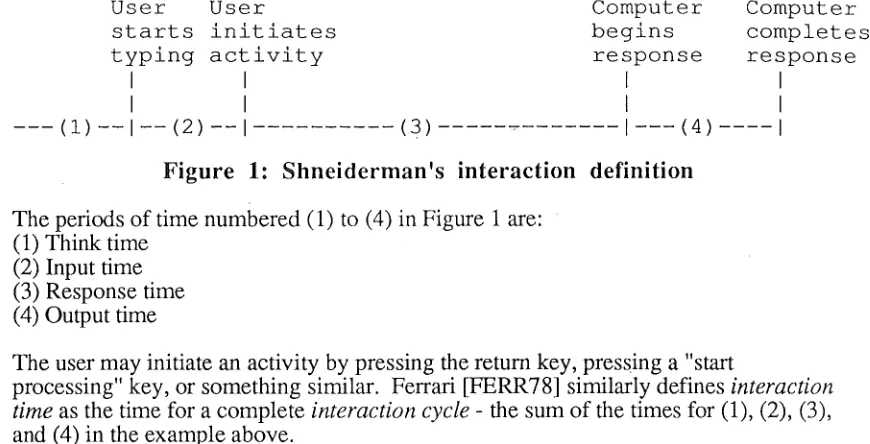
Figure 1: Shneiderman 's interaction definition
The periods of time numbered (1) to (4) in Figure 1 are: ( 1) Think time
(2) Input time (3) Response time (4) Output time
The user may initiate an activity by pressing the return key, pressing a "start
processing" key, or something similar. Ferrari [FERR78] similarly defines interaction time as the time for a complete interaction cycle- the sum of the times for (1), (2), (3), and ( 4) in the example above.
From this transaction-oriented view of user interactions, a definition of response time appeared to follow naturally. Abrams gave a widely-quoted definition of response time as the "elapsed time between the last user keystroke until the first meaningful character is displayed" [ABRA77], but individual response times have never been easy to measure. The "last user keystroke" of a command might usually be input of a newline character, but not every newline would signify the end of a command. The first output following that particular keystroke might be the beginning of the system's response, but might instead be a phrase such as "processing started". Also, a "response time of 10 seconds" for an interaction means little without specifying the amount of work in the interaction. Response ratio, the ratio of the measured response time to the time it would have taken without competition for resources, is a better index, but estimating the time that any interaction might have taken under "ideal conditions" is difficult [PENN84]. This transaction-oriented view of user interaction, or "sequential dialogue" [HART89], is not general enough to describe interactions with modern graphical user interfaces, which feature graphics as well as text, which allow mouse, touch-screen and voice input as well as keyboard input, and which allow the user to be in control of many interactions simultaneously [HART89].
Clearly, a more general model of user interaction is required, one that is both simple and general. The model given here is based on the idea that an interaction is an instance of the pair:
<user action, system reaction>
The action is the input of a·primitive information carrying unit, or lexeme [NIEL86], by the user, and the reaction is all of the processing (which may include output) resulting from the input of the lexeme.
A lexeme may be input by a key-stroke when input is from a keyboard, by a mouse movement or mouse button-up or -down event when input is from a mouse, and so on for other types of input, including touch-screen input, voice input, video input,
Defining an interaction in te1ms of the most primitive user actions gives two advantages over the command-line style definition of an interaction usually used in computer performance evaluation. First, it emphasises the fact that even for the simplest interactions there may be questions of performance. Foley and van Dam [FOLE82], for example, have discussed the costs involved for response times that are greater than user expectations. They also state that the time taken to respond to "reflex actions", such as typing a key or moving the cursor, should be less than 100 milliseconds, and that the time taken to respond to "simple" interactions should be no more than about 2 seconds.
The second advantage is that more complex <action, reaction> combinations can be defined in terms of primitive interactions, which allows a much greater range of user interface styles to be represented. Command-line style interfaces, using Shneiderman's [SHNE84] definition for example, can be defined as follows. Each character input on a command line is a lexeme, with an associated interaction. For a command requiring the input of n characters, the first n-1 interactions are trivial- usually just inserting a
character into an input buffer. The nth character, a newline for instance, initiates the command. The interaction associated with lexeme n includes all of (3) and (4) in Figure 1.
The model can also represent asynchronous dialogue [HART89], where the user can be involved in several tasks at any one time, and interactions may occur in parallel. Each interaction is still initiated by the input of a lexeme, but now system reactions can overlap. So for asynchronous dialogue, the set of interactions a user performs while logged into a system, the user's session; can be characterised by a set of overlapping interactions, each initiated by the input of a lexeme. For sequential dialogues, such as command-line interfaces, a user's session can be characterised by a set of
non-overlapping interactions, each initiated by the input of a lexeme.
Similarities exist between the <user action, system reaction> model of a user
interaction, and other models described in the literature. In van Renesse's functional processing model, each user input is the end of the current process and the start of a new one [RENE89]. Benbasat and Wand [BENB84] describe "a model for human-computer interaction" based on a command-line interaction style. Their model is "based on a dialogue being viewed as a sequence of basic interaction events", where "an interaction event is defined as an occurrence in the dialogue where the system awaits input from the user". The processing of an interaction event consists of prompt, input, action, and flow control (the selection of the next interaction event). They also state that "all processing that occurs between two interaction events is considered as the action of the first event". This model is very similar to our own, where the input is a user action, and the processing that occurs between two interaction events is the system reaction to the first event. The main difference is that our model is general, while their model is restricted to the command-line style of user interaction.
3.2 Interaction networks
Models have been described for a distributed system and for an interaction. A user interaction is defined to be a <user action, system reaction> pair. A user action is recognised by a single thread, which will perform some processing as a result of receiving the lexeme input by the user action. The processing performed by the receiving thread may include communication with other threads, which means that the. processing performed for a given user action may spread from the receiving thread to other threads, which may spread it to yet other threads, and so on.
represent the multi-thread nature of many system reactions, and can also record the various resources used during a system reaction. A graph representation for an interaction network is described, and related work is described. Examples of interaction network graphs are presented in Section 4.
3.2.1 Basic concepts and terminology
Each user action causes the system to perform a task, which is the system's reaction to the user action. A task is created when the system recognises a user action, for
example the system may detect a key-stroke. The recognition of the user action results in a thread doing some processing. This initial thread is likely to request other threads to perform processing by communicating with them. Thus the task starts in a single thread, and may spread via communication from there to many other threads. The task finishes at the time that the last remaining thread performing processing for the task completes that processing. Some threads which perform processing for a task may already exist, while others are created during the course of the task. Some threads that perform processing for a task may terminate during the task, while others (such as threads in a server) remain to perform processing for other tasks. At any point in time a user is supported by one or more tasks- one for each interaction they have initiated which is yet to complete.
A task, then, is performed by communicating threads. At any point in time I threads are performing work for a task, and J messages are associated with a task. Throughout the life of a task I+ J is always greater than 0. To provide a single framework for work done by threads and messages, and to highlight the different paths of execution in a task, the idea of a sub-task is introduced. Each task is carried out as one or more sub-tasks, where the steps in each sub-task are performed in a wholly sequential manner. At any instant in time, a sub-task is either associated with a thread performing work for the task, or with a message associated with the task (a sub-task can change between being message-related and thread-related). Now, I+ J is equal to the number of sub-tasks that exist, and so the number of sub-sub-tasks within a task is greater than 0
throughout the task.
When a user action is recognised, a sub-task is created to start performing the task. This sub-task is associated with the initial thread. As the task progresses, sub-tasks are created as needed, and each terminates when it has completed its part of the task. New sub-task(s) are created whenever an event occurs in an existing sub-task which results in two or more pieces of work for the task that proceed in parallel. These fork events include when a thread associated with a sub-task sends a message (the thread and the message are the two pieces of work), and when a thread associated with a sub-task creates a new thread (the creating and the created thread are the two pieces of work). A sub-task terminates when the thread it is associated with has completed its work for the task, or when it is merged with another sub-task in the same task. A task is finished-and the system reaction completed- when the last of its sub-tasks terminates.
3.2.2. Execution of a Task
The processing performed by the sub-tasks of a task can be represented by a graph called an interaction network. Each vertex of an interaction network represents an event in the life of a sub-task. An event occurs at an instant in time, so every vertex Vi
represents an event that occurred at time( vi). Each arc in an interaction network represents the state of a sub-task between two consecutive events (vertices). Another way of looking at this is to say that each arc represents the activities of a sub-task between two events of interest. Each arc is directed, and represents a forward
There are two main aims to consider when deciding on which events should be recorded in an interaction network. An interaction network should:
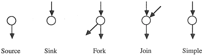
(i) Identify all processing performed for a task. This means that the interaction network must contain events that signify the beginning and the end of every sub-task. (ii) Record the occurrence of other, performance-relevant events which occur during a task. Examples of events that are likely to be of interest include the allocation of a processor to a sub-task's thread, and the beginning and the end of a disc request performed by a sub-task's thread. The set of performance-relevant events that it is possible to measure will vary between implementations, and the set of performance-relevant events recorded using an implementation will vary between experiments. Five patterns of arc connections to vertices are required to represent events, as shown in Figure 2. Source and fork vertices represent the creation of a new sub-task (the number of sub-tasks is increased by one), sink and join vertices represent the termination of a sub-task (the number of sub-tasks is decreased by one), and simple vertices represent the occurrence of other, performance-relevant, events (the number of sub-tasks is unchanged). Sub-task creation and termination, and simple events are discussed below.
Source Sink Fork Join Simple
Figure 2: Basic interaction network constructions
(1) Sub-task creation events. A sub-task can be created in one of two ways: (i) When a user action is recognised, causing a new task to begin. This event is represented by a source vertex, and there is only one source vertex in each interaction network. The outgoing arc represents a new sub-task associated with the initial thread. (ii) When a sub-task creates a new sub-task. This event is represented by a fork vertex, with the incoming arc and one of the outgoing arcs representing the existing sub-task, and the second outgoing arc representing the new sub-task. Such events most commonly occur when an existing thread creates a new thread, or when a thread sends a message. The new sub-task is associated respectively with the new thread or the new message. A "send event" may be a message send, a shared variable write, or a synchronization operation.
(2) Sub-task termination events. Analogously, a sub-task can end in one of two ways: (i) When a thread or message has completed the work it has to perform for the task. This event is represented by a sink vertex, with the incoming arc representing the sub-task associated with the thread or message which ends its work for the sub-task at the sink vertex.
[image:15.567.117.470.337.435.2]example, when two threads join or when one thread receives a message. In the latter case, the continuing sub-task is the one associated with the thread, and the terminating sub-task is the one associated with the message. A "receive event" may be a message receive, a shared variable read, or a synchronization operation.
(3) Other events. All other events do not affect the number of sub-tasks in existence, and are represented by simple vertices.
3.2.3 Relationship to the Distributed System Model
The model of a distributed system defined earlier was given in terms of nodes, threads and communication mechanisms (message passing, and shared memory). We now discuss how these constructs are represented in interaction networks.
(1) Nodes.
Each thread executes on a node. Therefore, node usage can be deduced from information associated with the threads used by a task. If a thread can migrate to another node part-way through its execution [SMIT88], each migration can be represented as a series of one or more vertices.
(2) Threads.
The relationship between threads and sub-tasks is analogous to that between processors and threads. A processor spends its time in the following loop - retrieve a thread from a queue, execute the thread until the thread is finished or blocks, then put the thread on a queue if it has blocked. A thread is in a similar sort of loop - retrieve a sub-task (by being created with the sub-task, or by receiving the sub-task with a message), execute work on behalf of the sub-task until either the sub-task is finished, or the sub-task is sent away with a message, then wait until the next sub-task is available
A thread is however different in that, while the number of processors is fixed, threads are created and destroyed dynamically. When a thread is created it has a sub-task associated with it. It then loops through the steps: execute sub-task
I
finish with sub-taskI
retrieve next sub-task. If a thread has an associated sub-task, the sub-task also tetminates when the thread terminates. The situation where a thread and sub-task are created together, execute together, then die together will be common. Threads which execute many different sub-tasks are common in software such as commandinterpreters and servers. Instances of both types of thread appear in the interaction network example in Section 4.
Situations exist where a sub-task is put into a queue by a thread for some period. For instance, a file server thread may act in the following way. A request message is received from a client asking that a file read by performed. The file server thread
schedules a disc read on behalf of the sub-task, and then performs processing on behalf of other requests until the disc read completes. During the period of the disc read the sub-task associated with the request is queued waiting for the file server thread to resume work on its behalf. This is a situation where the sub-task associated with the request receives two "time slices" from the thread, with a queueing period in between. One might think that to represent the queueing period requires a "queueing" sub-task state in addition to the message and thread sub-task states. Initially, a queued sub-task state was included in the model, but was found unnecessary because the queueing can be represented as the thread sending a message to itself.
• Beginning of association. A sub-task can become associated with a thread in one of two ways. First, when a thread is created it has a sub-task associated with it. This event is represented by a fork vertex if both creating and created threads perform work for the task (a new sub-task is created and is associated with the new thread), or a simple vertex where only the created thread performs work for the task (the sub-task switches from being associated with the creating thread to being associated with the created thread). Secondly when a thread not currently performing a sub-task of task A receives a message with an associated sub-task which is part of task A. This is
represented by a simple vertex which represents the reception of the message, and the sub-task switching from being associated with the message to being associated with the thread. Note that if the receiving thread is already associated with a sub-task of task A then a join vertex represents the reception of the message, and the receiving thread continues to be associated with the same sub-task.
Information on the identity of the thread, its execution context - the cluster, process or object it is executing in for example, and the node the thread is executing on, are among the things that can be recorded when the "beginning" of association event occurs. • Period of association. During the period that a sub-task is associated with a thread any events of interest related to the thread are recorded as events related to the sub-task. These events are represented by a series of fork (forking role), join (non-terminating role), and simple vertices as appropriate.
• End of association. The association between a thread and a sub-task ends in either a simple vertex or a sink vertex. Where the association ends in a simple vertex then, at the point that the thread has finished its processing for the sub-task, it sends a message, and the sub-task is transferred to the message. If there is no out-going message to transfer the sub-task to, then the end of the association is represented by a sink vertex, and is the end of the sub-task.
The creation of a thread is represented by a fork or a simple vertex, and the termination of a thread is represented by a simple or a sink vertex.
(3) Message passing
Message passing involves at least two events: the sending thread performs some send operation, and the receiving thread performs some receive operation. The message send is represented by a fork vertex if the sending sub-task continues to be associated with the sending thread after the send event, as a new sub-task is required to
accompany the message. If the sending sub-task does not continue to be associated with the sending thread after the send event, then the sending sub-task changes from being associated with the sending thread to being associated with the message, and the send event is represented by a simple vertex.
A message receive event is represented by a join vertex or a simple vertex. If the receiving thread is executing a sub-task that is part of the same task as the sub-task associated with the message, then the receive event is represented by a join vertex. The sub-task associated with the message terminates at the join vertex, and the sub-task associated with the receiving thread continues. If the receiving thread is not currently associated with the task of the message, then the sub-task associated with the message continues, and becomes associated with the receiving thread. This is represented by a simple vertex.
represented by simple vertices. If the message passes through several nodes, as it would in a store-and-forward network, and processing in the intermediate nodes is of interest, then there would be several events recording the progress of the message through the network.
In Section 2, both blocking and non-blocking variants of send and receive were
discussed. Also it is possible for a message to arrive before the receiver tries to receive it, or for the receiver to try to receive the message before a message has arrived. Thus there are 8 combinations of the three variables to be considered: send type (blocking or non-blocking), receive type (blocking or non-blocking) and what arrives first (message or receiver). Non-blocking receives are not considered further because:
(i) if a non-blocking receive is performed when a message has not yet arrived, then the thread that attempted the receive continues on without having received a message, and the non-blocking receive is represented by a simple vertex.
(ii) if a non-blocking receive is performed when a message has arrived, then the interaction network fragment to represent this is identical to the one for a blocking receive.
(a)
(c)
'
[image:18.567.90.507.295.704.2](b)
...
'
'' '
''
'(d)
(a) Blocking send, message arrives first. (b) Blocking send, receiver arrives first. (c) Non-blocking send, message arrives first. (d) Non-blocking send, receiver arrives first. (Blocking shown by dashed lines.)
Figure 3 shows the remaining four cases, the message send being represented in each case by vertex VI· In the figure, (a) and (b) show synchronous and (c) and (d)
asynchronous message passing.
(a) Blocking send, message arrives first. The message is sent at VI and the sending
thread is blocked. At v2 the message is received by the destination node, but the receiving thread is not ready. The time that the message spends waiting is represented by arc (v2,v3). The receiving thread performs a receive at v3, then sends an
unblocking message to the sending thread (arc (v4,v5)), and the sending thread is unblocked at vs.
(b) Blocking send, receiver arrives first. All vertices except v2 represent the same events as in (a). The receiving thread performs a blocking receive at v2, and remains blocked (arc (v2,v3)) until the message arrives and is received immediately at v3. (c) Non-blocking send, message arrives first. The message is sent at v1 and the
sending thread continues. The message arrives at its destination node at v2, but remains queued (arc (v2,v3)) until the receiving thread performs a receive at v3. (d) Non-blocking send, receiver arrives first. The message is sent at VI and the sending thread continues. The receiving thread performs a blocking receive at v2, and remains blocked (arc (v2,v3)) until the message arrives and is received immediately at
V3.
A broadcast or multi-cast send can be represented by a multi-way fork vertex, which has one outgoing arc for each thread that receives the message.
Higher level message passing protocols like remote procedure call, Ada rendezvous, and CSP message passing [ANDR83] are implemented using the basic message passing primitives, and can therefore be represented in an interaction network if the message passing primitives can be represented.
(4) Shared Variables and Synchronisation
There are two important differences between message passing communication mechanisms, and shared memory communication mechanisms:
(i) In message passing communication, messages carry data between threads and also synchronise threads, as a message cannot be received until after it has been sent. In shared memory communication, shared variables provide data transfer, but do not enforce synchronisation, so separate synchronisation primitives are required. (ii) Messages are transient, each message being "written" once by the sender, and "read" once by the receiver. Shared variables, on the other hand, can exist for much longer periods, and may be read and written many times. If a shared variable is written and then read more than once before the next write, then this is the very similar to broadcast communication in message passing, and can be represented in the same way. Difference (i) above means that the use of shared variables and the use of
synchronisation primitives must be treated separately. Difference (ii) means that determination of a task's boundaries is more difficult, as it may not be easy to
determine whether a shared variable write is a message send, or an update to a variable used to record status information.
variable write is represented by a fork or a simple vertex in the same way as a message send. A shared variable read is represented by a join or a simple vertex in the same way as a message receive. Because a shared variable .read always reads a value that is already available, shared memory communication is always of the form non-blocking send, message arrives first, as shown in Figure 3c. Vertex v1 is the write of the shared variable, and vertex v3 the read of the shared variable. Vertex v2 can be removed entirely, as "transmission" is instantaneous, so the message is available immediately. The length of time that the message spends queueing may be small, but is always non-zero.
A number of synchronisation primitives have been defined in the literature. All provide basically the same operations:
(i) wait, if necessary, until a shared resource is available. (ii) acquire the resource.
(iii) use the resource. (iv) release the resource.
In an interaction network, (ii) and (iv) above are events, and are therefore represented by vertices. The period of use, (iii), is represented by the sub graph (arcs and vertices) that connect the vertices representing (ii) and (iv). If the thread must wait for the resource, as in (i), then the beginning of the wait is an event, and is represented by a vertex which is connected to the vertex representing (ii) by an arc which represents the time spent waiting for the resource.
Synchronisation primitives are a means by which threads can communicate, albeit in a specialised fashion, and this communication should be represented in an interaction network. The relationship between a thread that releases a resource, and the next thread to acquire the resource, could be regarded as a message from the releasing thread to the acquiring thread, and represented in an interaction network as a message with a non-blocking send and a non-blocking receive.
Unlike messages, however, a release (the send equivalent) and the next acquire (the receive equivalent) are quite likely to occur in different tasks. The activities being synchronised may be otherwise independent of each other, and therefore from separate interactions. So, if both the releasing and acquiring sub-tasks are part of the same task, the release and acquire events are shown as message send and receive events. If the sub-tasks are parts of different tasks, then each event is represented by a simple vertex, with the release and acquire events in different interaction networks.
When the release and acquire are shown as a message, then the message has a non-blocking send, as a release need not wait for any sort of "acknowledgement" from the next acquire. Therefore Figures 3c and 3d can be used to represent the use of
synchronisation primitives. In both, vertex v1 is the release, and vertex v3 is the next acquire. In Figure 3c the release occurs before the acquire so the release "message" is blocked until the acquire occurs. In Figure 3d the acquire occurs before the release, so the acquirer must wait (arc (v2,v3)) until the resource is released.
3.3 The Interaction Network
The interaction network can now be considered as a whole. Each sub-task begins at either the source vertex (the initial sub-task), or a fork (forked role) vertex (all other sub-tasks), and progresses through a series of fork (forking role), join
An interaction network is a connected acyclic digraph D
=
(V, A), where V is the set of vertices and A the set of arcs in the digraph. An interaction network is a connected graph because all vertices in a sub-task are connected, all sub-tasks created after the first are either created directly by the first sub-task, or are created by one of itsdescendants, and each created sub-task is connected to the sub-task that created it. An interaction network is acyclic because each arc represents a forward progression of time, and a cycle would require at least one arc that went back in time, or at least two arcs which went neither forward nor back (sideways perhaps) in time.
The graph for an interaction network can be drawn in a systematic way. Assume that there are n vertices in the graph, vo, v1, ... , Vn-l· The function time(vi) gives the time at which the event represented by vertex Vi occurred. The initial vertex vo, the vertex corresponding to the recognition of the user action, is at the top of the page. Time flows down the page. For vertices Vi and Vj, i = 0 to n-1, j = 0 to n-1, then if i -:f. j, Vi is below Vj if time( vi) > time(vj), and Vi is above Vj if time( vi) < time(v~). It is assumed that time can be measured to such a precision that if i -:f. j then time( vi) -:f. time( Vj). The vertical distance between nodes need not be proportional to the time between the events represented by the nodes.
The sub-tasks of the interaction are listed across the top of the page. Each vertex is put underneath the name of the sub-task with which it is associated. The arcs that link successive vertices within a sub-task mean that the execution of a sub-task is represented by a line of vertices and arcs down the page. Arcs that represent
communication are links between these lines. An alternative arrangement is to list the threads involved in the interaction across the top of the page, and to put thread-related sub-task lines under the thread that executed the sub-task. This alternative is well suited to the common case where each sub-task is executed by only one thread, and is the layout used in the interaction networks in Figures 5, 6, and 7. Miller et al use the same layout for presenting Program Activity Graphs [MILL90]. PAGs, which have much in common with interaction networks, are discussed in Section 3.4.
The method of layout outlined above is based on the assumption that the events represented by the vertices in an interaction network can be totally ordered. If nodes are connected only by a communication network, determining a total ordering of events is difficult. A partial order [LAMP78] can always be determined, and the layout of an interaction network should at least reflect that partial order. A partial order is based on two things: first, that events within a node are totally ordered (because they are time stamped by the same clock), and second, a message cannot be received until after it has been sent (which helps to establish the order of events in different nodes). A close approximation of the total order can be achieved using a clock synchronisation algorithm [LAMP78] which synchronises the clocks of all of the nodes in the distributed system to within some maximum error bound.
3.4 Other Interaction Representations
Ferrari [FERR83] has given a very simple way of describing the processing involved in servicing an interaction. Ferrari's representation is a time-line showing various events in the processing of an interaction, including bursts of CPU and l/0 device activity, and the periods of queueing between bursts of activity. Because a single time line is used, all of the processing is done by a single logical thread, that is Ferrari's representation does not allow for parallelism or concurrency within an interaction.
request is performed by a single logical thread of execution. The thread's path through the monitor modules it executes can be shown graphically.
Yang and Miller describe program activity graphs (PAGs): a network representation for the processes and inter-process communication involved in the execution of a
distributed program [YANG88], [MILL90]. A PAG is an acyclic digraph, and is similar to an interaction network. The major use for PAGs is to compute the critical execution path for a program.
A PAG describes the execution of a distributed program. Vertices in a PAG
correspond to events, and arcs to activities. The main events recorded in a PAG are process creation and termination events, and message send and receive events.
Activities include all processing between events, which may include CPU processing, and device accesses. The PAGs described in [Y ANG88] weight arcs with the time taken to perform all of the processing associated with the arc, with queueing times resulting from contention for resources like CPUs and devices not included. Queueing times are excluded so that the results of the analysis of a PAG reflect the structure of a program. Yang and Miller note that queueing times could be included so that PAGs reflect the interactions and sc~eduling of the concurrent events in a program.
While our interaction networks are similar to Yang and Miller's program activity graphs, there are two important differences. The first is that program activity graphs are concerned with representing the processing of an entire program, whereas interaction networks are concerned with the processing of an interaction. Yang and Miller are interested in programs that are quite substantial in their resource usage, and are not interactive. This means that the programs that they are interested in monitming require no user input during their execution. There is a reasonable correspondence between the execution of a non-interactive program, and an interaction whose user action component is to request the execution of the same program.
Where programs are highly interactive, there is much less correspondence between interactions and programs. For instance, a user may ask the command interpreter to start up a full-screen editor. The interaction to start the editor, on a Unix system, consists of the processing done by the shell to start up the editor, and the processing done by the editor until it is set up, and able to process further input. The user will then have several interactions while using the editor, and then quit the editor. If interested in program performance, one would be interested in the execution of the entire editor program.
On the other hand, a single interaction can require processing from many programs, and may account for a part of a program's execution, rather than all of it. In the example to be given in Section 4, the interaction resulting from input of one newline character resulted in part of the execution of NCSA Tel net, telnetd, and csh, and all of the execution of date.
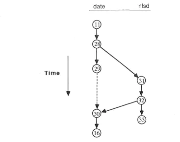
The second difference is that only processing performed by processes directly associated with the program is included in a program activity graph, whereas all processing (including that performed by servers) is included in an interaction network. Figure 7 in Section 4 shows how the processing performed by a file server can be included in an interaction network.
Most performance monitoring tools for distributed systems monitor program execution. The work described in the present report is significantly different in that it is
concentrated on monitoring interactions rather than programs. Existing program monitors are mainly used for monitoring non-interactive programs. Interaction monitors can monitor non-interactive programs, and they are also well suited to
4. EXAMPLES OF INTERACTION NETWORKS
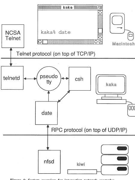
An example is now given of an interaction network. Consider a distributed system of three nodes: an Apple Macintosh, a discless Sun workstation (kaka) and a Sun
workstation with disc (kiwi). All are connected via ethemet. A single thread is executing the NCSA Telnet program, through which the user has initiated a login session on kaka.
NCSA
Tel net
kaka
kaka% date
Telnet protocol (on top of TCP/IP)
telnetd
csh
date
[Q
J
0
-lk~lk~
_l I
~
000
....____..
RPC protocol (on top of UDP/IP)
nfsd
[image:23.567.95.545.156.752.2]The login has initiated two Unix processes, telnetd and csh. The telnetd process is responsible for relaying inputs and outputs between NCSA Telnet on the Macintosh, and a pseudo-terminal on kaka containing input and output buffers. csh is a command interpreter which receives input from, and delivers output to, the pseudo-terminal. When the user types a character on the Mac keyboard, NCSA Telnet sends it across the LAN to the telnetd process which adds the character to the pseudo-terminal input buffer. csh subsequently reads the character from the pseudo-terminal.
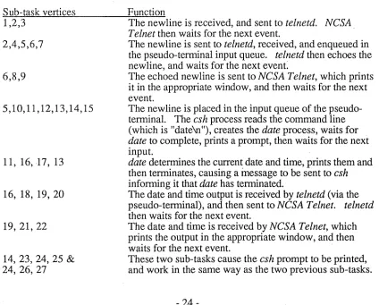
[image:24.567.89.513.457.798.2]Suppose that the user wishes to enter the Unix command date, which prints out date and time information. To do this, the user types 5 lexemes - 'd', 'a', 't', 'e', and newline. An overview of the distributed system and of the interaction is shown in Figure 4. In the figure date is shown communicating with nfsd on the file server kiwi. Such communication would occur if, for example, a page fault occurred during the execution of date, requiring date to request a page transfer from the file server kiwi, which would be performed by nfsd. In the example that follows it is assumed that no such file server requests are necessary, with file server accesses considered later in the section.
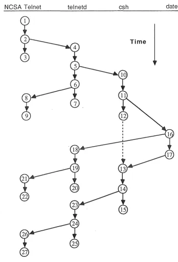
Figure 5 shows the interaction network for the system reaction to the user action of inputting the newline lexeme. The interaction networks for the 'd', 'a', 't', and 'e' lexemes all have the same form, that is, vertices 1 to 9 on Figure 5 and the arcs that connect them.
There are two nodes and four threads involved in the interaction network for the newline lexeme. One thread on the Macintosh is executing in NCSA Telnet, and three threads are on kaka, telnetd, csh, and date, each of them a Unix process. Remember that we are assuming that the execution date does not involve file server access. Only the 5 vertex types illustrated in Figure 2 are present in Figure 5. The sub-tasks can be easily identified. Fork and join vertices have two associated sub-tasks, all other vertices have one associated sub-task.
Sub-task vertices 1,2,3
2,4,5,6,7
6,8,9
5, 10,11, 12,13, 14,15
11, 16, 17, 13
16, 18, 19, 20
19,21,22
14, 23,24, 25
&
24, 26, 27Function
The newline is received, and sent to telnetd. NCSA Telnet then waits for the next event.
The newline is sent to telnetd, received, and enqueued in the pseudo-terminal input queue. telnetd then echoes the newline, and waits for the next event.
The echoed newline is sent to NCSA Telnet, which prints it in the appropriate window, and then waits for the next event.
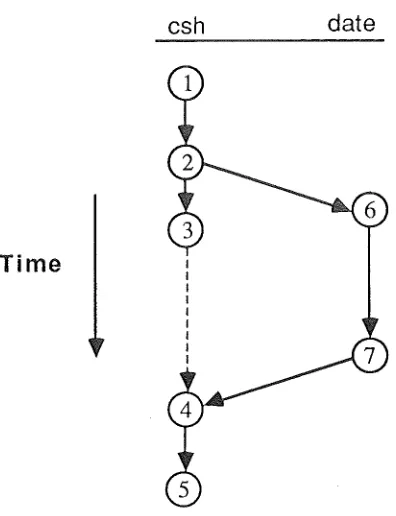
The newline is placed in the input queue of the pseudo-terminal. The csh process reads the command line (which is "date\n"), creates the date process, waits for date to complete, prints a prompt, then waits for the next input.
date determines the current date and time, prints them and then terminates, causing a inessage to be sent to csh informing it that date has terminated.
The date and time output is received by telnetd (via the pseudo-terminal), and then sent to NCSA Telnet. telnetd then waits for the next event.
The date and time is received by NCSA Telnet, which prints the output in the appropriate window, and then waits for the next event.
Each arc represents either computation or communication. Vertical arcs (and arc (v11,v16)) represent computation, while non-vertical arcs (except for arc (vu,VI6)) represent communication. (To achieve consistency, we could use a node vua to imply a virtual message from csh to date, but that would not accurately represent what SunOS does.)
NCSA Telnet telnetd csh date
Time
Figure 5: Interaction network for the newline lexeme
[image:25.568.128.476.157.668.2]