Resources Allocation and Failures in Step Topology under
Distributed Computing System
Taskeen Zaidi, Vipin Saxena
Department of Computer Science, Babasaheb Bhimrao Ambedkar University, Lucknow, India. Email: [email protected], [email protected]
Received October 5th, 2012; revised November 7th, 2012; accepted November 16th, 2012
ABSTRACT
In the past years, distributed computing is gaining the popularity due to reduction in execution time and low cost in-volvement. On the basis of this, Mobile Adhoc Network (MANET) is also increasing worldwide with major advantage that it has no involvement of wire and transfer of data can be done by the virtual paths if the existing path is congested. In the present work, MANET is considered in the form of step topology which consists of heterogeneous collection of the devices. The work demonstrates the resources allocation for execution of tasks and it consists of selection of right path if the link failures and by pass link failures. It also consists of the resource management over the new proposed step topology. Entire work is modeled with the help of well known modeling language known as Unified Modeling Language (UML) and model demonstrates the resources allocation for execution of the tasks.
Keywords: Distributed System; Link Failure; Step Topology; Resource Allocation; UML Model
1. Introduction
In the current scenario, many of the computing labs have been shifted from the centralized computing system to distributed computing system due to several advantages of distributed system. In the distributed system, commu- nication among the nodes called as devices is done by the message passing techniques for sharing of resources, data, etc. Let us first describe the research work available on the execution of tasks in the critical section under the distributed system. In the mutual exclusion, if one proc-ess is inside the critical section then no other procproc-ess or task is allowed to use the critical section. The mutual exclusion of tasks in distributed system are well ex-plained in [1]. Under the mutual exclusion, management of the resources is a very tough task for the operating system. In this connection configuration management, fault management, performance management, security management as well as management of resources are well explained in [2]. A well know reference Tanenbaum [3] has explained the conditions for mutual exclusion i.e. only one process can enter in critical section at a time and only that process utilize the resources other process is not allowed to use the resources. Hwang [4] has ex-plained the handling of tasks under distributed computing environment alongwith the data dependencies during the execution of the tasks. In [5], mutual exclusion of tasks are well described by Milenkovi.
Lamport [6] has described the time and ordering of
helpful for finding the global solution for network prob- lem.
In the present work a well known Unified Modeling Language (UML) is used to model the resources alloca- tion and many of the researchers have used this platform independent modeling language for the distributed com- puting system. First time, performance metrics for distri- buted and parallel applications using UML profiles has been suggested by Pllana and Fahringer [17,18]. A well known researcher H. Gomma [19] has used the UML in the various fields. The author has used the UML for dis- tributed, concurrent and real time application concepts of UML. The various aspects and versions of UML are well explained by the Object Management Group (OMG) and available in [20,21]. Recently, Saxena and Zaidi [22] have proposed a static topology for static interconnection of distributed systems by taking variations in cable seg- ments. Routing protocol for adhoc wireless network us- ing backpressure restoration has been propsed by Singh et al. [23]. Krunakaran and Thangaraj [24] proposed a cluster based congestion control protocol for mobile ad-hoc networks.
In the present work, a UML modeling is used for the resources allocation for the computer systems attached under the distributed environment for the MANET. The systems are arranged by a new kind of topology called as the step topology. Different kinds of the link failures are also observed for the step topology. The different tasks are executed inside the critical section by taking the resources but follow the concept of the mutual exclusion under distributed computing environment. The selection of the path is done with the help of dynamic source rout- ing protocol. UML class and sequence diagrams are also presented for the completion of execution of the process.
2. Background
2.1. Distributed System
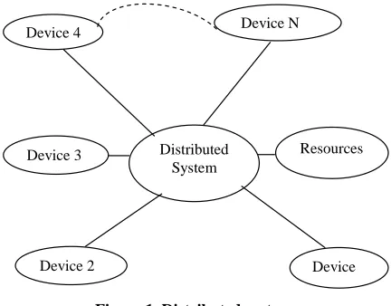
[image:2.595.315.531.86.255.2]Distributed system consists of multiple computers which are interconnected by message passing techniques. Each node connected in the network consists of process and local memory. The message passing technique allows point to point static connection among nodes. Distributed system provides resource sharing, improved performance and reliability and requires low installation cost. Com- munication is carried out by message passing among nodes are connected through the network. A sample diagram for the distributed network is shown below in
Figure 1.
In the above distributed network system, all devices along with resources are attached through the step topol- ogy. The devices may be Computer system, laptop, hand_held devices, mobile devices and resources are loaded on computer system.
Distributed System Device 4
Device 3
Device 2
Device N
Resources
Device
Figure 1. Distributed system.
2.2. Resources Allocation and Routing
Under distributed computing system resources can be shared by number of devices attached through the adhoc network represented in form of step topology. When the numbers of systems are connected around the globe then under distributed computing system they can share the resources which are flowing in adhoc network. The cate- gory of resources may be file sharing, data sharing, vid- eos sharing, audio sharing etc. In this system if we want to execute the task by taking the device which is allo- cated at a very far distance then by taking on remote the task can be executed on this device. This is called as the remote access of the devices and sharing of the resources of that device. Under the distributed system the device are shared as represented in the above figure.
From the complete step topology as defined in the [22], authors have taken a segment of five nodes as shown in
Figure 2. For each node a routing table is defined ac- cording to number of hops as represented in figure. The five nodes can share the resources according to path se- lection method. If any link failures then the desired node cannot share the resources for execution of a process. In the adhoc network the selection of path is based accord- ing to Dynamic Source Routing (DSR), which deter- mines the destination path according the virtual link if the middle link failures or congested in the distributed network.
3. DSR Path Selection Method
N
N1
N3 N4
N2 101 0 0
102 1 0 103 1 0
101 1 0 102 0 0 103 1 101 1 0
102 1 0 103 0 0 104 1 0 105 1 0
[image:3.595.130.516.85.476.2]103 1 0 104 0 0 105 1 0 103 1 0 104 1 0 105 0 0
Figure 2. Routing paths for step topology.
P1
P2
P3
P4
N1 N3 N5
N1 N2 N3 N5
N1 N3 N4 N5
N1 N2 N3 N4 N5
for transferring of the data. The different paths from source (N1) to destination (N5) are shown below in Fig-ure 3. The following types of failure may occur:
3.1. Link Failure
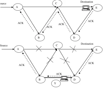
From the Figure 1, the five nodes are arranged for shar- ing of the resources and after execution of process ac- knowledgements are transferred to desired node. This is shown below in Figure 4. It is observed that when node C fails the primary path ACE is to be removed which shows that A cannot transmit data via link C. Then a vir-tual path is created by bypass method via route ABYDE which becomes the primary path to transmit the data as shown below in following Figure 4.
Figure 3. Path selection list.
In the network, the delay can also be computed as
Number of Packets Received Delay
Simulation Time
(2)
3.2. By Pass Link Failure
In this case if the bypass route BY in network fails then A cannot transmit data via link Y and ABYDE route does not come in existence then a virtual by pass link ADE comes in existence and the other route ABCE also comes in existence and then data is transferred to the destination device. This is shown below in the following
Figure 5.
4. UML Modeling for Resources Allocation
4.1 UML Class Diagram
A class diagram shows the static representation of the research problems in which the numbers of classes are arranged for interaction among them by using association, aggregation, inheritance, etc. A UML class model is de- signed for allocation of the resources and shown below in
Figure 6. As per Figure 2, the five computer systems are arranged in step topology and transferring the data from source node to destination node as per the path selection list represented in Figure 3. The UML class diagram represented in Figure 6 is designed for the N processors in general and it consists of nine UML classes namely Server, Thread, Process, CIN, Processor, Critical_Section, From the above Figures 4 and 5, the transfer of data
depends upon speed of the network measured as through- put which is the number of useful bits per unit of time. The delivery ratio is given by the following:
In the network, the delay can also be computed as
Number of Packets Received Delivery Ratio
Number of Packets Sent
Resources, Memory and Register. The process is distrib-uted by assigning threads through Thread class on MANET arranged in the form of step topology.
Multi-pleprocessors are connected and each processor has its own critical section represented as Critical_Section 1, Critical_Section 2, … Critical_Section N. At a time
ACK
ACK
ACK
ACK A
C
B D
E
Source Destination
ACK
ACK ACK
A
C
B D
E
Source Destination
[image:4.595.125.476.133.432.2]Y
Figure 4. Link failure in step topology.
ACK
ACK
ACK
ACK A
C
B D
E
Source Destination
ACK
Z ACK
A
C
B D
E
Source Destination
[image:4.595.120.478.135.724.2]Y
only one process can enter into the critical section and requesting for the grant of the resources handled by class name as Resources. After exexuting the task, the output is transferred to the Process via Memory and Register classes. In this interpretation the task/process may be treated as the subroutine, subprogram, macro, a segment of program for transferring of data.
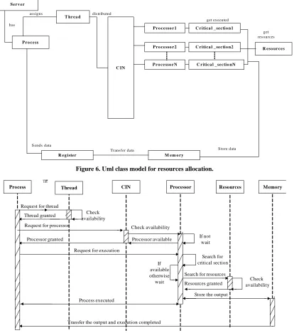
4.2. UML Sequence Diagram
A UML sequence diagram shows the dynamic behavior of the system and it shows the working of the system according to the clock of the device which is always
moving forward. The vertical lines shows the lifeline of the object which is represented at the top. The objects are initialized and after the use these are automatically de- stroyed in the dynamic modeling. The difference be- tween the end of the object and the start of the object is the lifeline of the object. The execution time of the proc- ess can be represented as the life line of the object as- signed to the process. From the literature, it is observed that many of the researches are using the UML sequence diagram for representing the dynamic aspects of the re-search problems, therefore, a UML sequence diagram is designed for allocation of the resources to the process as represented in Figure 7.
Se r v e r
P r o c e ss
T hr e a d
C IN
P r o c e sso r 1
P r o c e sso r 2
P r o c e sso r N
R e g iste r M e m o r y
R e so ur c e s C r itic a l _ se c tio n1
C r itic a l _ se c tio n2
C r itic a l _ se c tio nN
has
as s igns dis tributed
get res ources
S tore data Trans fer data
S ends data
[image:5.595.94.508.251.719.2]get executed
Figure 6. Uml class model for resources allocation.
Process Thread CIN Processor Resources Memory
憭?
Request for thread
Thread granted Check availability Request for processor
Processor granted
Check availability
Processor available
Search for critical section If
available otherwise
wait
Search for resources
Resources granted availabilityCheck
Store the output
Transfer the output and execution completed Process executed
Request for execution
If not wait
In the sequence diagram, a process object requests for the threads. If thread is available then it is to be assigned to the process and if not available, process will wait for thread assignment. When the thread is assigned it will send the request to the processors for assigning the criti- cal section which are attached under the distributed computing system. If processor is available then it will search for the critical section and as per the availability of critical section the process is executed after getting the resources from the resource object and finally the output data is transferred into the memory and the Memory ob- ject sends the output to the Process object. After the completion of execution the Process object is terminated. The entire working of dynamic modeling is shown be- low.
5. Conclusion and Future Work
From the above work, it is observed that UML is a pow-erful modeling language used to represent the static and dynamic behavior of the research problem. In the above, link failures in the MANET arranged in a new kind of step topology developed by the authors and procedure for resources allocations is described through the modeling. The present work can be extended by assigning the loads on the each node attached through step topology and speed of data transfer and delay in the packets can be measured. In place of MANET, step topology can be used for the static interconnection of the devices.
REFERENCES
[1] A. Siberschatz and P. B. Galvin, “Operating Systems Concepts,” 5th Edition, John Wiley and Sons, Inc., New York, 2008.
[2] B. A. Frouzen, “Data Communications and Networks,” Tata McGraw Hill, Noida, 2006.
[3] A. S. Tanenbaum, “Distributed Operating Systems,” Pren- tice Hall, Upper Saddle River, 1995.
[4] K. Hwang, “Advanced Computer Architecture,” McGraw- Hill Series in Computer Engineering Inc. Publishing, New York, 1993.
[5] M. Milenkovic, “Operating Systems: Concepts and De- sign,” Tata Mcgraw-Hill, Noida, 1997.
[6] L. Lamport, “Time, Clocks and Ordering of Events in a Distributed System,” Communications of ACM, Vol. 21, No. 7, 1978, pp. 558-565. doi:10.1145/359545.359563
[7] G. Ricart and A. Agrawala, “An Optimal Algorithm for Mutual Exclusion in Computer Networks,” Communica-
tions of the ACM, Vol. 24, No. 1, 1981, pp. 9-17.
doi:10.1145/358527.358537
[8] M. Maekawa, “A sqrt(n) Algorithm for Mutual Exclusion in Decentralized Systems,” ACM Transactions on Com-
puter Systems, Vol. 3, No. 2, 1985, pp. 145-159.
doi:10.1145/214438.214445
[9] H. L. Zhang, H. C. Leung and G. K. Raikundalia,
“Per-formance Analysis of Network Topologies in Agent Based Open Connectivity Architecture for DSS,” Google Search Engine, 2012.
[10] Y. Cheng and W. Zhuang, “Resource Allocation for Fast Handoff in Wireless Mobile Internet,” IEEE Communica-
tions Magazine, Vol. 40, No. 5, 2002, pp. 130-131.
doi:10.1109/35.1000224
[11] T. W. Chen and M. Gerla, “Global State Routing: A New Routing Scheme for Adhoc Wireless Networks,” IEEE
International Conference on Communications, Atlanta,
7-11 June 1998, pp. 171-175.
[12] D. B. Johnson and D. A. Maltz, “Dynamic Source Rout-ing in Adhoc Wireless Networks,” Journal of Mobile
Computing, Vol. 353, No. 6, 1996, pp. 153-181.
doi:10.1007/978-0-585-29603-6_5
[13] D. B. Johnson, D. Maltz and Y. Hu, “The Dynamic Source Routing Protocol(DSR) for Mobile Adhoc Net- works for IPv4,” IETF RFC 4728, 1996.
[14] S. R. Das, C. E Parkins and E. M Royer, “Performance Comparison of Two on Demand Routing Protocols for Adhoc Networks,” Proceedings of IEEE International
Workshop on Distributed Computing Systems, Mesa,16-
19 April 2001, pp. 425-432.
[15] D. Yu and H. Li, “A Model for Performance Analysis of Mobile Adhoc Networks,” Mobile Network and
Applica-tions, Vol. 6, No. 3, 2001.
[16] R. K. Ahuja, T. L. Magnanti and J. B. Orlin, “Network Flows: Theory, Algorithms and Applications,” Prentice Hall, Inc., Upper Saddle River, 1993.
[17] S. Pllana and T. Fahringer, “On Customizing the UML for Modeling Performance Oriented Applications,” Model
Engineering Concepts and Tools, Springer-Verlag,
Dres-den, 2002.
[18] S. Pllana and T. Fahringer, “UML Based Modeling of Per- formance Oriented Parallel and Distributed Applications,”
Winter Simulation Conference, Berlin, 19-21 June 2012.
[19] H. Gomma, “Designing Concurrent, Distributed, and Real-Time Applications with UML,” Proceedings of the
23rd International Conference on Software Engineering,
Toronto, 12-19 May 2001.
[20] OMG, “Unified Modeling Language Specification,” 2001. http://www.omg.org
[21] OMG, “Unified Modeling Language (UML): Version 1.5,” OMG Document Formal, Needham, 2003.
[22] V. Saxena and T. Zaidi, “Step Topology for Static Inter- connection of Computer Systems under Distributed En- vironment,” World Conference of Information Technol- ogy, Barcelona, 14-17 November 2012.
[23] R. Singh, A. K. Daniel and Z. Khan, “Position Based Routing for Adhoc Wireless Network Using Bandwidth Mananagement” International Conference on Emerging
Trends in Computer Science, Communication and
Infor-mation Technology, Department of Computer Science and
Technology, Nanded, 9-11 January 2010.
[24] S. Karanakaran and P. Thangraj, “A Cluster Based Con-gestion Control Protocol for Mobile Adhoc Networks,”
International Journal of Information Technology and