Abstract— Recent times have seen a tremendous surge of multimedia traffic over the Wireless Local Area Networks or WLANs. However, the bandwidth intensive multimedia traffic takes the most brunt when a WLAN is overloaded. Longer packet delay, jitter and lower throughput deteriorate the video quality significantly at the receiving end, thus diminishing the user experience. In this paper, we implement a new scheme to guarantee Quality of Service (QoS) for resource intensive traffic such as video even in times of resource scarcity in the network. We accomplish this by prioritizing certain (but not all) video packets and ensuring resource allocation to these packets over others. We also ensure that such preferential treatment to one class of traffic do not rob other low priority traffic of their fair share of resources. This scheme is implemented in the interface between the Logical Link Control (LLC) layer and the Media Access Control (MAC) layer of an 802.11 protocol stack. Extensive simulations over the NS-2 platform shows that our scheme leads to significant improvement in video quality at the receiver end while still retaining the QoS requirements for other traffic like audio and ftp, within acceptable bounds.
Index Terms—WLAN, 802.11, QoS, Multimedia.
I. INTRODUCTION
With the proliferation of PDAs and other wireless devices, wireless traffic is probably at an all time high [1]. Wireless Local Area Networks or WLANs are also experiencing their share of a fair amount of traffic growth. Concurrently, the use of multimedia application on wireless devices have also surged thus making multimedia traffic over WLANs a common phenomenon. However, it is the bandwidth intensive multimedia traffic that takes the most brunt when a WLAN is overloaded. Longer packet delay, jitter and lower throughput deteriorate the video quality significantly at the receiving end,
thus diminishing the user experience [2]. Extensive work has
been carried out on analysis of the bit rate variation of streaming video packets over WLAN networks and detailed study of their performance has been tabulated [3][4]. We ourselves have performed extensive experiments to study the performance of high bit rate streaming video streaming under variously congested wireless network conditions. Like [5], we concluded that received video looses its quality miserably under congested wireless networks. The results of our experiments also led us to conclude that the primary reason
Ramesh Goel is a greaduate student in the Computer Science Department at San Diego State University, San Diego, CA 92182, USA (phone: 858-218-5607; e-mail: goel_ramesh@ yahoo.com).
Mahasweta Sarkar is an Assistant Professor at the Electrical and Computer Engineering department at San Diego State University, San Diego, CA 92182, USA. (e-mail: [email protected]).
for this to happen was the loss of particular packets of the encoded video frames which play the most significant role in decoding the video stream. This led us to propose a novel scheme to enhance the QoS requirement and hence protect the quality of the video stream at the receiver’s end. Based on our prior study, we devised a scheme where we prioritize packets within a given video stream. We associate highest priority to those particular video packets that are crucial in the video decoding process and allocate preferential network resources to these preferred video packets thus protecting them from network calamities like packet loss and extensive delays. We also ascertain that we do not starve other traffic in the network.
Unlike most other work in the literature [5][6][7] that focus mainly on IEEE 802.11e-like mechanisms to enhance QoS in multimedia traffic, ours is independent of the underlying wireless technology. Also, the scope of these studies is limited solely to the 802.11 MAC sub layer while ours is not. In our work we focus a little higher in the 802.x stack and use the interface between IEEE 802.2 Logical Link Control (LLC) layer and IEEE 802.11 Medium Access Control (MAC) layer to make amendments to the protocol. This is particularly interesting because this makes our work portable across all kinds of low bandwidth MAC wireless protocols such as Bluetooth and ZigBee.
This work is particularly significant because available literatures and publications [6][7][8] do not talk about possible QoS implementations between the protocol layers. Interface queues between the protocol layers offers best effort service (FIFO) to all data packets and do not classify/categorize the type of packets passing through it. In this paper we do classify packets and provide priority to most significant video packets. Extensive simulation performed on the NS-2 platform, shows that the proposed scheme improves the quality of video streaming significantly while impacting other concurrent audio streaming and FTP traffic
insignificantly.
The rest of this paper is organized as follows: Section II discusses the basics of video compression and the 802.11 protocol stack respectively. Section III outlines the video QoS enhancing algorithm. Section IV discusses the simulation set up. Section V enumerates and analyses the simulation results. Finally, we conclude the paper in Section VI.
II. BASICS OF VIDEO COMPRESSION
Compression of multimedia content is necessary for transmission. While there are several compression methods available, the underlying common factor in all of them is that they require two algorithms: one for compressing the data at the source and another for decompressing it at the
Enhancing QoS for Streaming Video over
WLANs
destination. These algorithms are referred to as the encoding and decoding algorithms respectively. These algorithms have certain asymmetries. Usually a multimedia document will only be encoded once but will be decoded several times. This means that the encoding algorithm is allowed to be slow and require expensive hardware while the decoding algorithm must be fast and cheap. This, however, is not the case for all applications. For real-time multimedia, slow encoding is unacceptable [2]. A second asymmetry is that the encoding/decoding processes do not need to be invertible. It is usually acceptable to have the video signal after encoding and decoding to be slightly different than the original. When the decoded output is not exactly equal to the original input, the system is said to be lossy otherwise it is called lossless [2].
A. Video Coding Methodology
As mentioned in the previous section, all video compression methods are fundamentally based on the same model of encoding and decoding. In this section we will discuss the main concept behind MPEG video compression. The acronym MPEG stands for Moving Picture Expert Group, which worked to generate the specifications under ISO, the International Organization for Standardization and IEC, the International Electrotechnical Commission. Sequence of MPEG video comprises of three types of frames. These are: i) I-frames (Intra-coded): The term intra coding refers to the fact that the various lossless and lossy compression techniques are performed relative to information that is contained only within the current frame, and not relative to any other frame in the video sequence. In other words, no temporal processing is performed outside of the current picture or frame.
ii)
P-frames (Predictive):
Starting with an intra, or I frame, the encoder can forward predict a future frame. This is commonly referred to as a P frame, and it may also be predicted from other P frames, although only in a forward time manner. As an example, consider a group of pictures that lasts for 6 frames. In this case, the frame ordering is given as I,P,P,P,P,P,I,P,P,P,P,…Each P frame in this sequence is predicted from the frame immediately preceding it, whether it is an I frame or a P frame. As a reminder, I frames are coded spatially with no reference to any other frame in the sequence.iii)
B-frames (Bi-directional):
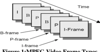
The encoder also has the option of using forward/backward interpolated prediction. These frames are commonly referred to as bi-directional interpolated prediction frames, or B frames for short. As an example of the usage of I, P, and B frames, consider a group of pictures that lasts for 6 frames, and is given as I,B,P,B,P,B,I,B,P,B,P,B,… As in the previous I & P only example, I frames are coded spatially only and the P frames are forward predicted based on previous I and P frames. The B frames however, are coded based on a forward prediction from a previous I or P frame, as well as a backward prediction from a succeeding I or P frame. As such, the example sequence is processed by the encoder such that the first B frame is predicted from the first I frame and first P frame, the second B frame is predicted from the second and third P frames, and the third B frame is predicted from the third P [image:2.595.345.509.312.397.2]frame and the first I frame of the next group of pictures. From this example, it can be seen that backward prediction requires that the future frames that are to be used for backward prediction be encoded and transmitted first, out of order. There is no defined limit to the number of consecutive B frames that may be used in a group of pictures, and of course the optimal number is application dependent. Most broadcast quality applications however, have tended to use two consecutive B frames (I,B,B,P,B,B,P,…) as the ideal trade-off between compression efficiency and video quality. The main advantage of the usage of B frames is coding efficiency. In most cases, B frames will result in less bits being coded overall. Quality can also be improved in the case of moving objects that reveal hidden areas within a video sequence. Backward prediction in this case allows the encoder to make more intelligent decisions on how to encode the video within these areas. Also, since B frames are not used to predict future frames, errors generated will not be propagated further within the sequence. Figure 1 shows an example of MPEG video frame sequence.
Figure 1:MPEG Video Frame Types
In general, neighboring pixels within an image tend to be highly correlated. As such, it is desired to use an invertible transform to concentrate randomness into fewer, decorrelated parameters. The Discrete Cosine Transform (DCT) has been shown to be near optimal for a large class of images in energy concentration and decorrelating. DCT is used to compress a single frame without reference to any other frame in a sequence. In addition, the temporal prediction technique used in MPEG video is known as motion estimation. The basic premise of motion estimation is that in most cases,
consecutive video frames will be similar except for changes induced by objects moving within the frames.
It is to be noted that I-frames need to be periodically distributed. If all frames depend on their predecessors for an accurate decoding, then any end-receiver that misses a frame (e.g. due to packet loss) could never decode any subsequent frames [2].
B. Video Quality Requirements
The most reliable mathematical metrics of video quality is the determination of Peak Signal to Noise Ratio popularly abbreviated as PSNR (expressed in decibel or db scale). PSNR is considered as the most objective
quantification of the quality of video transmissions over a network. Equations (1) and (2) illustrates the definitions of Mean Squared Error (MSE) and PSNR between source video frame I and received video frame K which has a size of mxn pixels and MAXi represents the maximum possible value of a pixel.
2
1 1
0 0
1
MSE ( , ) ( , )
m n
i j
I i j K i j mn
− −
= =
10
PSNR 20 log MAXi MSE
⎛ ⎞
= ⎜ ⎟
⎝ ⎠ (2)
For a 8 bit pixel, the value of MAXi would be 255. Typical
PSNR values for video compression lies between 30 dB to 50 dB with higher values preferred over lower ones.
Streaming video applications have more lenient QoS requirements than interactive video because they are more delay tolerant (the video can take several seconds to queue up) and are largely not jitter sensitive (because of application buffering). However, streaming video might contain valuable content, such as e-learning applications or multicast company meetings, in which case it requires service guarantees.
III. THE ALGORITHM
We now describe the algorithm that enhances QoS for streaming video over WLANs in detail. Recall that a typical 802.x protocol stack implementation has an “Interface Queue” between the protocol layers. This queue offers best effort service (First In First Out) to all packets. It does not classify/categorize the type of packets passing through it. Our scheme classifies incoming packets based on their “importance” and allocates separate resources for these packets. These packets also receive preferential treatment over other packets. Since we focus on QoS for streaming video applications, our packet prioritization is based on classifying certain video packets as more important than others. Recall, that amongst the three types of frames that are prevalent in a video source, the I-frames are the most crucial ones without which decoding of a video sequence at the receiver’s end will almost be impossible. Hence we prioritize these I-frames as “Most Valuable Video Packet” or MVVP. When a PDU arrives at the interface queue, its packet type is checked before en-queuing the packet. If the packet is a “Most Valuable Video Packet” then it is en-queued in a special queue called the “Video Friendly Queue” (VFQ) otherwise it is en-queued in the “Interface Queue” (IFQ). Overflow conditions are checked for both queues before a packet is en-queued. Whenever a packet needs to be sent to the MAC layer, de-queuing is performed first at VFQ and if there are no packets available at VFQ only then packets are de-queued from IFQ. Thus, special resource allocation and preferential treatment is given to MVVP. This ensures that regardless of the network condition (mainly congestion scenario) the MVVP gets the highest priority in terms of service which minimizes its delay. Also, packet loss due to buffer overflow is almost nullified as MVVP packets do not have to compete for buffer space with other packets. It is to be noted that the special buffer that we create for MVVPs do not require extra memory space. We split up the memory chunk that was designated for IFQ and allocate one-third of that memory chunk to VFQ. Thus the memory requirement is not increased but stays the same. We came up with the above ratio experimentally. It also is a function of the frequency of occurrence of I-frames in a video frame sequence such that overflow of VFQ is almost negligible. We discuss this in more detail in the next paragraph.
In addition, we claim that we do not starve packets belonging to other traffic types (be it audio, other video frames or ftp traffic) as well. This happens quite naturally
because going by the statistics of the frequency of I-frame occurrence in a video sequence, as outlined in Section 2, all encoded video streams have MVVP frames occurring periodically and not continuously. Thus, this algorithm does not choke IFQ. In practice, almost all video encoders use one I-frame every 9 to 15 frames. In our simulation, we use an I-frame after every 11 frames. This statistics takes care of the fact that the non-MVVP traffic is not starved as they too get their fair share of service.
Also, As mentioned in Section I, in our work we focus a little higher in the 802.x stack and use the interface between IEEE 802.2 Logical Link Control (LLC) layer and IEEE 802.11 Medium Access Control (MAC) layer to make amendments to the protocol. This is particularly interesting because this makes our work portable across all kinds of low bandwidth MAC wireless protocols such as Bluetooth and ZigBee and does not restrict it strictly to 802.11 networks alone.
IV. SIMULATION SET-UP
The network simulator that we used to simulate our protocol is NS-2 [10]. Unlike FTP and audio applications which can be simulated using built-in NS2 “agents”, there is no “agent” or “application” to simulate streaming video traffic directly in NS2. So to achieve simulation of the same, we had to take care of two things. First by using video codec and a set of tools we generated a video traffic file. Second, we created a new extension in NS2 to read this video traffic file and simulate video traffic over the network. The video format that we used in this experiment is the one that is most commonly used for video streaming applications with a resolution of 352x288 pixels. The video clip that we used comprised of 251 video frames.
We describe the entire setup as a three step process. The first step is to encode a raw video clip into an encoded video file and parse this file to produce an input traffic trace file to be used by NS2. The video clip that we used is a standard benchmark raw video clip. This clip contains 251 frames. The frame sequence that we chose for our simulation was of the following: IBBPBBPBBPBBI. For experiment purposes we have used H.264 codec to encode the video clip. The video encoder was configured to encode video frames in a “slice” of about 1000 bytes each. A “slice” is defined as the maximum chunk of encoded video data carried in a single packet which is transmitted over the network. The frame rate was set to 30 frames per second (fps) for encoding which is used in most high quality video streaming. These video slices (payload) are encapsulated into NS2’s “common header” before it is sent to the UDP protocol. NS2’s “common header” is used to simulate video streaming protocols such as RTP.
The second step of the process is to actually perform the simulation using the NS2 platform. Simulation is run through a “tcl” script. This script configures and creates various NS2 objects that are required to actually perform the simulation. The simulation involves transmitting and receiving packets comprising of streaming video, streaming audio and file transfer applications.
Comparison of “video send” and “video receive” files identifies the lost video packets if any. Finally, we use the decoder to generate viewable video contents. To quantify the quality of received video we calculate the PSNR of each video frame. In addition, in order to study the effect of our algorithm on concurrent FTP and Audio traffic, we also generate ftp and audio traffic in the simulation. This is achieved by generating trace files for audio and ftp traffic.
V. RESULTS AND THEIR ANALYSIS A. Streaming Video
To quantify the improvement that our algorithm produces on steaming video, we calculate the PSNR of each frame once before our algorithm has been implemented and once after our algorithm has been implemented. We plot ‘before’ and ‘after’ results in Figure 2. The ‘before’ plot shows the minimum PSNR of 20 dB while PSNR in after plot always stays above 36 dB. Also, fluctuation in PSNR before our algorithm’s implementation was huge and considered unacceptable video quality.
0 5 10 15 20 25 30 35 40
1 26 51 76 101 126 151 176 201 226 251
Frames
P
S
NR[
d
B]
before
after
Figure 2: Comparison of received video PSNR of each frame before and after our algorithm has been
implemented
Figure 3 shows screen shots of ‘before’ and ‘after’ received video frames. These frame pictures clearly show the
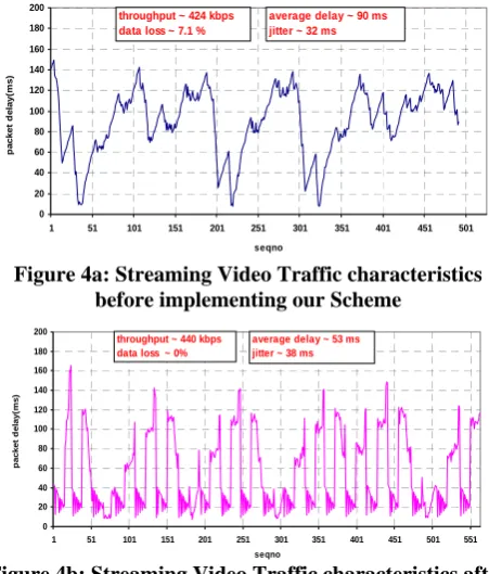
[image:4.595.312.538.57.322.2]improvement brought aboutby our proposed scheme.Figure 4a and 4b plot the video traffic characteristics obtained from captured trace log for video traffic ‘before’ and ‘after’ our proposed scheme had been implemented. Throughput, delay, jitter and packet loss statistics are also calculated and labeled on the plots. Jitter is calculated as the square root of variance in delay.
Figure 3: Screen shots of “before” and “after” received video frames
0 20 40 60 80 100 120 140 160 180 200
1 51 101 151 201 251 301 351 401 451 501
seqno
p
a
cket
d
e
lay(
m
s)
throughput ~ 424 kbps data loss ~ 7.1 %
average delay ~ 90 ms jitter ~ 32 ms
Figure 4a: Streaming Video Traffic characteristics before implementing our Scheme
0 20 40 60 80 100 120 140 160 180 200
1 51 101 151 201 251 301 351 401 451 501 551
seqno
p
acket
d
el
ay
(m
s)
throughput ~ 440 kbps data loss ~ 0%
[image:4.595.60.280.311.431.2]average delay ~ 53 ms jitter ~ 38 ms
Figure 4b: Streaming Video Traffic characteristics after implementing our Scheme
B. Streaming Audio
Before’ and ‘after’ audio traffic characteristics are also plotted to study the effect of our proposed scheme on streaming audio traffic. Comparing the Figures 5a and 5b shows that there are no major changes in traffic
characteristics other than 20ms increase in peak delay and 7ms increase in jitter after our scheme has been implemented. However, both these variations are well within audio QoS limits. It should also be noted that the average delay of the streaming audio packets have been lowered by 10 ms after our scheme has been implemented.
0 20 40 60 80 100 120 140 160 180 200
1 201 401 601 801 1001 1201 1401 1601 1801 2001 2201 seqno
pa
c
k
e
t de
la
y
(ms
)
throughput ~ 951.5 kbps data loss ~ 1.04 %
average delay ~ 87.5 ms jitter ~ 33 ms
Figure 5a: Streaming Audio Traffic characteristics before implementing our Scheme
0 20 40 60 80 100 120 140 160 180 200
1 201 401 601 801 1001 1201 1401 1601 1801 2001 2201
seqno
p
ack
et
d
e
lay(
m
s
)
throughput ~ 946.5 kbps data loss ~ 1.04 %
[image:4.595.312.536.493.731.2]average delay ~ 77.5 ms jitter ~ 40 ms
Figure 5b: Streaming Audio Traffic characteristics after implementing our Scheme
C. FTP Traffic
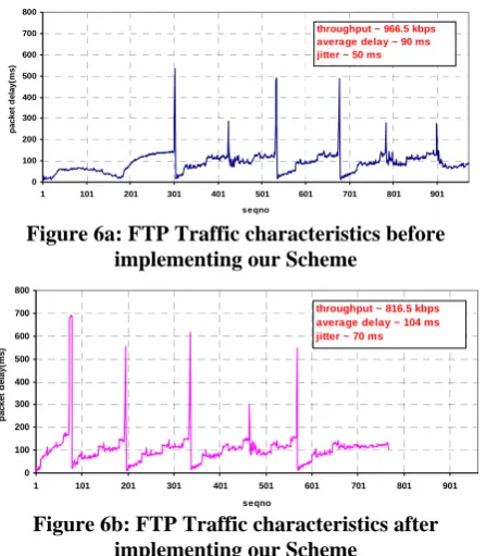
[image:4.595.53.276.570.693.2]been implemented are reported in Figure 6a and 6b respectively. FTP throughput is reduced by about 150 kbps and there is also an increase in packet delay. However, the brunt in performance is encountered only when a video streaming is in progress concurrently.
0 100 200 300 400 500 600 700 800
1 101 201 301 401 501 601 701 801 901
se qno
p
acket
d
elay(
m
s)
[image:5.595.60.284.115.371.2]throughput ~ 966.5 kbps average delay ~ 90 ms jitter ~ 50 ms
Figure 6a: FTP Traffic characteristics before implementing our Scheme
0 100 200 300 400 500 600 700 800
1 101 201 301 401 501 601 701 801 901
seqno
p
a
c
ket
d
e
lay(
m
s
)
throughput ~ 816.5 kbps average delay ~ 104 ms jitter ~ 70 ms
Figure 6b: FTP Traffic characteristics after implementing our Scheme
D. Analysis
The simulation results presented above are summarized in Table 1 and discussed in this section. For streaming video applications our proposed scheme significantly improves visual video quality as showcased in Figure 3. PSNR values of received video frames are significantly higher than before. Our work increases the video data throughput by about 3.75%. Average delay of video traffic is decreased by 40%. And packet loss is decreased by 7%.However jitter is increased by 18.75%. In the case of concurrent audio streaming, there is no significant adverse effect on audio traffic characteristics. Drop rate of audio packets remains same as before our implementation. There is a slight increase in the delay and jitter of audio packets but those are well within the QoS requirements limits. Audio traffic throughput loss is 0.5% which is practically unperceivable by the human ear. An increase in audio traffic jitter by 21% would mean an increased playback buffer at the receiver.
In case of FTP traffic, data throughput has reduced by 15%. It can be argued that this is an acceptable price to pay for significantly improved streaming video reception. More so, when we take into account the fact that such degradation in FTP traffic throughput occurs ONLY when there is a simultaneous streaming video transmission going on in the network. Otherwise, the FTP traffic retains its enhanced performance.
There are a few more interesting conclusions on the over all traffic characteristics. There is a net gain of 7% for packet transfers in WLAN network. However there is an over all network throughput loss of about 6%. This can be explained because of over all increase in network jitter by 29%. Contrary to network jitter, average delay for the network
[image:5.595.298.526.175.275.2]decreased by 12%.Parameters listed in columns of Table 1 denote traffic characteristics of streaming video (VDO), streaming audio (ADO) and ftp traffic types before (B) and after (A) our algorithm had been implemented. The traffic characteristics tabulated in Table 1 comprise of connection throughput or actual data transfer rate, percentage of data lost during transmission over a wireless link, average delay from source to destination and delay variations (Jitter) between source and destination.
Table 1: Traffic Characteristics Before (B) and After (A) Algorithm Implementation
Traffi c
Thruput (KBps)
Data Loss (%)
Avg.Dela y (ms)
Jitter (ms)
B A B A B A B A
VDO 424 440 7.1 ~ 0 90 53 32 38 ADO 952 947 1 1 88 78 33 40 FTP 967 817 NA NA 90 104 50 70
VI. CONCLUSION
Multimedia traffic over Wireless Local Area Networks has seen tremendous proliferation in the recent past. However, today’s technology is yet to catch up on providing the QoS that is required to support the bandwidth intensive multimedia traffic especially when the network is congested. In this paper, we implement a new scheme to guarantee Quality of Service (QoS) for resource intensive traffic such as streaming video even in times of resource scarcity in the network. We accomplish this by first studying the characteristics of video packets and understanding that certain video packets are more crucial to the decoder in being able to decode the video frame sequence. We prioritize these video packets, allocate separate network resources for these packets and ensure that these packets receive preferential service over other packets in the network. We perform extensive simulation over the NS-2 network simulation platform to study the effect of our algorithm on streaming video application over WLANs. We also study the impact of our algorithm on concurrent traffic like streaming audio and ftp traffic. Simulation results show that our algorithm decreases streaming video packet delay by 40ms and reduces packet loss by 7% while increasing throughput of the same by almost 20Kbps. In addition, our algorithm has no significant negative impact on other concurrent traffic like streaming audio.
ACKNOWLEDGMENT
We thank Dr. Kris Stewart at the Computer Science Department at San Diego State University for her very valuable counseling and guidance on this work.
REFERENCES
[1] Chih-Heng Ke, Ce-Kuen Shieh, Wen-Shyang Hwang, A. Ziviani, “Improving Video Transmission over the Internet”, IEEE Potentials Magazine Feb 2007.
[3] M. Van der Schaar and S. Shankar N, "Cross-layer wireless multimedia transmission: challenges, principles, and new paradigms," IEEE Wireless Communications, vol. 12, no. 4, pp. 50-58, 2005.
[4] G.-M. Su and M. Wu, "Efficient bandwidth resource allocation for low-delay Multiuser Video Streaming," IEEE Transactions on Circuits and Systems for Video Technology, vol. 15, no. 9, pp. 1124-1137, 2005. [5] Guijin Wang, S Futemma, M.Kawada, E.Itakura, “Practical rate
control for video over WLAN” IEEE Consumer Communications and Networking Conference (CCNC), Las Vegas, Nevada, Jan. 2006 [6] H.M Liang, et. al, “Performance Evaluation of 802.11e EDCF in
Infrastructure Mode with Real Audio/Video Traffic” Proceedings of ACM The International Conference on Networking and Services,May 2006.
[7] M. Lu, P. Steenkiste, and T. Chen, "Time-aware Opportunistic Relay for Video Streaming over WLANs," IEEE International Conference on Multimedia and Expo (ICME), Beijing, China, July 2007. [8] Z.N. Kong, D. H. K. Tsang, B. Bensaou, Gao Deyun, “Performance
Analysis of IEEE 802.11e Contention based Channel Access” IEEE Journal on Selected Areas of Communication, Dec 2004.
[9] “IEEE Standard Information Technology – Part 11: Wireless LAN Medium Access Control (MAC) and Physical Layer (PHY) Specifications (IEEE Std 802.11-1999)”, IEEE Inc June 2003. [10] Kevin Fall, Kannan Varadhan, “The ns Manual”, The VINT Project,