ISSN Online: 2331-4249 ISSN Print: 2331-4222
DOI: 10.4236/wjet.2019.74046 Nov. 15, 2019 634 World Journal of Engineering and Technology
Development of a Microcontroller Based DC
Motor Speed Control System
O. O. Adejumo1*, W. A. Azeez2
1Department of Physics and Solar Energy, Bowen University, Iwo, Nigeria 2Department of Physics, The Polytechnic, Ibadan, Nigeria
Abstract
This work reports the development of a microcontroller based control system to change the speed of a DC motor. Pulse Width Modulation (PWM) tech-nique was used to control the amount of power delivered to the load (the DC motor) without dissipating any wasted power. The components and assembly of this microcontroller circuit are highlighted in this paper, and the con-structed circuit tested. This device was used to control the speed of a rotating fan attached to a DC motor. The DC motor speed variations were read from a Tachometer connected to this motor and the results obtained show good agreement with our expectations. DC Motor speed microcontroller devices find applications in many areas of life, and its applications in small scale in-dustrial settings will no doubt enhance the quest for development in a devel-oping nation like ours.
Keywords
Microcontroller, DC Motor, Pulse Width Modulation, Circuit, Rotor
1. Introduction
Direct current (DC) motors find useful applications in many control systems [1]. DC motor speed control is about the change of the drive speed of the motor to a value required to perform a work process [2]. DC motors are made up of two basic parts namely the stator, which is the stationary part and the rotor, the in-ner rotating part, usually called the armature. The rotational speed of a DC mo-tor depends on the interaction between the two magnetic fields set up by the stator’s stationary permanent magnets and the armature’s rotating electromag-nets. By controlling this interaction, we can control the speed of rotation of the DC motor [3]. This speed control can be achieved in many different ways. A
How to cite this paper: Adejumo, O.O. and Azeez, W.A. (2019) Development of a Microcontroller Based DC Motor Speed Control System. World Journal of Engi-neering and Technology, 7, 634-639.
https://doi.org/10.4236/wjet.2019.74046
Received: August 26, 2019 Accepted: November 12, 2019 Published: November 15, 2019
Copyright © 2019 by author(s) and Scientific Research Publishing Inc. This work is licensed under the Creative Commons Attribution International License (CC BY 4.0).
http://creativecommons.org/licenses/by/4.0/
DOI: 10.4236/wjet.2019.74046 635 World Journal of Engineering and Technology simple and easy method is the use of pulse width modulation, PWM technique, which can be achieved by driving the DC motor with a number of “on” and “off” pulses and varying the duty cycle of the pulses while the frequency is kept con-stant [4]. Changing or modulating the timing of these pulses, controls the speed of the motor, i.e., the longer the pulse is “on”, the faster the motor will rotate and the shorter the pulse is “on”, the slower the motor will rotate. Hence, the wider the pulse width, the more average voltage applied to the motor terminals, the stronger the magnetic flux inside the armature windings and the faster the mo-tor will rotate. This way, the voltage across the terminals of the momo-tor can be regulated, and, hence the power applied to the motor can be controlled. In cases “switching on” and “switching off” are done in quick succession, the motor ro-tates at a slower speed between zero and full rated speed [5]. This is what a PWM technique based controller does: it switches the motor “on” and “off” with a pulse train. When the motor is “on” for a short period and “off” for a long one, it will rotate slowly. When the motor is “on” for most of the time and “off” only for a short while, it will rotate at higher speed, say, nearly at full or maximum rated speed [6]. The aim of this work is to design and construct a circuit that will generate a pulse width modulation signal to control the motor speed. Initiating interrupt signals to the microcontroller using push switches (labelled as up- and down-buttons in this circuit) produces speed increase and decrease of the DC motor. This change in the motor’s speed was measured by a tachometer con-nected to the motor’s shaft, and the observations were in agreement with our expectations.
2. Materials and Methods
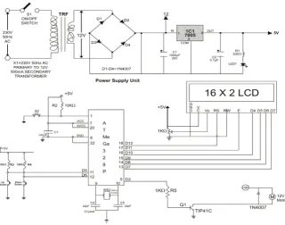
The circuit diagram shown in Figure 1 displays the DC motor speed controller circuit.
The whole assembly is composed of three main units namely; 1) the power source with its power-on reset switch sub-unit, 2) the main circuit (control unit) which obtains signals through the interrupt input switches, and 3) switching unit, incorporating the interrupt input switches and the switching power tran-sistor for the DC motor.
DOI: 10.4236/wjet.2019.74046 636 World Journal of Engineering and Technology
Figure 1. DC motor speed control circuit.
From this power supply unit, connection was made to the main circuit via switch S2. The oscillator circuit presented here to generate a pulse width mod-ulation signal uses an 8-bit microcontroller, ATmega 328P labelled IC2, pro-grammed by an ARDUINO C++ program. From the power supply pin, (1 of the microcontroller) connection is made to the power source using a 10 KΩ resistor, labelled R2, in series as a current limiter. Inputs to the appropriate pins of this microcontroller are made as shown in the circuit diagram. Output from the mi-crocontroller is connected to a 16 × 2 liquid crystal display, LCD which interfac-es this microcontroller, having a total of 32 characters (16 on each line). For each character there are 5 × 10 = 50 pixels, with all 50 pixels working together to dis-play each character. The pixels are controlled by another controller (HD44780) in the display unit. As the pin numbers are defined on the microcontroller, it displays data on the LCD. Up and Down push buttons, serve as the speed incre-ment and decrease switches. Two 10 KΩ resistors connected in series to these switches, labelled R3 and R4 regulates the current supplied to them. Two 22 pF non-electrolytic capacitors, labelled C4 and C5 are connected across the crystal oscillator, labelled XRO, and connected to pins 9 and 10 of the microcontroller.
Circuit Explanation
in-DOI: 10.4236/wjet.2019.74046 637 World Journal of Engineering and Technology terrupt is generated to change the duty cycle of the pulse train. The Up push button is interfaced to interrupt and increase the duty cycle of the pulse train while the Down push button is interfaced to interrupt and decrease the duty cycle of the pulse train. The duty cycle of the pulse waveform is displayed on the LCD. From Pin 5 of the microcontroller, connection is made to the base of an npn TIP41C transistor, (labelled Q1), via a 1 KΩ resistor labelled R5. This tran-sistor acts as a switch (in this case) for the 12 V D.C motor, labelled M, and from the transistor’s collector, connection is made to the motor M, and from the mo-tor to the Power source. Diode D5 is an IN4007 rectifier diode, connected in pa-rallel across the motor to prevent reverse current flow. A tachometer was con-nected to the D.C motor, M, which measures the speed of rotation of the motor. Outputs from the microcontroller (data pins 13 through 18 or data pins D7 through D12) are connected to the LCD. The LCD displays 10% of the value of the duty cycle, in other words, for a duty cycle of 10%, the LCD displays a value 1 and for a duty cycle 70%, the value displayed on the LCD is 7. The power for the LCD is sourced from the regulator of the power source. The wired compo-nents are shown in Figure 2.
[image:4.595.288.460.412.544.2]After wiring the components together, the assembly is encased with switch S1, labelled as power-on-off button, the Up and Down push buttons are labelled as speed increase and speed decrease as shown on the case, the LCD and a fan connected to the shaft of the motor are also displayed on the case as shown in
[image:4.595.287.461.576.706.2]Figure 3.
Figure 2. Wired components assembly.
DOI: 10.4236/wjet.2019.74046 638 World Journal of Engineering and Technology
3. Result
Pressing the speed decrease button, led to corresponding reduction in the speed of the DC motor and this is manifest in corresponding reduction of the speed of the fan. By pressing the speed increase button to increase the speed of the DC motor, corresponding increase of the speed of the fan was observed. The speed of rotation of the motor as measured by the tachometer is displayed in Table 1.
4. Discussion and Conclusion
[image:5.595.209.538.487.734.2]DC Motor speed controller devices find applications in many areas of life. It finds good use in industrial automation systems, robotic motion control and in a number of household appliances [7]. Its applications in small scale industrial settings will no doubt enhance the quest for development in a developing nation like ours. This developed microcontroller based control system to change the speed of a DC motor reported in this work will definitely improve the need for automation in small and medium scale industrial settings. The circuit compo-nents for this circuit have been identified, and the constructed circuit tested. This circuit was used to control the speed of an electric fan. It can also be used to control the dimness of a lamp, movement of small toys and a number of other applications. In this circuit, power loss is minimal consequent of using the PWM technique to control the motor’s speed. The power loss in the switching transis-tor is small because the transistransis-tor is either fully “on” or fully “off” giving it a li-near type of control which results in better speed stability. Also, the voltage am-plitude of the motor is constant, and hence the motor is at full strength always, which means that the motor can be rotated much more slowly without stalling.
Table 1. Speed of rotation of motor.
Motor Speed Setting Motor Speed (rpm)
Increase Decrease
0 0 0
1 682 682
2 1365 1365
3 2047 2047
4 2730 2730
5 3412 3412
6 4095 4095
7 4777 4777
8 5460 5460
DOI: 10.4236/wjet.2019.74046 639 World Journal of Engineering and Technology
Acknowledgements
This research did not receive any specific grant from funding agencies in the public, commercial or not-for-profit sectors.
Conflicts of Interest
The authors declare no conflicts of interest regarding the publication of this paper.
References
[1] Russel, Md.K. and Bhuyan, M.H. (2012) Microcontroller Based DC Motor Speed Control Using PWM Technique. Proceedings of the International Conference on
Electrical, Computer and Telecommunications Engineering RUET, Rajshahi,
Ban-gladesh, 1-2 December 2012, 519-522.
[2] Bhuyan, M.H. (2007) Wireless Control System for DC Motor to Position a Dish An-tenna Using Microcomputer. Daffodil International University Journal of Science and
Technology (DIUJST), 2, 44-49.
[3] Bhuyan, M.H., Rabby, M.A. and Tarik, M.M.G. (2010) Microcontroller Based Au-tomatic Traffic Light Control System Design. Proceedings of the National
Confe-rence on Electronics and Telecommunications for Digital Bangladesh, Dhaka, 2-3
June 2010, 139-142.
[4] Siskind, C.S. (1959) Electrical Machines Direct and Alternating Current. McGraw Hill Book Co., New York, USA.
[5] Shuler, C.A. and McNamee, W.L. (1986) Industrial Electronics and Robotics. McGraw Hill Book Co., New York, USA.
[6] Rashid, M.H. (2010) Power Electronics Circuits, Devices and Applications. Prentice Hall Inc., USA.
[7] Mathur, A. (2008) Microcontroller-Based DC Motor Speed Controller.