Appliance Getting Started
Guide
NetBackup 52xx Series
Release 2.5.2
The software described in this book is furnished under a license agreement and may be used only in accordance with the terms of the agreement.
Documentation version: 2.5.2 PN: 21283281
Legal Notice
Copyright © 2013 Symantec Corporation. All rights reserved.
Symantec, the Symantec Logo, the Checkmark Logo, NetBackup, and Veritas are trademarks or registered trademarks of Symantec Corporation or its affiliates in the U.S. and other countries. Other names may be trademarks of their respective owners.
This Symantec product may contain third party software for which Symantec is required to provide attribution to the third party (“Third Party Programs”). Some of the Third Party Programs are available under open source or free software licenses. The License Agreement accompanying the Software does not alter any rights or obligations you may have under those open source or free software licenses. Please see the Third Party Legal Notice Appendix to this Documentation or TPIP ReadMe File accompanying this Symantec product for more information on the Third Party Programs.
The product described in this document is distributed under licenses restricting its use, copying, distribution, and decompilation/reverse engineering. No part of this document may be reproduced in any form by any means without prior written authorization of Symantec Corporation and its licensors, if any.
THE DOCUMENTATION IS PROVIDED "AS IS" AND ALL EXPRESS OR IMPLIED CONDITIONS, REPRESENTATIONS AND WARRANTIES, INCLUDING ANY IMPLIED WARRANTY OF MERCHANTABILITY, FITNESS FOR A PARTICULAR PURPOSE OR NON-INFRINGEMENT, ARE DISCLAIMED, EXCEPT TO THE EXTENT THAT SUCH DISCLAIMERS ARE HELD TO BE LEGALLY INVALID. SYMANTEC CORPORATION SHALL NOT BE LIABLE FOR INCIDENTAL OR CONSEQUENTIAL DAMAGES IN CONNECTION WITH THE FURNISHING,
PERFORMANCE, OR USE OF THIS DOCUMENTATION. THE INFORMATION CONTAINED IN THIS DOCUMENTATION IS SUBJECT TO CHANGE WITHOUT NOTICE.
The Licensed Software and Documentation are deemed to be commercial computer software as defined in FAR 12.212 and subject to restricted rights as defined in FAR Section 52.227-19 "Commercial Computer Software - Restricted Rights" and DFARS 227.7202, "Rights in Commercial Computer Software or Commercial Computer Software Documentation", as applicable, and any successor regulations. Any use, modification, reproduction release, performance, display or disclosure of the Licensed Software and Documentation by the U.S. Government shall be solely in accordance with the terms of this Agreement.
http://www.symantec.com
Printed in the United States of America. 10 9 8 7 6 5 4 3 2 1
Symantec Technical Support maintains support centers globally. Technical Support’s primary role is to respond to specific queries about product features and functionality. The Technical Support group also creates content for our online Knowledge Base. The Technical Support group works collaboratively with the other functional areas within Symantec to answer your questions in a timely fashion. For example, the Technical Support group works with Product Engineering and Symantec Security Response to provide alerting services and virus definition updates.
Symantec’s support offerings include the following:
■ A range of support options that give you the flexibility to select the right amount of service for any size organization
■ Telephone and/or Web-based support that provides rapid response and up-to-the-minute information
■ Upgrade assurance that delivers software upgrades
■ Global support purchased on a regional business hours or 24 hours a day, 7 days a week basis
■ Premium service offerings that include Account Management Services For information about Symantec’s support offerings, you can visit our website at the following URL:
www.symantec.com/business/support/
All support services will be delivered in accordance with your support agreement and the then-current enterprise technical support policy.
Contacting Technical Support
Customers with a current support agreement may access Technical Support information at the following URL:
www.symantec.com/business/support/
Before contacting Technical Support, make sure you have satisfied the system requirements that are listed in your product documentation. Also, you should be at the computer on which the problem occurred, in case it is necessary to replicate the problem.
When you contact Technical Support, please have the following information available:
■ Operating system ■ Version and patch level ■ Network topology
■ Router, gateway, and IP address information ■ Problem description:
■ Error messages and log files
■ Troubleshooting that was performed before contacting Symantec ■ Recent software configuration changes and network changes
Licensing and registration
If your Symantec product requires registration or a license key, access our technical support Web page at the following URL:
www.symantec.com/business/support/
Customer service
Customer service information is available at the following URL: www.symantec.com/business/support/
Customer Service is available to assist with non-technical questions, such as the following types of issues:
■ Questions regarding product licensing or serialization
■ Product registration updates, such as address or name changes
■ General product information (features, language availability, local dealers) ■ Latest information about product updates and upgrades
■ Information about upgrade assurance and support contracts ■ Information about the Symantec Buying Programs
■ Advice about Symantec's technical support options ■ Nontechnical presales questions
contact the support agreement administration team for your region as follows: [email protected]
Asia-Pacific and Japan
[email protected] Europe, Middle-East, and Africa
[email protected] North America and Latin America
Technical Support
... 4Chapter 1
Introduction
... 9About NetBackup appliance deployment ... 9
About NetBackup appliance and Symantec Storage Shelf matched pairs ... 12
Chapter 2
Hardware installation
... 13About mounting NetBackup appliance components ... 13
Connecting network and configuration sources to a NetBackup appliance ... 14
Connecting the Symantec Storage Shelf to a NetBackup appliance ... 16
Applying power to a NetBackup appliance system ... 22
Chapter 3
Configuration
... 25About appliance configuration guidelines ... 25
About the appliance initial configuration ... 28
About NetBackup appliance roles and modes ... 32
About appliance system configuration sequence ... 33
About IPv4-IPv6-based network support ... 34
Adding an appliance media server name to a master server ... 36
Configuring a new appliance from the appliance interface ... 37
Configuring a new appliance from the appliance shell menu ... 49
About post appliance configuration tasks ... 57
Adding the disk space of a storage expansion unit to an appliance ... 58
Installing NetBackup client software on clients through CIFS and NFS shares ... 59
About configuring the maximum transmission unit size ... 60
About appliance and NetBackup documentation ... 61
Introduction
This chapter includes the following topics: ■ About NetBackup appliance deployment
■ About NetBackup appliance and Symantec Storage Shelf matched pairs
About NetBackup appliance deployment
NetBackup appliance deployment consists of the complete installation and configuration of all appliance components to create a backup environment that is ready to use.
The Symantec NetBackup Appliance Getting Started Guide provides you with the information to get your appliance environment operational. Updates to this document were expected at the time of release. For the latest version of this document with the most recent updates, click on the following link:
http://www.symantec.com/docs/DOC2792
Additonal language versions of the Symantec NetBackup Appliance Getting Started Guides are available on line at these locations:
■ NetBackup Deduplication 5000 Series Appliances
http://www.symantec.com/business/support/index?page=content&id=TECH145661&key=58991 ■ NetBackup Backup 5200 Series Appliances
http://www.symantec.com/business/support/index?page=content&id=DOC2792&key=58991 The following provides a brief description of the available appliance system components:
1
Chapter
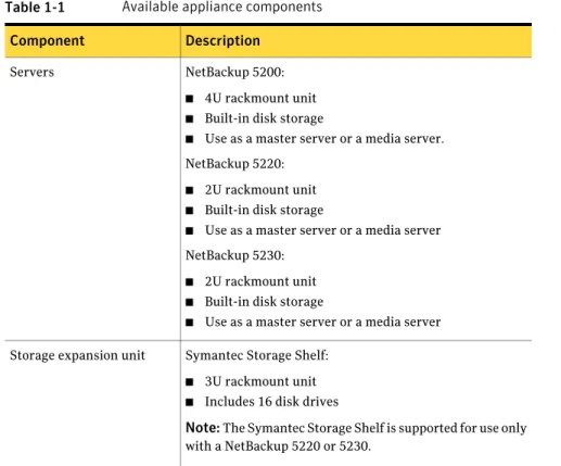
Table 1-1 Available appliance components
Description Component
NetBackup 5200:
■ 4U rackmount unit
■ Built-in disk storage
■ Use as a master server or a media server. NetBackup 5220:
■ 2U rackmount unit
■ Built-in disk storage
■ Use as a master server or a media server NetBackup 5230:
■ 2U rackmount unit
■ Built-in disk storage
■ Use as a master server or a media server Servers
Symantec Storage Shelf:
■ 3U rackmount unit
■ Includes 16 disk drives
Note:The Symantec Storage Shelf is supported for use only with a NetBackup 5220 or 5230.
Storage expansion unit
The following describes the supported NetBackup appliance configurations that you can deploy:
Table 1-2 Supported NetBackup appliance deployments
Deployment description System components
Single (standalone) NetBackup 5200, 5220, or 5230 appliance with combined master server and media server functionality. Master server
Single (standalone) NetBackup 5220 or 5230 appliance with combined master server and media server functionality and up to two Symantec Storage Shelf units.
Master server with storage expansion unit
A NetBackup 5200, 5220, 5230 master server, and a NetBackup 5200, 5220, or 5230 media server. Master server and media
servers
Same combinations as listed above, and up to two Symantec Storage Shelf units can be connected to each NetBackup 5220 or 5230.
Master server, media servers, storage expansion unit
The following describes the required tasks to deploy your NetBackup appliance environment:
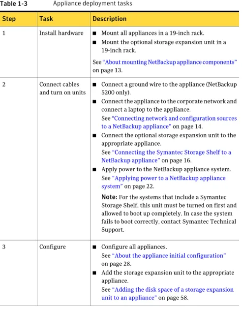
Table 1-3 Appliance deployment tasks
Description Task
Step
■ Mount all appliances in a 19-inch rack.
■ Mount the optional storage expansion unit in a 19-inch rack.
See“About mounting NetBackup appliance components” on page 13.
Install hardware 1
■ Connect a ground wire to the appliance (NetBackup 5200 only).
■ Connect the appliance to the corporate network and connect a laptop to the appliance.
See“Connecting network and configuration sources to a NetBackup appliance”on page 14.
■ Connect the optional storage expansion unit to the appropriate appliance.
See“Connecting the Symantec Storage Shelf to a NetBackup appliance”on page 16.
■ Apply power to the NetBackup appliance system. See“Applying power to a NetBackup appliance system”on page 22.
Note:For the systems that include a Symantec Storage Shelf, this unit must be turned on first and allowed to boot up completely. In case the system fails to boot correctly, contact Symantec Technical Support.
Connect cables and turn on units 2
■ Configure all appliances.
See“About the appliance initial configuration” on page 28.
■ Add the storage expansion unit to the appropriate appliance.
See“Adding the disk space of a storage expansion unit to an appliance”on page 58.
Configure 3
About NetBackup appliance and Symantec Storage
Shelf matched pairs
The NetBackup 52xx appliances ship with zero, one, or two storage shelves. When you order a NetBackup 52xx and a Symantec Storage Shelf together, these units are initialized together at the factory to create a matched pair. Matched pairs provide optimum performance and they should always be used together to help ensure successful installation and configuration.
Each storage shelf contains two numbers that show the matched set. The HOST number refers to the appliance to which a particular storage shelf is matched. The HOST and STORAGE numbers are located in either of the following locations: ■ On a white plastic panel that pulls out from the right, rear panel of the storage
shelf.
■ On a label that is located under the two SAS ports on the right, rear I/O module of the storage shelf.
If your system includes a second Symantec Storage Shelf, this secondary unit must be physically connected to the first Symantec Storage Shelf and not to the appliance.
Hardware installation
This chapter includes the following topics:■ About mounting NetBackup appliance components
■ Connecting network and configuration sources to a NetBackup appliance ■ Connecting the Symantec Storage Shelf to a NetBackup appliance ■ Applying power to a NetBackup appliance system
About mounting NetBackup appliance components
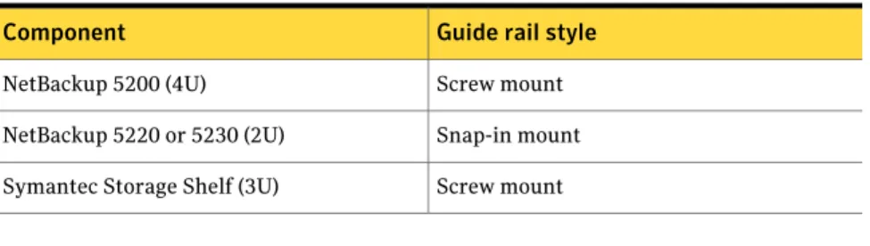
Each appliance system component includes guide rails and fasteners for installation in a 19-inch rack.The following describes the guide rail styles that are included with each system component:
Table 2-1 Guide rails styles for NetBackup appliance systems
Guide rail style Component
Screw mount NetBackup 5200 (4U)
Snap-in mount NetBackup 5220 or 5230 (2U)
Screw mount Symantec Storage Shelf (3U)
Note:Mounting methods vary by rack manufacturer. Racks may contain mounting rails with square holes, round holes, or round threaded holes. You may need to acquire other mounting hardware to install the guide rails in your rack. See“About NetBackup appliance deployment”on page 9.
2
Chapter
Connecting network and configuration sources to a
NetBackup appliance
After all appliance hardware installation is completed, you are ready to make all the necessary cable connections.
Use the following procedure to connect the network and the configuration sources to the appliance.
To connect the network and the configuration sources to the appliance
1
For 5200 appliances, connect your corporate network to the appliance ports as shown in the following diagram:Note:Make sure that you also connect a ground wire from the ground screw on the NetBackup 5200 appliance to a true earth ground.
Additional Ethernet ports (10GB) NIC3 (eth2) and higher
1GB Ethernet ports NIC2 (eth1)
Corporate network connection
NIC1 (eth0) Laptop connection NetBackup 5200
Ground connection (required)
Note:The number of expansion card ports (NIC3/eth2 and higher) varies depending on the hardware configuration that was ordered.
2
For 5220 appliances, connect your corporate network to the appliance ports as shown in the following diagram:F
1GB Ethernet ports NIC1 (eth0)
Laptop connection
NIC2 (eth1) Corporate network connection NetBackup 5220
RAID Controller and additional Ethernet ports (1GB or 10GB) NIC3 (eth2) and higher
Note:The number of expansion card ports (NIC3/eth2 and higher) varies depending on the hardware configuration that was ordered.
■ Connect a standard Ethernet cable from a laptop computer to appliance port NIC1.
The laptop is used to perform the initial configuration of the appliance. ■ For the systems that include a Symantec Storage Shelf, connect this device
to the appliance now by using the following procedure:
See“Connecting the Symantec Storage Shelf to a NetBackup appliance” on page 16.
3
For 5230 appliances, connect your corporate network to the appliance ports as shown in the following diagram:NetBackup 5230
NIC2 (eth1), NIC3 (eth2), NIC4 (eth3) Corporate network connections (1GB)
RAID Controller and additional Ethernet ports (10GB) NIC7 (eth6) and higher
NIC5 (eth4), NIC6 (eth5) Ethernet ports (10GB) NIC1 (eth0)
Laptop
connection (1GB)
Note:The number of expansion card ports (NIC7/eth6 and higher) varies depending on the hardware configuration that was ordered.
■ Connect a standard Ethernet cable from a laptop computer to appliance port NIC1.
The laptop is used to perform the initial configuration of the appliance. ■ For the systems that include a Symantec Storage Shelf, connect this device
to the appliance now by using the following procedure:
See“Connecting the Symantec Storage Shelf to a NetBackup appliance” on page 16.
Connecting the Symantec Storage Shelf to a
NetBackup appliance
The Symantec Storage Shelf (storage expansion unit) provides additional disk storage space. Starting with appliance version 2.5, you can add up to two of these units to one NetBackup 5220 or 5230.
Only one storage expansion unit can be physically connected to the appliance. For optimum performance, the storage expansion unit that is matched to work with your NetBackup 5220 or 5230 appliance must be physically connected to the appliance. If your system includes two storage expansion units, the secondary unit must be physically connected to the first unit (serial or daisy chain). The secondary unit cannot be connected directly to the appliance.
To help you identify matched pairs, a matched storage expansion unit has a label and a pull-out tab on the rear panel. For matched pairs, the label and the tab on the matching storage expansion unit identifies a HOST number. The host number is the serial number of the matching 5220 or 5230 appliance. The serial number of the appliance server is located on the left side of the front panel.
Note:The Symantec Storage Shelf that is matched to work with a 5220 or 5230 appliance must always be physically connected to the appliance.
Figure 2-1shows the label and the tab locations on the back of a storage expansion unit that is matched for use with a NetBackup 5220 or 5230 appliance.
Figure 2-1 Label and tab locations on a storage expansion unit
SAS In
SAS In SAS
Out
SAS Out
Tab location Label location
Note:The following procedures describe only how to connect communications cables. Do not apply power to any devices at this time. The power-up sequence is documented separately and is critical to help ensure correct communication between the appliance and any storage expansion units.
The following procedures describe how to connect the storage expansion unit to a NetBackup 5220 appliance.
To connect one storage expansion unit to a NetBackup 5220 appliance
◆ Connect two SAS cables to the SAS In ports on the storage expansion unit. Connect the other ends of the SAS cables to the available ports on the RAID card (slot 5) on the NetBackup 5220 appliance.
SAS In
SAS In SAS
Out
SAS Out
F
Slot 5—RAID controller NetBackup 5220
Symantec Storage Shelf (must be matched to your NetBackup 5220 appliance)
Warning:Once these connections are made, the storage expansion unit becomes an electrically integral part of the appliance. Any disconnection of these cables requires that you contact Symantec Technical Support.
To connect two storage expansion units to a NetBackup 5220 appliance
Note:This configuration is supported only in appliance software versions 2.5 and later.
1
Identify the storage expansion unit that is matched to your NetBackup 5220 appliance. This unit must be physically connected to the appliance.2
Connect two SAS cables to the SAS In ports on the storage expansion unit that is matched to your 5220 appliance. Connect the other ends of the SAS cables to the available ports on the RAID card (slot 5) on the NetBackup 5220 appliance.On the second storage expansion unit, connect two SAS cables to the SAS In ports. Connect the other ends of these SAS cables to the SAS Out ports on the first storage expansion unit.
Warning:Once these connections are made, the storage expansion unit becomes an electrically integral part of the appliance. Any disconnection of these cables requires that you contact Symantec Technical Support.
SAS In
SAS In SAS
Out
SAS Out
SAS In
SAS In SAS
Out
SAS Out
F
Slot 5—RAID controller NetBackup 5220
Symantec Storage Shelf-1 (must be matched to your NetBackup 5220 appliance)
The following procedures describe how to connect the storage expansion unit to a NetBackup 5230 appliance.
To connect one storage expansion unit to a NetBackup 5230 appliance
◆ Connect two SAS cables to the SAS In ports on the storage expansion unit. Connect the other ends of the SAS cables to the available ports on the RAID card (slot 1) on the NetBackup 5230 appliance.
SAS In
SAS In SAS
Out
SAS Out
Slot 1—RAID controller NetBackup 5230
Symantec Storage Shelf (must be matched to your NetBackup 5220 appliance)
Warning:Once these connections are made, the storage expansion unit becomes an electrically integral part of the appliance. Any disconnection of these cables requires that you contact Symantec Technical Support.
To connect two storage expansion units to a NetBackup 5230 appliance
Note:This configuration is supported only in appliance software versions 2.5 and later.
1
Identify the storage expansion unit that is matched to your NetBackup 5230 appliance. This unit must be physically connected to the appliance.2
Connect two SAS cables to the SAS In ports on the storage expansion unit that is matched to your 5230 appliance. Connect the other ends of the SAS cables to the available ports on the RAID card (slot 1) on the NetBackup 5230 appliance.On the second storage expansion unit, connect two SAS cables to the SAS In ports. Connect the other ends of these SAS cables to the SAS Out ports on the first storage expansion unit.
Warning:Once these connections are made, the storage expansion unit becomes an electrically integral part of the appliance. Any disconnection of these cables requires that you contact Symantec Technical Support.
SAS In
SAS In SAS
Out
SAS Out
SAS In
SAS In SAS
Out
SAS Out
Slot 1—RAID controller NetBackup 5230
Symantec Storage Shelf-1 (must be matched to your NetBackup 5220 appliance)
After you have made all of the necessary laptop, network, and Symantec Storage Shelf connections, proceed to the following topic to apply power to your appliance system:
See“Applying power to a NetBackup appliance system”on page 22.
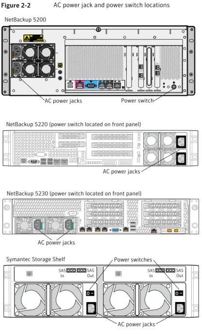
Applying power to a NetBackup appliance system
A NetBackup appliance system may consist of only appliance servers, or it may include Symantec Storage Shelf (storage expansion unit) units. For the systems that include storage expansion units, the power-up sequence is critical to help ensure correct communication with the appliance.Figure 2-2describes the AC power jack and the power switch locations on each unit.
Figure 2-2 AC power jack and power switch locations
F
NetBackup 5220 (power switch located on front panel)
Symantec Storage Shelf
AC power jacks Power switches
SAS In
SAS In SAS
Out
SAS Out
AC power jacks AC power jacks Power switch NetBackup 5200
NetBackup 5230 (power switch located on front panel)
AC power jacks
The following procedures describe the sequence in which units in the system should be turned on.
To apply power to units in the systems that consist only of appliance servers
1
Connect two power cables to each appliance, then plug in the other ends to the AC power source.2
Turn on each appliance server.The order in which the units are turned on is not critical.
3
Turn on the laptop computer.The appliance is now ready for configuration.
See“About appliance configuration guidelines”on page 25.
To apply power to units in the systems that consist of appliance servers and storage expansion units
1
Connect two power cables to each appliance, then plug in the other ends to the AC power source.Note:Do not turn on the appliance at this time.
2
Connect two power cables to each storage expansion unit, then plug in the other ends to the AC power source.3
Turn on all storage expansion units and wait for each unit to boot up completely.When all of the lights on the units stop blinking and are on steady, the boot up is complete.
4
Turn on all appliances.5
Turn on the laptop computer.The appliance is now ready for configuration.
Configuration
This chapter includes the following topics: ■ About appliance configuration guidelines ■ About the appliance initial configuration ■ About appliance system configuration sequence ■ About IPv4-IPv6-based network support
■ Adding an appliance media server name to a master server ■ Configuring a new appliance from the appliance interface ■ Configuring a new appliance from the appliance shell menu ■ About post appliance configuration tasks
■ About appliance and NetBackup documentation
About appliance configuration guidelines
Use the following configuration guidelines when you deploy new appliances:
3
Chapter
Table 3-1 Appliance configuration guidelines
Description Parameter
Before you start the configuration, make sure that you have the following information:
■ Network IP addresses, netmask, and gateway IP addresses for the appliance.
■ Network names for all appliances
■ DNS or host information
If DNS is used, make sure that the network names of all appliances and the master server are DNS resolvable (FQHN and short name).
Note:If DNS is not used, make sure that you enter the proper host entries for the appliance during the initial configuration. In the procedure "Configuring a new appliance from the appliance interface", you would not need to enter the DNS information in Step 7.
In the procedure "Configuring a new appliance from the appliance shell menu", you can skip Steps 4 - 6.
■ Password for appliance access
The default password for appliance access is P@ssw0rd.
■ Names for NetBackup storage units
The Storage Name fields appear only when you configure the appliance as a media server. You can change the default names or leave them.
Note:Only the storage unit name can be customized during the media appliance role configuration.
The default values that appear in the NetBackup Administration Console for the storage units and disk pools are as follows:
■ For the AdvancedDisk:
Default storage unit name: stu_adv_<hostname> Default disk pool name: dp_adv_<hostname>
■ For the NetBackup Deduplication:
Default storage unit name: stu_disk_<hostname> Default disk pool name: dp_disk_<hostname> Required names
Table 3-1 Appliance configuration guidelines (continued)
Description Parameter
Make sure that the following ports are open on any firewall that exists between a master server and a media server:
■ 13724 (vnetd)
■ 13720 (bprd)
■ 1556 (PBX)
■ 7578 (Specific for the 5220 when using TCP protocol)
■ 80 and 5900 (Specific for the 5200 when using TCP protocol) For more information about firewall ports for NetBackup and the NetBackup appliance, see the following Technote on the Symantec Support Web site.
http://www.symantec.com/docs/TECH178855 Firewall port
usage
Your appliance comes with an NFR license key that expires after a specific period of time. The appliance does not provide a warning message that this license key is about to expire. Thus, Symantec recommends that you change this key to a permanent key after you install and configure the appliance. See the Symantec NetBackup
Appliance Administrator's Guide for information and instructions on
how to view and change a license key.
Note:You must replace the keys with permanent keys before they expire.
Disk storage option licenses
NetBackup appliance Release 2.5.2 includes NetBackup version 7.5.0.5. To use an appliance media server with a traditional NetBackup master server, the master server must also use NetBackup version 7.5.0.5 or later. If the NetBackup master server currently uses NetBackup version 7.5.0.4 or earlier, it must first be upgraded to version 7.5.0.5 before you configure the appliance.
For all configurations, the master server must always use the same or a later version of NetBackup than the NetBackup version used on media servers. The only exception to this rule is if the media servers have a Maintenance Release installed. For example, a media server can have 7.5.0.x installed and be controlled by a 7.5 master server. NetBackup version
compatibility
See“About NetBackup appliance roles and modes”on page 32. See“About appliance system configuration sequence”on page 33.
About the appliance initial configuration
Figure 3-1shows an introductory page which provides an overview and a summary of the pages that follow.
Figure 3-1 Overview of appliance setup
Figure 3-2shows the Network Configuration page. The data entry fields are identified below the figure.
Figure 3-2 Network configuration page
■ Subnet Mask
■ NIC
■ Bond Mode
This field provides a drop-down list with the following options: ■ balance-rr
■ active-backup
■ balance-xor
■ broadcast
■ 802.3ad
■ balance-tlb
■ balance-alb (default)
For more information on bond modes, refer to the following:
See“Configuring a new appliance from the appliance interface”on page 37. http://www.kernel.org/doc/Documentation/networking/bonding.txt ■ Destination IP
■ Destination Subnet Mask
■ Default Gateway
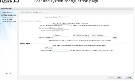
Figure 3-3shows the Host and System Configuration page. The data entry fields are identified below the figure.
Figure 3-3 Host and system configuration page
■ Host Name
■ DNS IP Address(es)
■ Domain Name Suffix
■ Search Domain(s)
■ Host Name Resolution
■ IP Address
■ Fully-Qualified-Hostname
■ Short-Hostname
For Failure Alerts: ■ SMTP Server
■ Email address(es)
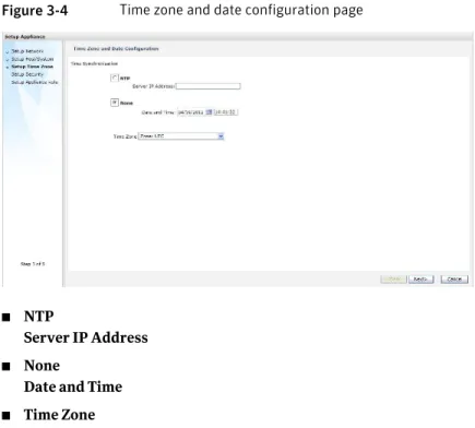
Figure 3-4shows the Time Zone and Date Configuration page. The data entry fields and options are identified below the figure.
Figure 3-4 Time zone and date configuration page
■ NTP
Server IP Address
■ None
Date and Time
■ Time Zone
Figure 3-5shows the Security Configuration page. The data entry fields are identified below the figure.
Figure 3-5 Security configuration
■ Old Admin Password
■ New Admin Password
■ Confirm New Admin Password
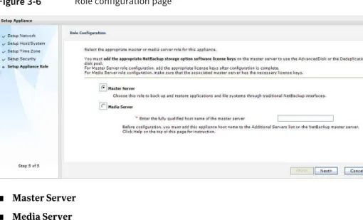
Figure 3-6shows the Role Configuration page. The data entry fields and options are identified below the figure.
Figure 3-6 Role configuration page
■ Master Server
■ Media Server
■ Enter the fully qualified host name of the master server (required only when Media Server is selected)
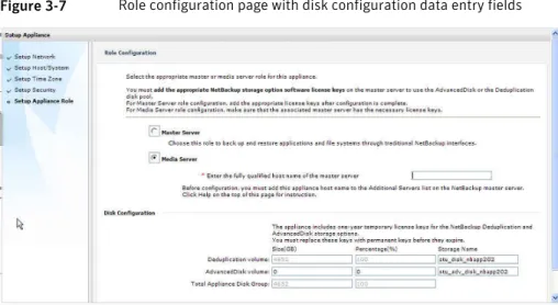
Figure 3-7shows the Role Configuration page with the disk configuration data entry fields. The data entry fields and options are identified below the figure.
Note:The Disk Configuration fields appear only when you select the media server role. When you perform the initial configuration for this role, only the Storage
Name for each volume can be changed. After you have completed the initial
configuration, you can change the size of each volume as needed by using one of the appliance interfaces.
Figure 3-7 Role configuration page with disk configuration data entry fields
The default values that appear for the storage unit and the disk volume names are as follows:
■ AdvancedDisk volume
Default storage unit name: stu_adv_<hostname> Default disk pool name: dp_adv_<hostname> ■ Deduplication volume
Default storage unit name: stu_disk_<hostname> Default disk pool name: dp_disk_<hostname>
About NetBackup appliance roles and modes
When you configure your appliance for the first time, you must select a role and a mode for the appliance. The role refers to the server type and the mode refers to the interface that is used for system administration.
Table 3-2 Appliance role and mode descriptions
Mode—user interface Role—server type
Select this role to configure the appliance as a master server. This role provides the traditional NetBackup interfaces to back up and restore applications and file systems.
Master Server
Select this role to configure the appliance as a media server. You must also identify the master server that you plan to use with this appliance. The master server can be either a traditional NetBackup master server or a NetBackup appliance master server.
A traditional NetBackup master server must have NetBackup version 7.5.0.5 or later installed. A NetBackup appliance master server must have appliance software version 2.5.2 or later installed.
When you select the media server role, you must also define the storage names for the following disk volumes:
■ Deduplication volume
■ AdvancedDisk volume Media Server
About appliance system configuration sequence
If your system includes more than one appliance or a storage expansion unit, configuration must be done in a specific order.The following describes the proper sequence for appliance configuration, based on the system components.
Table 3-3 Appliance configuration order
Configuration order System
Configure the appliance as a master server.
See“Configuring a new appliance from the appliance interface”on page 37.
See“Configuring a new appliance from the appliance shell menu”on page 49.
Single appliance system (standalone)
Table 3-3 Appliance configuration order (continued)
Configuration order System
■ Configure the first appliance as a master server.
■ Configure the remaining appliances as media servers for use with an appliance master server.
See“Configuring a new appliance from the appliance interface”on page 37.
See“Configuring a new appliance from the appliance shell menu”on page 49.
Multiple appliance system (master server and media servers)
Before you configure the appliance as a media server, you must first update the master server with the host name of this appliance.
Perform the following tasks in the order as shown:
■ Add the host name of this appliance to the master server. See“Adding an appliance media server name to a master server”on page 36.
■ Configure the appliance as a media server.
See“Configuring a new appliance from the appliance interface”on page 37.
See“Configuring a new appliance from the appliance shell menu”on page 49.
Appliance media server
After all appliances have been configured, add the storage expansion unit to the server on which it is physically connected.
See“Adding the disk space of a storage expansion unit to an appliance”on page 58.
Systems that include a storage expansion unit
About IPv4-IPv6-based network support
NetBackup appliances are supported on a dual stack IPv4-IPv6 network and can communicate with IPv6 clients for backups and restores. You can assign an IPv6 address to an appliance, configure DNS, and configure routing to include IPv6 based systems.
Either the Appliance Web Console or the appliance shell menu can be used to enter the IPv4 and IPv6 address information.
Review the following considerations for IPv6 addresses:
■ NetBackup appliances do not support a pure IPv6 network. An IPv4 address must be configured for the appliance, otherwise the initial configuration (which
requires the commandhostname set) is not successful. For this command to
work, at least one IPv4 address is required.
For example, suppose that you want to set thehostnameof a specific host to
v46. To do that, first make sure that the specific host has at least one IPv4 address and then run the following command:
Main_Menu > Network > Hostname set v46
■ Only global addresses can be used, not addresses with link-local or node-local scope. Global-scope and unique-local addresses are both treated as global addresses by SUSE.
Global-scope IP addresses refer to the addresses that are globally routable. Unique-local addresses are treated as global on SUSE.
■ You cannot use both an IPv4 and an IPv6 address in the same command. For example, you cannot useConfigure 9ffe::9 255.255.255.0 1.1.1.1. You
should useConfigure 9ffe::46 64 9ffe::49 eth1.
■ Embedding the IPv4 address within an IPv6 address is not supported. For example, you cannot use an address like 9ffe::10.23.1.5.
■ You can add an appliance media server to the master server if the IPv6 address and the host name of the appliance media server are available.
For example, to add an appliance media server to the master server, enter the IPv6 address of the appliance media server as follows:
Example:
Main > Network > Hosts add 9ffe::45 v45 v45 Main > Appliance > Add v45 <password>
You do not need to provide the IPv4 address of the appliance media server. ■ A pure IPv6 client is supported in the same way as in NetBackup.
■ You can enter only one IPv4 address for a network interface card (NIC) or bond. However, you can enter multiple IPv6 addresses for a NIC or bond.
■ Network File System (NFS) or Common Internet File System (CIFS) protocols are supported over an IPv4 network on appliance. NFS or CIFS are not supported on IPv6 networks.
■ The NetBackup client can now communicate with the media server appliance over IPv6.
■ TheMain_Menu > Network > Hostscommand supports multiple IPv6
addresses to be assigned to the same host name having one network interface card (NIC). However, only one IPv4 address can be assigned to a specific host name having one NIC using this command.
■ You can add an IPv6 address of a network interface without specifying a gateway address.
For more details, see the NetBackup Appliance Command Reference Guide.
Adding an appliance media server name to a master
server
Before you configure a NetBackup appliance as a media server, you must add its name to the master server that must work with this appliance.
Use the following procedure to add the network name of an appliance media server to a master server.
To add the network name of an appliance media server to a master server
1
Log in to the master server that must work with this appliance media server as follows:From the Appliance Web Console:
■ Click Manage > Additional Servers > Add.
■ In the Appliance Hostname field, enter the fully qualified host name (FQHN) of the appliance media server that you want to add.
■ Click Add.
If the appliance has more than one host name, you must add all of the names.
From the appliance shell menu:
■ From the Main_Menu > Appliance view, run the following command:
Settings > NetBackup AdditionalServers Add media-server
Where media-server is the fully qualified host name (FQHN) of the appliance media server that is not yet configured.
If the appliance has more than one host name, you must add all of the names.
For a configured and operational appliance master server:
■ Log on to the NetBackup Administration Console as the administrator.
■ On the main console window, in the left pane, click
NetBackup Management > Host Properties > Master Servers.
■ In the right pane, click on the master server host name.
■ On the Host Properties window, in the left pane, click Servers.
■ In the right pane, in the Additional Servers section, click Add and enter your appliance host name. The appliance host name should appear in the top
Additional Servers section.
If the appliance has more than one host name, you must add all of the names.
■ Click OK and close the Master Server Properties window.
For a traditional NetBackup master server:
2
Perform the initial configuration on the appliance media server as follows: ■ When the Role Configuration page appears, select Media Server. ■ Enter the name of the master server that you logged in to in step1Configuring a new appliance from the appliance
interface
The following procedure describes how to configure a new appliance by using the appliance user interface.
To configure a new appliance from the appliance user interface
1
On the laptop that is connected to the NIC1 appliance port, navigate to theLocal Area Connection Properties dialog box.
On the General tab, select Internet Protocol (TCP/IP) so that it is highlighted, then click Properties.
On the Alternate Configuration tab, perform the following tasks:
■
Note:For appliance versions 2.5.3 and later, the default IP address range has changed. You must use the following IP address range as described below.
For the IP address, enter192.168.229.nnn, wherennnis any number from 2 through 254 except for 233.
■ For the Subnet mask, enter 255.255.255.0. ■ Click OK.
2
On the laptop that is connected to the appliance, open a Web browser to the following URL:Note:For appliance versions 2.5.3 and later, the IP address assignment has changed. You must use the following IP address.
http://192.168.229.233
Make sure that you affirm the security exception to proceed.
3
Log on to the appliance as follows: ■ For User Name, enter admin. ■ For Password, enter P@ssw0rd.4
On the Overview of appliance setup page, review the summary of information that you need to perform the initial configuration. When you are ready to start the configuration, click Setup Appliance.5
On the Network Configuration page, you enter the IP addresses and other information that pertains to your network environment. This step describes the network information that you must provide.When you add entries to the Configure Network fields, those values are configured on the appliance after you click Add. The configuration entries then appear automatically in the read-only fields of the Applied Network Configuration table. The following describes the Configure Network fields.
■ IP Address
Enter an IPv4 or IPv6 address to be used for this appliance. Only global-scope and unique-local IPv6 addresses are allowed.
See“About IPv4-IPv6-based network support”on page 34.
■ Subnet Mask
Enter the subnet value that corresponds to the IP address.
■ NIC
This field displays the network device name that you can choose when you add a new network to the configuration. Use the following guidelines to bond NICs:
■ The NIC drop-down list shows the supported combination of appliance Ethernet ports that can be bonded. The list is compiled automatically and is based on the link types and the link speeds of the ports. Ports do not require connection to the network to appear in the list.
■ Select Auto to have the NICs selected automatically. This mode selects the best possible set of NICs to plumb the IP address on. The selection is based on the available NICs, the link type (copper or FC), and the link speed. If multiple NICs have the same properties, then a bond (link aggregation) is created and the IP address is plumbed on the bond.
■ Only NICs of the same type and speed can be bonded.
■ Once a NIC is bonded, it cannot be bonded to another NIC. To reassign a bond, you must first remove the NIC from its current bond.
Configure Network
■ Bond Mode
This field lets you combine (aggregate) multiple network interfaces into a single logical "bonded" interface. The behavior of the bonded interfaces depends upon the mode. The default bond mode is balance-alb.
The available bonding modes from the drop-down list are as follows:
■ balance-rr
■ active-backup
■ balance-xor
■ broadcast
■ 802.3ad
■ balance-tlb
■ balance-alb
Some bond modes require additional configuration on the switch or the router. You should take additional care when you select a bond mode.
For more information about bond modes, see the following documentation:
http://www.kernel.org/doc/Documentation/networking/bonding.txt After you enter all of the necessary information in the Configure
Network fields, you must click Add. The information that you
entered appears in the Applied Network Configuration table for confirmation.
Enter the kernel routing configuration of the appliance as follows:
■ Destination IP
Enter the network IP address of a destination network. The address can be either IPv4 or IPv6. Only global-scope and unique-local IPv6 addresses are allowed.
See“About IPv4-IPv6-based network support”on page 34. For the initial appliance configuration, this field contains a default value that cannot be changed. When you configure another destination IP, you must enter the appropriate address.
■ Destination Subnet Mask
Enter the subnet value that corresponds to the IP address. For the initial appliance configuration, this field contains a default value that cannot be changed. When you configure another route, you must enter the appropriate value.
■ Default Gateway
Enter the address of the network point that acts as an entrance to another network.
The address can be either IPv4 or IPv6. Only global-scope and unique-local IPv6 addresses are allowed.
See“About IPv4-IPv6-based network support”on page 34.
■ NIC
The appliance can use multiple network interface cards (NICs). This column displays the network device name.
Refer to the Linuxroutecommand for more information about how to add routing entries.
After you enter all of the necessary information in these fields, you must click Add. The information that you entered appears in the Applied Routing Configuration table for confirmation.
ConfigureRouting
6
Click Next.7
On the Host and System Configuration page, you enter the appliance host name information along with the SMTP server and email addresses for failure alerts. This step describes the host, the system, and the failure alert information that you must provide.Note:If DNS is not used, you do not have to enter DNS information in this step.
Host Name
Enter the fully qualified host name (FQHN) of the appliance name.
Note:For media servers to be used with a traditional NetBackup master server, make sure that you have already added the appliance name to the Additional Servers list on the NetBackup master server. That ensures that the appliance host name is resolvable from the master server.
■ DNS IP Address(es)
Enter the IP address of the DNS server.
The address can be either IPv4 or IPv6. Only global-scope and unique-local IPv6 addresses are allowed.
See“About IPv4-IPv6-based network support”on page 34. To enter multiple DNS IP addresses, use a comma character as the delimiter between each address and no spaces.
■ Domain Name Suffix
Enter the suffix name of the DNS server.
■ Search Domain(s)
You can enter one or more DNS search domain names to search when an unqualified host name is given. To enter multiple search domain names, use a comma character as the delimiter between each name and no spaces.
■ Host Name Resolution
■ IP Address
Enter the IP address of the appliance.
The address can be either IPv4 or IPv6. Only global-scope and unique-local IPv6 addresses are allowed.
See“About IPv4-IPv6-based network support”on page 34.
■ Fully-Qualified-Hostname
Enter the fully qualified domain name (FQHN) of the appliance.
■ Short-Hostname
Enter the short name of the appliance.
After you enter all of the necessary information in these fields, you must click Add. The Host Name Resolution information that you entered appears below these data entry fields for confirmation.
If DNS is not used, you should include host name entries for all of the following, as required.
■ All appliances including the one being configured
■ Master server
■ Non-appliance media servers
■ Clients
■ SNMP Server
■ SMTP Server
■ NTP Server
■ Call home server (www.symappmon.com)
DNS and Host Name Resolution
Enter the fully qualified host name (FQHN) of the SMTP (Simple Mail Transfer Protocol) server.
This server is used to send the notifications of alerts from the appliance to the email addresses that you enter in the following data entry field.
SMTP Server
Specify the Email IDs to receive any replies to the alerts or the reports from the appliance.
To enter multiple addresses, use a comma character as the delimiter between each address and no spaces.
Email address(es)
8
Click Next.The page clears and shows a status and a result for the host and the system configuration.
Click Next again.
9
On the Time Zone and Date Configuration page, you set the appropriate time and date for the appliance. You can select to use an NTP server or enter the information manually. This step describes the information that you must provide.Server IP Address
To use NTP (Network Time Protocol) to set the time and the date of the appliance, enter the IP address of the NTP server. The address can be either IPv4 or IPv6. Only global-scope and unique-local IPv6 addresses are allowed.
See“About IPv4-IPv6-based network support”on page 34.
NTP
Date and Time
To set the date and the time of the appliance without NTP, click
None and enter the appropriate date and time.
Enter the date manually by using the mm/dd/yyyy format, or click on the calendar icon and select the date.
Enter the time by using the hh:mm:ss format. Entries must be in the 24-hour format (00:00:00 - 23:59:59).
None
Whether you select to use NTP or None, you must set the time zone.
To set the time zone for the appliance, click on the Time Zone drop-down box and select the appropriate time zone.
10
Click Next.The page clears and shows the results of the time and date configuration. Click Next again.
11
On the Security Configuration page, you enter a new administrator's password for appliance access to replace the default password. This step describes the information that you must provide.Note:You are not required to change the default administrator's password. For increased security, Symantec recommends that you change the password periodically and keep a record of the current password in a secure location.
For the initial configuration, the default password isP@ssw0rd.
Old Admin Password
Enter the new password.
The password must be seven or more characters long. A seven character password must include all of the following requirements, while a longer password must include at least three of the following requirements:
■ One uppercase letter
■ One lowercase letter
■ One number (0-9)
■ One special character (for example, !, @, #, etc.) A password that begins with an uppercase letter and ends with a number is unacceptable, unless you include another uppercase letter and another number between them.
New Admin Password
Enter the new password again for confirmation.
Confirm New Admin Password
12
Click Next.The page clears and shows the results of the password configuration. Click Next again.
13
On the Role Configuration screen, you select either a master server role or a media server role for the appliance. If you select the media server role, you must also configure the built-in disk storage on the appliance. This step describes the information that you must provide.Choose the role for the appliance as follows:
■ Master Server
Select this role to configure the appliance as a master server.
■ Media Server
Select this role to configure the appliance as a media server. The associated master server can be a traditional NetBackup master server or an appliance master server. A traditional NetBackup master server must have NetBackup version 7.5.0.5 or later installed. An appliance master server must have appliance software version 2.5.2 or later installed. Before you continue with this selection, you must first add this appliance media server host name to the Additional
Servers list on the NetBackup master server.
To add this appliance media server host name to the
Additional Servers list on the NetBackup master server, do
the following:
■ On the master server, log on to the NetBackup Administration Console as the administrator.
■ On the main console window, in the left pane, click
NetBackup Management > Host Properties > Master Servers.
■ In the right pane, click on the master server host name.
■ On the Host Properties window, in the left pane, click
Servers.
■ In the right pane, in the Additional Servers section, click
Add and enter your appliance host name. The appliance
host name should appear in the top Additional Servers section.
If the appliance has more than one host name, you must add all of the names to the additional server sections on the master server.
■ Click OK and close the Master Server Properties window.
■ Continue here with the media server appliance role configuration by entering the fully qualified host name of the master server.
When you enter multiple names, the cluster name must be entered first. Then enter the remaining master server names and separate each name with a comma and no space.
Role
Note:The Storage Configuration fields appear only when you configure an appliance as a media server.
You can configure appliance disk unit storage as NetBackup Deduplication, AdvancedDisk, or a combination of both. By default, the entire disk is allocated for NetBackup Deduplication.
Note:Your appliance comes with an NFR license key that expires after a specific period of time. The appliance does not provide a warning message that this license key is about to expire. Thus, Symantec recommends that you change this key on the master server to a permanent key after you install and configure the appliance. See the Symantec NetBackup Appliance Administrator's
Guide for information and instructions on how to view and
change a license key.
To resize disk storage units, enter the size or the percentage of storage that you want to allocate for the AdvancedDisk disk partition. The remaining storage is calculated and assigned automatically to the NetBackup Deduplication partition. When both are added together, the new storage values for both disk volumes are displayed as the Total Appliance Disk Group. To create the storage partitions and the NetBackup storage units, do the following:
■ To configure the AdvancedDisk volume storage:
■ Enter the appropriate number in the Size (GB, TB, or PB) field or the Percentage (%) field.
■ The NetBackup disk pool is created automatically with the following name:dp_adv_<hostname>.
■ NetBackup Storage Unit Name
You can accept the default name or you can change it.
■ To configure the Deduplication volume storage:
■ Enter the appropriate number in the Size (GB, TB, or PB) field or the Percentage (%) field.
■ The NetBackup disk pool is created automatically with the following name:dp_disk_<hostname>.
■ NetBackup Storage Unit Name
You can accept the default name or you can change it.
Note:The disk pool names cannot be changed.
Note:If you have not allocated the entire storage space, the remaining storage appears as unallocated space that you may configure and use at any time.
Storage Configuration
14
To review your configuration selections, click Next. A pop-up window appears and asks you to verify that your appliance role configuration selection is correct. You can do one of the following:■ If you do not want to change any items, click OK. The summary page appears.
■ If you want to change any items, click Cancel. The Role Configuration page is still active and you can make changes to your configuration. Click
Next. The confirmation pop-up window appears for you to verify your
configuration selections. Click OK. The summary page appears.
15
After configuration has completed, wait about 10 minutes for the NetBackup services to start. You must then use the fully qualified host name to reconnect to the appliance.16
Repeat this procedure to configure all other new or unconfigured appliances.17
After all appliances have been configured, proceed to the following topic: See“About post appliance configuration tasks”on page 57.Configuring a new appliance from the appliance shell
menu
The following procedure describes how to configure a new appliance from the appliance shell menu.
To configure a new appliance from the appliance shell menu
1
On the laptop that is connected to the NIC1 appliance port, navigate to theLocal Area Connection Properties dialog box.
On the General tab, select Internet Protocol (TCP/IP) so that it is highlighted, then click Properties.
On the Alternate Configuration tab, perform the following tasks:
■
Note:For appliance versions 2.5.3 and later, the default IP address range has changed. You must use the following IP address range as described below.
For the IP address, enter192.168.229.nnn, wherennnis any number from 2 through 254 except for 233.
■ For the Subnet mask, enter 255.255.255.0. ■ Click OK.
2
Note:For appliance versions 2.5.3 and later, the IP address assignment haschanged. You must use the following IP address.
On the laptop that is connected to the appliance, open an SSH session to 192.168.229.233 and log on to your appliance.
The logon isadminand the default password isP@ssw0rd.
After you log on, the welcome message appears in the shell menu and the prompt is at the Main_Menu view.
3
From the Main_Menu > Network view, enter the following command to configure the IP address of a single network that you want your appliance to connect to.Configure IPAddress Netmask GatewayIPAddress [InterfaceNames]
Where IPAddress is the new IP address, Netmask is the netmask, and GatewayIPAddress is the default gateway for the interface. The
[InterfaceNames]option is optional.
The IP Address or the Gateway IP Address can be an IPv4 or IPv6 address. Only global-scope and unique-local IPv6 addresses are allowed.
Remember that you should not use both IPv4 and IPv6 address in the same command. For example, you cannot useConfigure 9ffe::9 255.255.255.0 1.1.1.1.. You should useConfigure 9ffe::46 64 9ffe::49 eth1
See“About IPv4-IPv6-based network support”on page 34.
If you want to configure multiple networks you must first configure the IP address of each network that you want to add. Then you configure the Gateway address for each network you added. You must make sure that you add the default Gateway address first. Use the following two commands:
Use either of the following commands depending on whether you want to configure an IPv4 or an IPv6 address for the network interface:
Configure the IP address of each network
To configure the IPv4 address of a network interface:
IPv4 IPAddress Netmask [InterfaceName]
Where IPAddress is the new IP address, Netmask is the netmask, and[InterfaceName]is optional. Repeat this command for each IP address that you want to add.
To configure the IPv6 address of a network interface: IPv6 <IP Address> <Prefix> [InterfaceNames] Where IPAddress is the IPv6 address, Prefix is the prefix length, and[InterfaceName]is optional.
Gateway Add GatewayIPAddress
[TargetNetworkIPAddress] [Netmask] [InterfaceName]
Where GatewayIPAddress is the gateway for the interface and TargetNetworkIPAddress, Netmask, and
InterfaceNameare optional. Repeat this command to add the gateway to all of the destination networks. The Gateway IP Address or the
TargetNetworkIPAddress can be an IPv4 or an IPv6
address.
Remember that you should not use both IPv4 and IPv6 address in the same command. For example, you cannot useGateway Add 9ffe::3 255.255.255.0 eth1. You should useGateway Add 9ffe::3 6ffe:: 64 eth1.
Configure the gateway address for each network that you added
4
From the Main_Menu > Network view, use the following command to set the appliance DNS domain name.Note:If you do not use DNS, then you can proceed to Step 7.
DNS Domain Name
Where Name is the new domain name for the appliance.
5
From the Main_Menu > Network view, use the following command to add the DNS name sever to your appliance configuration.DNS Add NameServer IPAddress
Where IPAddress is the IP address of the DNS server.
The address can be either IPv4 or IPv6. Only global-scope and unique-local IPv6 addresses are allowed.
See“About IPv4-IPv6-based network support”on page 34.
To add multiple IP addresses, use a comma to separate each address and no space.
6
From the Main_Menu > Network view, use the following command to add a DNS search domain to your appliance configuration so the appliance can resolve the host names that are in different domains:DNS Add SearchDomain SearchDomain
7
This step is optional. It lets you add the IP addresses of other hosts in the appliance hosts file.From the Main_Menu > Network view, use the following command to add host entries to the hosts file on your appliance.
Hosts Add IPAddress FQHN ShortName
Where IPAddress is the IPv4 or IPv6 address, FQHN is the fully qualified host name, and ShortName is the short host name.
See“About IPv4-IPv6-based network support”on page 34.
8
From the Main_Menu > Network view, use the following command to set the host name for your appliance.Hostname Set Name
Where Name is the fully qualified host name.
With this step, NetBackup is re-configured to operate with the new host name. This process may take a while to complete.
For the commandHostname setto work, at least one IPv4 address is required.
For example, you may want to set the host name of a specific host to v46. To do that, first ensure that the specific host has at least an IPv4 address and then run the following command.
Main_Menu > Network > Hostname set v46
9
From the Main_Menu > Settings view, use the following commands to enter the SMTP server name and the email addresses for appliance failure alerts.Email SMTP Add smtp [acct] [pass]
Where smtp is the host name of the target SMTP server,
acct is the account name for authentication to the
SMTP server, and pass is the password for authentication to the SMTP server. Enter the SMTP server name
Email Software Add eaddr
Where eaddr is the Email address where you want to receive failure alerts from the appliance.
To enter multiple addresses, separate each address with a semi-colon.
Enter email addresses
10
Select the role for the appliance and run the appropriate configuration commands as follows:From the Main_Menu > Appliance view, run the following command:
Master
■ Media Server
For use with an appliance master server
For this role, there is no command to enter. The initial configuration is complete.
The next task you must complete is to add the name of this media server to the configured appliance master server.
■ Media Server
Note:Before you configure this appliance as a media server, you must add the name of this appliance to the master server that must work with this appliance. See“Adding an appliance media server name to a master server” on page 36.
From the Main_Menu > Appliance view, run the following command:
Media MasterServer
Where MasterServer is either a stand-alone master server, a multihomed master server, or a clustered master server.
The following defines each of these scenarios: ■ Stand-alone master server
This scenario shows one master server host name. This name does not need to be a fully qualified name as long as your appliance recognizes the master server on your network. The following is an example of how the command would appear.
Media MasterServerName
■ Multihomed master server
In this scenario, the master server has more than one host name that is associated with it. You must use a comma as a delimiter between the host names. The following is an example of how the command would appear.
Media MasterNet1Name,MasterNet2Name
■ Clustered master server
In this scenario, the master server is in a cluster. Symantec
recommends that you list the cluster name first, followed by the active node, and then the passive nodes in the cluster. This list requires you to separate the node names with a comma. The following is an example of how the command would appear.
■ Multihomed clustered master server
In this scenario, the master server is in a cluster and has more than one host name that is associated with it. Symantec recommends that you list the cluster name first, followed by the active node, and then the passive nodes in the cluster. This list requires you to separate the node names with a comma. The following is an example of how the command would appear.
Media MasterClusterName,ActiveNodeName, PassiveNodeName,MasterNet1Name,MasterNet2Name
To prevent any future issues, when you perform the appliance role configuration, Symantec recommends that you provide all of the associated master server names.
Note:The remaining steps for disk configuration apply only for the appliances that are configured for the media server role.
11
If you selected the media server role, the default disk storage configuration for the appliance appears. The following example shows how the default information appears for the built-in disk storage on the appliance:Available Storage = xGB
Current Storage Pool Configuration:
Deduplication Storage = xGB (100%), AdvancedDisk = 0GB (0%)
12
The configuration process asks you if you want to configure your storage as AdvancedDisk.Do you want part of your storage configured as AdvancedDisk? (yes/no): y
Enter y to configure an AdvancedDisk volume.
13
You are then asked to enter the size of AdvancedDisk Volume.Enter Size of AdvancedDisk Volume (use a % sign if you want it as a percent of the total, or input size is GBs): 50%
Enter a percentage of the total storage, or enter a value that in Gigabytes (GB).