Flow Computer Division
Website: www.EmersonProcess.com/flow
Form A6091
Part Number D301138X012 May 2003
ROCLINK™ for Windows Configuration Software
User Manual
ii Rev 04/03
Revision Tracking Sheet
May 2003
This manual is periodically altered to incorporate new or updated information. The date revision level of each page is indicated at the bottom of the page opposite the page number. A major change in the content of the manual also changes the date of the manual, which appears on the front cover. Listed below is the date revision level of each page.
Page Revision
All Pages 05/03 (Software version 1.20) All Pages 09/02 (Software version 1.10) All Pages 03/01 (Software version 1.01)
ROCLINK is a mark of one of the Emerson Process Management companies. The Emerson logo is a trademark and service mark of Emerson Electric Co. All other marks are the property of their respective owners.
This product may be covered under pending patent applications. © Fisher Controls International, LLC. 2001-2003. All rights reserved. Printed in the U.S.A.
While this information is presented in good faith and believed to be accurate, Fisher Controls does not guarantee satisfactory results from reliance upon such information. Nothing contained herein is to be construed as a warranty or guarantee, express or implied, regarding the performance, merchantability, fitness or any other matter with respect to the products, nor as a recommendation to use any product or process in conflict with any patent. Fisher Controls reserves the right, without notice, to alter or improve the designs or specifications of the products described herein.
Rev 05/03 Table of Contents iii
TABLE OF CONTENTS
Section 1 – Getting Started... 1-1
1.1 USER MANUAL OVERVIEW... 1-1
1.2 COMPUTER REQUIREMENTS... 1-2
1.3 ROCLINK FOR WINDOWS CONFIGURATION SOFTWARE... 1-3 1.4 SOFTWARE INSTALLATION... 1-4 1.5 STARTING ROCLINK SOFTWARE... 1-7
1.6 CONNECTING THE COMPUTER TO THE ROC OR FLOBOSS... 1-8
1.7 USER INTERFACE... 1-9 1.8 CONFIGURATION OVERVIEW... 1-17
Section 2 – ROC Directory ... 2-1
2.1 ROC ROOT... 2-2
Section 3 – Configuring System Parameters ... 3-1
3.1 SETTING THE ROC CLOCK... 3-1
3.2 CONFIGURING ROC SYSTEM FLAGS... 3-2 3.3 CONFIGURING ROC INFORMATION... 3-8 3.4 SECURITY... 3-11
3.5 LCD USER LIST SETUP... 3-14 3.6 UPDATE FIRMWARE... 3-15 3.7 UPDATE HARDWARE... 3-17
3.8 UPGRADE TO FLASHPAC ... 3-18
Section 4 – Configuring Basic I/O ... 4-1
4.1 BASIC CONFIGURATION OVERVIEW... 4-1 4.2 AI – ANALOG INPUT CONFIGURATION... 4-5 4.3 AO – ANALOG OUTPUT CONFIGURATION... 4-7
4.4 DI – DISCRETE INPUT CONFIGURATION... 4-9
4.5 DO – DISCRETE OUTPUT CONFIGURATION... 4-12 4.6 PI – PULSE INPUT CONFIGURATION... 4-16
iv Table of Contents Rev 05/03
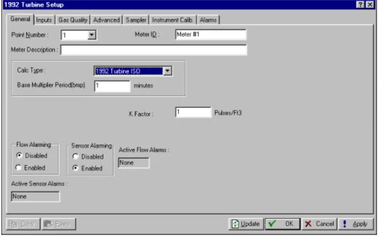
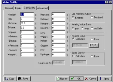
Section 5 – Configuring the Meter Setup... 5-1
5.1 METER SETUP...5-1
5.2 CONFIGURING AGA PARAMETERS...5-3
5.3 CALIBRATION AND AI CALIBRATION...5-22 5.4 PLATE CHANGE...5-29
Section 6 – Extended Functions ... 6-1
6.1 SOFT POINTS...6-1
6.2 TANK MEASUREMENTS...6-1
6.3 OPCODE TABLE...6-3 6.4 MVS SENSOR...6-4
6.5 TIMED DURATION OUTPUT (TDO) CONFIGURATION...6-7
PID 6-10
6.7 RADIO POWER CONTROL...6-17 6.8 MODBUS CONFIGURATION...6-21
6.9 MODBUS REGISTERS...6-30
6.10 DOWNLOAD USER PROGRAMS...6-37
Section 7 – Configuring and Viewing History ... 7-1
7.1 METER HISTORY...7-1 7.2 GENERAL HISTORY...7-5
7.3 HISTORY, ALARM, EVENT, AND AUDIT LOG REPORTS...7-10
Section 8 – Configuring Communications ... 8-1
8.1 COMMUNICATION PARAMETERS ON THE COMPUTER...8-1 8.2 COMMUNICATION PORTS ON THE ROC OR FLOBOSS...8-5
8.3 CONNECTING TO A ROC OR FLOBOSS...8-15
Section 9 – Saving / Retrieving Configurations... 9-1
9.1 SAVE TO EEPROM AND INTERNAL CONFIGURATION MEMORY...9-1
9.2 COLLECT DATA...9-2 9.3 VIEWING AND SAVING THE AUDIT LOG...9-3
9.4 SAVE...9-4
Rev 05/03 Table of Contents v
9.6 DOWNLOAD... 9-4
9.7 CONVERT FILES... 9-5
9.8 PRINT CONFIGURATION... 9-6
Appendix A – PID with TDO Control Example ... A-1
A.1 CONFIGURATION PROCEDURE... A-1 A.2 PROCESS VARIABLE CONFIGURATION... A-1
A.3 OPEN/FORWARD DISCRETE OUTPUT CONFIGURATION... A-2
A.4 CLOSE/REVERSE DISCRETE OUTPUT CONFIGURATION... A-4 A.5 PID PARAMETER CONFIGURATION... A-4
Appendix B – FST Editor...B-1
B.1 FUNCTION SEQUENCE TABLE INTRODUCTION...B-1
B.2 FST REGISTER PARAMETERS...B-2 B.3 FST EDITOR...B-4 B.4 FUNCTION STRUCTURE...B-6
B.5 BASIC RULES FOR CREATING FSTS...B-9
B.6 FSTS AND WRITING TO CONFIGURATION MEMORY...B-10 B.7 WORKING WITH FSTS...B-10 B.8 VIEW MENU – FST...B-13 B.9 MONITOR MENU – FST...B-16 B.10 MONITORING AN FST...B-17 B.11 COMMAND LIBRARY – FST...B-18 B.12 COMMAND EXAMPLES – FST...B-25 B.13 LOGICAL COMMANDS – FST...B-27 B.14 COMPARISON COMMANDS – FST ...B-29
B.15 TIME-RELATED COMMANDS – FST...B-30
B.16 CONTROL-RELATED COMMANDS – FST ...B-31 B.17 DATABASE COMMANDS – FST...B-33
B.18 MISCELLANEOUS COMMANDS – FST ...B-35
B.19 APPLICATION EXAMPLES – FST...B-36
vi Table of Contents Rev 05/03
Rev 05/03 Getting Started 1-1
SECTION 1 – GETTING STARTED
This section provides a summary of ROCLINK™ for Windows Configuration Software, installation,
hardware overview, basic software functions, user interface, and logging on to ROCLINK software.
1.1 User Manual Overview
This manual describes how to use ROCLINK software to configure and monitor FloBoss™ 103 Flow
Managers, FloBoss 500-Series Flow Managers, FloBoss 407 Flow Managers, ROC300-Series Remote Operations Controllers, and other devices. The software runs on a personal computer (such as a laptop or notebook style) that uses the Windows® operating system. This manual covers
configuration, calibration, monitoring, database archiving, custom displays, and embedded utilities.
NOTE: “ROC” is sometimes used in this manual and in ROCLINK for Windows software to stand for all ROC and FloBoss flow computer products.
1.1.1 Organization
This manual is organized based on how configuration occurs. Use this manual in conjunction with ROCLINK software on-line help system. Appendices in this manual supply examples and cover related topics. The manual includes major sections:
Section 2 – ROC Directory details the ROC Directory, which is the first screen that displays after logging on to ROCLINK for Windows software.
Section 3 – Configuring System Parameters describes how to set system preferences within the ROC or FloBoss, such as the Clock, Security, System Information, and Flags.
Section 4 – Configuring Basic I/O describes how to configure input and output options.
Section 5 – Configuring the Meter Setup describes how to configure a FloBoss or ROC to perform the basic functions used in a meter run.
Section 6 – Extended Functions describes how to configure a FloBoss or ROC to perform the extended functions used in a meter run.
Section 7 – Configuring and Viewing History describes how to configure a FloBoss or ROC for history archival. History can be archived for specific meter runs and for individual points and parameters within the ROC or FloBoss.
Section 8 – Configuring Communications describes how to Connect, Disconnect, and use Direct Connect to communicate to a ROC or FloBoss using ROCLINK for Windows software.
Section 9 – Saving / Retrieving Configurations describes how to save and retrieve configurations to and from a ROC or FloBoss.
1-2 Getting Started Rev 05/03
Appendix A – PID with TDO Control describes the Proportional, Integral, and Derivative (PID) control algorithm configurable as a Discrete Output control device for motorized applications.
Appendix B – FST Editor describes the Function Sequence Table (FST) capability provided by table-driven firmware that allows you to define actions to occur when a set of conditions exists.
Appendix C – Custom Displays describes the custom Display that allows you to create customized displays and load a display from a disk file to monitor flow and I/O points.
Index – alphabetically lists the items contained in this manual along with their page numbers.
NOTE: In most cases, the FloBoss units and ROC300-Series units are identical in operation. The descriptions and procedures in this manual apply to all FloBoss and ROC types unless otherwise noted.
NOTE: Refer to ROCLINK for Windows software on-line help for additional information.
1.2 Computer Requirements
ROCLINK software runs on most IBM-compatible personal computers (PCs). The PC can be a desktop or a portable computer. In any case, the PC should meet the following minimum requirements:
♦ CD-ROM drive.
♦ Windows 95 (Service Pack B), 98, ME, 2000, XP, or Windows NT 4.0 or higher.
♦ IBM-compatible PC with Pentium class processor (233 MHz recommended).
♦ 32 MB RAM.
♦ SVGA Color monitor with a minimum resolution of 800 x 600 pixels.
♦ Small system fonts (large fonts not supported).
♦ 10 MB of available hard disk space.
♦ EIA-232 (RS-232) serial connection (COM1 or COM2 on most computers), or a dial-up modem connection if the ROC or FloBoss has dial-up communications card installed.
Rev 05/03 Getting Started 1-3
1.3 ROCLINK for Windows Configuration Software
ROCLINK for Windows software provides the capability to monitor, configure, and calibrate the Remote Operations Controllers (ROC), and FloBoss Flow Managers Computers. The software and user documentation are supplied on a CD-ROM.
rlfunca.dsf
Sampler
ROCLINK for Windows Software Functions · Configure ROC/FloBoss operating parameters · Upload and download configurations
· Download historical data · Download alarm and event logs · Download EFM reports
· Examine configuration parameters · Monitor pressure, flow, and temperature
· Perform ROC/FloBoss maintenance and housekeeping ROCLINK
ROCLINK
Figure 1-1. Functions of ROCLINK for Windows Software
ROCLINK for Windows software has the capability to access Audit Logs in ROC and FloBoss units approved for Measurement (Industry) Canada custody transfer.
ROCLINK software is designed for ease of use. Drop-down menus simplify accessing the functions provided by the software. Dialog boxes and drop-down list boxes help to direct selections and data entry. You can perform actions with the keyboard or a pointing device, such as a mouse. Refer to Section 1.4 for a description of the user interface.
Help screens are accessed either from the Help menu or using the <F1> button. This feature makes it easy to access on-line information for any ROCLINK software topic.
You can build custom displays for the ROC or FloBoss that combine both graphic and dynamic data elements. The displays can monitor the operation of the ROC or FloBoss either locally or remotely. The software also provides multiple levels of security for controlling access to ROCLINK software functions, as well as the ROC or FloBoss database. Making changes to passwords or to the access level for personnel is accomplished through the ROC and Utilities menus, which are available only to an authorized person.
NOTE: If you are using a serial mouse (typically plugs into serial port COM1), be sure to set up communications to the ROC/FloBoss through a port that does not share interrupts (typically COM2) or a conflict could occur, locking up your PC.
1-4 Getting Started Rev 05/03
1.4 Software Installation
To use ROCLINK for Windows software to configure a hardware device, you must have the ROC or FloBoss wiring properly connected to power and I/O. Refer to the appropriate hardware instruction manual. Initially, the ROC or FloBoss should also be physically connected to a personal computer (PC) using the Local Operator Interface (LOI) port running ROCLINK software.
1.4.1 Installing ROCLINK for Windows Software using AutoRun
This sections details first time installation of ROCLINK software. If you already have a previous version of ROCLINK software installed, refer to Section 1.4.5, on page 1-6.
To install ROCLINK software on a PC with AutoRun, perform the following steps:
1. Place the ROCLINK Software Installation CD-ROM into your drive.
2. When the Main Menu screen appears, select the Install a ROCLINK Product button.
3. From the Installation Menu screen, select the Install ROCLINK for Windows button.
4. From the Setup Type screen, choose either Install a Newer Version or Update or Uninstall ROCLINK for Windows, and click Next.
5. Click Next in the ROCLINK for Windows Welcome screen.
6. A dialog box will appear asking if you would like to read the installation notes.
7. Read the License Agreement and click Confirm.
8. Enter your Name and Company name, and click Next.
9. Select the path if you want to install the software in a directory other than the default, C:\Program Files\ROCLINK for Windows. The ROCLINK for Windows default directory is recommended. Click Next.
10. Enter a name if you want the Start Menu program folder to be named other than the default, ROCLINK for Windows. The default is recommended. Click Next and click
Finish.
11. The Setup Complete screen will appear. If you have not yet read the readme file, leave it selected. Click the Finish button. Select View Manual or Exit on the Main Menu screen.
12. Once you have exited the Main Menu, remove the ROCLINK software installation CD-ROM.
1.4.2 Installing ROCLINK for Windows Software without AutoRun
This section details first time installation of ROCLINK software. If you already have a previous version of ROCLINK software installed, refer to Section 1.4.5, on page 1-6.
To install ROCLINK software on a personal computer, perform the following steps:
Rev 05/03 Getting Started 1-5 2. Click the Windows Start button.
3. Select Run.
4. Click the Browse button.
5. Navigate to and select the Setup.exe located on the ROCLINK for Windows CD-ROM.
6. Click OK in the Navigation window.
7. Click OK in the Run window.
8. Refer to the installation steps in Section 1.4.1, Installing ROCLINK for Windows Software using AutoRun.
1-6 Getting Started Rev 05/03
1.4.3 Manually Creating a Desktop Shortcut
ROCLINK for Windows software installation should automatically create a Desktop Shortcut on your computer. If for some reason you need to manually create the Desktop Shortcut:
1. Double-click the My Computer icon.
2. Navigate to the C:\Program Files\ROCLINK software For Windows\Bin
folder or the folder where you installed ROCLINK for Windows software.
3. Select the ROCLINK.exe file.
4. Select Create Shortcut from the File menu.
5. Click and drag the file Shortcut to ROCLINK.exe to your Desktop.
6. Double-click the Shortcut toROCLINK.exe icon on your desktop to launch ROCLINK software.
1.4.4 Launching ROCLINK for Windows Software during Startup
This procedure launches ROCLINK software each time you start this computer.
1. Double-click the My Computer icon.
2. Navigate to the C:\Program Files\ROCLINK For Windows\Bin folder or the Bin folder inside the folder where you installed ROCLINK software.
3. Select the ROCLINK.exe file.
4. Select Create Shortcut from the File menu.
5. Double-click the My Computer icon if the directory is not already displayed.
6. Navigate to the C:\Windows\Start Menu\Programs\Startup folder.
7. Click and drag the file Shortcut to ROCLINK.exe to the C:\Windows\Start Menu\Programs\Startup folder.
1.4.5 Upgrade
Procedure
This section details upgrading ROCLINK software from a previous version.
Insert the ROCLINK for Windows software upgrade CD. Install ROCLINK software using the procedure in Section 1.4.1, Installing ROCLINK for Windows Software using AutoRun, on Page 1-4. When the Setup Type screen appears, choose Install a Newer Version or Update, and click Next.
1.4.6 Un-Installing ROCLINK for Windows Software
To remove ROCLINK software from a personal computer, perform the following steps.
1. Click the Windows Start button.
2. Select Settings > Control Panel.
3. Double-click the Add/Remove Programs icon.
Rev 05/03 Getting Started 1-7 5. Click the Add/Remove button.
6. Click OK.
7. Click Finish.
1.5 Starting ROCLINK Software
This section details how to launch ROCLINK for Windows software.
NOTE: To use ROCLINK for Windows software to configure a hardware device, you must have the ROC or FloBoss wiring properly connected to power and I/O. Refer to the
appropriate hardware instruction manual. Initially, the ROC or FloBoss should also be physically connected to a personal computer (PC) using the Local Operator Interface (LOI) port running ROCLINK for Windows software.
To run ROCLINK software, perform one of the following:
♦ Double-click the Desktop shortcut created in Section 1.4.3 on page 1-6.
♦ Double-click ROCLINK.exe located in C:\Program Files\ROCLINK For Windows\Bin (the default directory) or wherever you installed ROCLINK software.
♦ Select Start > Programs > ROCLINK for Windows > ROCLINK For Windows.
The software loads and initializes. This may take a couple seconds or more, depending on the speed of your computer.
NOTE: You can only run one version of ROCLINK software at a time.
1.5.1 Logging
On
To log on to ROCLINK for Windows software:
1. Connect the ROC or FloBoss to the Local Operator Interface (LOI) port and launch ROCLINK for Windows software.
2. Type in your assigned 3-character identifier in the Login field and press <Enter> or <Tab>. Your initials are typically your identifier. If identifiers have not yet been assigned, try using the default Level 1 identifier of AAA or the default Level 6 identifier of LOI. Identifiers are assigned by using the security features of ROCLINK software.
3. Type in your assigned 4-digit Password and press <Enter> or click OK. For added security, the software displays an asterisk for each number that you type. If Passwords have not yet been assigned, try using the default password of 1000. ROCLINK software compares the entered identifier Login and Password to a list of valid ones. If the entries are valid, further access to the software is allowed.
1-8 Getting Started Rev 05/03
Press <Enter> and repeat steps 1 and 2. You can repeat the procedure as many times as needed until you successfully enter a valid Login and Password. If you want to exit from the log-on screen, press <Esc> or click Cancel. This aborts ROCLINK software and returns you to the point where you started ROCLINK software.
Security can be enabled by Identifier and Password or by Access level of the user. If Access Level security is enabled, then your Login and Password must also be valid for the unit. Refer to Section 3.4, ROC Security.
NOTE: You can only run one version of ROCLINK at a time. ROCLINK does not support multiple copies of ROCLINK running on the same computer at the same time.
1.6 Connecting the Computer to the ROC or FloBoss
This section details how to connect the computer to the ROC or FloBoss.
If the ports on both the computer and the ROC or FloBoss are configured properly, then a Connect
command causes the computer to begin communicating with the FloBoss or ROC through Comm 1 or Comm 2.
For connecting to a ROC or FloBoss locally using the Local Operator Interface (LOI) port, use the
Direct Connect to establish communications.
1.6.1 Local Hardware Connection – LOI
The PC running ROCLINK software physically connects to the ROC or FloBoss through a cable. For a local connection, this cable is typically a prefabricated operator interface (LOI) cable (available from the Flow Computer Division of Emerson Process Management). One end of the cable plugs into the ROC or FloBoss operator interface connector on the ROC or FloBoss enclosure. This connector is either a round, screw-cap-protected connector (Amphenol) for the FloBoss 407 or FloBoss 500-Series units or a 9-pin, D-shell, female connector for the ROC300-Series units. The other end of the cable plugs into a serial communications port on the PC running ROCLINK software. This connector is a 9-pin, D-shell, female connector.
By default, the LOI Port is Comm Tag Local Port in the ROC menu’s Comm Port Settings screen. Use the Direct Connect command to connect using the LOI. The Direct Connect option in
the ROC menu allows you to connect with the ROC or FloBoss quickly if the default
communication parameters apply. For the Direct Connect option to work, security conditions must be met, and the IBM-compatible personal computer (PC) must be connected to the Local Operator (LOI) port of the ROC or FloBoss with communication settings of:
♦ 8 Data Bits.
♦ 1 Stop Bit.
Rev 05/03 Getting Started 1-9
The Direct Connect command causes ROCLINK software to initiate communications with the ROC or FloBoss by performing a search of the PC communication ports at various baud rates. Direct Connect then “locks on” to the first Comm Port and Baud Rate that are successful in communicating with a FloBoss or ROC unit.
1.6.2 Remote Hardware Connection – Comm 1 and Comm 2
To connect the computer to a remotely located ROC or FloBoss, a serial or dial-up modem communications line must be installed. This connection is typically made through the host port (Comm 1 or Comm 2) on the ROC or FloBoss.
Use the Connect command to connect to a serial or dial-up modem.
1.6.3 Comm Port Configuration
Whether the PC running ROCLINK software is connected locally or remotely, the communication ports on the computer and the ROC or FloBoss must be configured similarly.
♦ The computer’s communications port is configured using the ROC Directory. Refer to Section 2, ROC Directory.
♦ The ROC or FloBoss communication port (LOI, Comm 1, or Comm 2) is configured using the ROC > Comm Ports window. Refer to Section 8, Configuring Communications.
1.7 User Interface
Users interact with ROCLINK software using various displays on the computer monitor and the computer keyboard and/or pointing device.
The major components of ROCLINK software user interface are:
♦ Menu bar and menus (affected by the security system).
♦ Function screens.
♦ Dialog boxes.
♦ Keyboard and pointing devices.
♦ Help system, including the Status Line and message boxes.
ROCLINK software employs a Graphical User Interface (GUI) with a standard Windows menu structure. After logging on to ROCLINK for Windows software, available functions display in a menu bar with drop-down menus. A Status Line at the bottom left of the display contains pertinent information about the highlighted item, such as a menu option or a parameter.
Buttons display dialog boxes for further configuration details or perform a desired action, such as the Update button. To activate the button:
♦ Click the button with a mouse.
1-10 Getting Started Rev 05/03
Dialog boxes are areas that “pop up” inside the current screen to allow further selections or values to be entered. They can also provide messages or information that is more detailed.
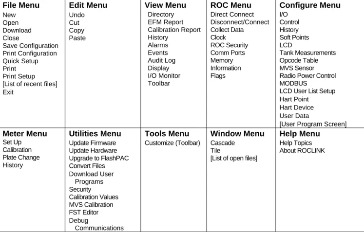
The menu structure displayed in Figure 1-2 lists choices from which you can select the desired function. Once a function is selected, the screen or dialog box for that function displays. This screen or dialog box provides the requested information and lets you enter the applicable configuration data. Refer to Figure 1-3. File Menu New Open Download Close Save Configuration Print Configuration Quick Setup Print Print Setup [List of recent files] Exit Edit Menu Undo Cut Copy Paste View Menu Directory EFM Report Calibration Report History Alarms Events Audit Log Display I/O Monitor Toolbar ROC Menu Direct Connect Disconnect/Connect Collect Data Clock ROC Security Comm Ports Memory Information Flags Configure Menu I/O Control History Soft Points LCD Tank Measurements Opcode Table MVS Sensor Radio Power Control MODBUS
LCD User List Setup Hart Point
Hart Device User Data
[User Program Screen]
Meter Menu Set Up Calibration Plate Change History Utilities Menu Update Firmware Update Hardware Upgrade to FlashPAC Convert Files Download User Programs Security Calibration Values MVS Calibration FST Editor Debug Communications Tools Menu Customize (Toolbar) Window Menu Cascade Tile
[List of open files]
Help Menu
Help Topics About ROCLINK
Rev 05/03 Getting Started 1-11
1.7.1 Menu Bar and Menus
The menu bar appears on the screen after successfully logging on. Your security level may limit the menus available from the menu bar.
Figure 1-3. Sample ROCLINK for Windows Software Display
From the menu bar, you can use either the keyboard or the mouse to activate a menu and then to select a function in that menu. You can also select functions using ToolBar Buttons or the Configuration Tree Menu. Status Line Menu Bar Configuration Tree Menu ToolBar Buttons Station Name
1-12 Getting Started Rev 05/03
1.7.2 Standard
Buttons
Several buttons appear on the majority of ROCLINK for Windows software screens.
Minimize and hide windows.
Maximize the size of the windows to fit in the screen area. Return to Original size of the window.
Close a window.
Expand options listed in the ROC Directory or Configuration Tree Menu.
Hide options listed in the ROC Directory or Configuration Tree Menu.
Copy contents of window to Clipboard.
Paste contents of the Clipboard to the active window.
Update contents of the active window.
Approve and close the active window. A Confirm Save dialog box appears if there are unsaved changes.
Cancel all changes and close the active window.
Apply changes to the active window. Create New parameter.
Save contents of the active window.
Close the active window. A Confirm Save dialog box appears if there are unsaved changes.
Rev 05/03 Getting Started 1-13
1.7.3 ToolBar
Select Customize from the Tools menu to add, delete, or rearrange the buttons that display on the ToolBar. Drag and drop the desired buttons from the Customize screen to ROCLINK software screen to add or remove buttons.
New file – Create a New Configuration File. Available configuration parameters can be
specified using menu selections. Configure the file as if you were connected to the device. The main difference is that functions requiring a live connection are unavailable in this mode.
Open a disk file – Open an existing configuration file. Configuration files are created using the New ROC and Save Configuration functions.
Save file – Saves the current configuration of the connected ROC or FloBoss to a disk file. Use this feature when multiple ROC or FloBoss units require similar configurations are being configured for the first time, or when configuration changes need to be made off-line. Once a backup configuration file is created, it can be loaded into a ROC or FloBoss with the Download function.
Cut – Delete currently selected text and place it in the Clipboard.
Copy – Duplicate currently selected text and place it in the Clipboard.
Paste – Place text currently in the Clipboard to location of the cursor.
AI Points – View the Analog Input window.
AO Points – View the Analog Output window.
DI Points – View the Discrete Input window.
DO Points – View the Discrete Output window.
PI Points – View the Pulse Input window.
Display1 – View Display1 stored in ROC memory. FloBoss 407 and ROC 300-Series only.
1-14 Getting Started Rev 05/03
Clock – View the ROC Clock window.
Comm Ports – View the Comm Ports Setting window.
Direct Connect – Connect to a ROC or FloBoss locally using the Local Operator Interface (LOI) port, with default settings.
Connect / Disconnect – Connect to or Disconnect from a ROC or FloBoss with a modem connection using Comm 1 or Comm 2.
Flags – View the ROC Flags window.
Meter Set up – View the Meter Set up window.
Configure PIDControl – View the PID Loop window.
Plate Change – View the Plate Change window.
Print – Print the configuration file.
Launch FST Editor – Launch the Function Sequence Table Editor.
Display Program Information – Display program information, version, creation date, and copyright of ROCLINK software.
Help – Display ROCLINK for Windows software on-line help system.
1.7.4 Keystrokes
If you are using the keyboard and the menu bar does not have one of its items (such as File) highlighted, use the Altkey plus the letter to activate the menu bar. For example: Press
<Alt + F> to activate the File menu. Use the <Left Arrow> and <Right Arrow> keys to highlight the menu bar item (the help Status Line at the bottom of the screen provides a description of the menu) and press the letter. For example: Press <Alt + F> and press <O> to select the Open file dialog.
With a menu displayed, you can highlight the desired item by using the <Down Arrow> and <Up Arrow> keys or the mouse. With the desired item highlighted, press the <Enter> key to activate the function.
Rev 05/03 Getting Started 1-15
To leave a menu or submenu, press the <Esc> key. You can then select another menu. You can also access another menu simply by using the <Left Arrow> and <Right Arrow> key.
The text scrolling keys are the <PageUp> and <Page Down> keys.
To use the keyboard in configuration screens and dialog boxes, press the <Tab> key to move in a predetermined sequence from one parameter field or button to the next. The selected field or button becomes highlighted. Fields unavailable for changes are automatically skipped.
When you <Tab> to the last field or button in the screen or dialog box, pressing the <Tab> key again jumps back to the first field or button. To go back to a previous field or button, press <Shift + Tab>. In an option field, the currently selected option is highlighted. To select one of the other options, use the <Up Arrow>and <Down Arrow> keys to highlight the desired option, and then press <Enter>. In a field that requires a text or numerical entry, type in the required characters or numbers from the keyboard. Use the <Backspace> or <Delete> keys to erase unwanted characters. Use the <Left Arrow> and <Right Arrow> to move the cursor one character at a time and the <Home> and <End> keys to place the cursor at the beginning and end of the field, respectively.
Other keys or key combinations include:
<F1> – Launches ROCLINK for Windows software on-line help.
<Esc>– Cancels the current activity, closes the screen, and returns you to the last-used place in the menu structure, screen, or other place from which the dialog box originated. If a menu is active, <Esc>closes the last-opened menu, taking you up one level in the menu structure. If the menu bar is active, <Esc>de-selects all menu options. Press the <Alt> key or click with the mouse to reactivate the menu bar.
<Ctrl + N> – Creates a new configuration file. <Ctrl + O> – Opens a configuration file.
<Ctrl + S> – Saves the current configuration file.
1.7.5 Help
System
The Help menu provides detailed on-screen information about getting started with ROCLINK software, performing keyboard operations. It lists the Help topics and provides ROCLINK software version.
The Status Line help serves two purposes: first, on the left side of the line, brief information about the currently highlighted menu item, configuration parameter, or button is provided; second, on the right side of the line, the communications port or file being used for configuration is indicated.
1-16 Getting Started Rev 05/03
1.7.6 Basic Navigation
When you initially connect to ROCLINK for Windows software, the ROC Root directory displays the Communication Directory Tree. Refer to Section 2, ROC Directory. After connecting to a ROC or FloBoss, the Configuration Tree Menu displays. Refer to Figure 1-4.
Figure 1-4. Typical Configuration Tree Menu
Use the + and – symbols to display or hide various options. Notice that valid points display. Double-click a point to display the associated parameter configuration screen. You can also use the menu options and buttons to display the associated parameter configuration screen.
1.7.7 Using Copy and Paste
Use Copy and Paste to copy data from one configuration screen to another of the same type.
1. Configure the meter run, point, screen, or other configuration you desire to duplicate.
2. Click Apply.
3. Click Copy.
4. Select the next Point Number or go to the appropriate screen.
5. Click Copy.
Rev 05/03 Getting Started 1-17
1.7.8 TLP Box Selections
Throughout ROCLINK software, the TLP Box is available for assigning specific inputs and outputs to parameters. ROCLINK software uses Point Type (T), Logical Number (L), and Parameter (P) to define point locations.
Figure 1-5. TLP Box – Point Type Definition
Interpret the information in the I/O Definition field (for example, AIN A 3, EU) in the following manner:
♦ The first part is a three-character mnemonic (in this example, “AIN” means Analog Input) that indicates the Point Type.
♦ The second part (such as “A 3”) indicates the Point Number.
♦ The third part is a mnemonic indicating the selected Parameter (such as EU for the Filtered Engineering Units Parameter).
To use the TLP Box:
1. Select the Point Type to use.
2. Select the exact Logical Number. For example: An Analog Input Point Type that you might select is AIN A 2.
3. Select the specific Parameter to use. For example: An Analog Input is typically Filtered EUs.
1.8 Configuration
Overview
If you are performing an on-line configuration for a ROC 300-Series or FloBoss 407, you must use the on-line Full Configuration procedure to set up your hardware as described in Section 1.8.1.
Configuration of a FloBoss 103 or FloBoss 500-Series unit can be performed off-line or on-line. Refer to Section 1.8.2. The advantage of off-line configuration is the ability to perform most of the configuration without connecting to the FloBoss. Off-line configuration is performed either by taking an existing configuration file, opening it, and making the desired changes (FloBoss 103 and 503/504) or by creating a new configuration file (FloBoss 503/504 only).
1-18 Getting Started Rev 05/03
1.8.1 Full Configuration
The full configuration procedure involves using the menu functions in roughly this order (some may not be required for your application or may not be available for your ROC/FloBoss):
♦ ROC menu > Security (logon)
♦ English or Metric Unit selection:
• ROC300-Series and FloBoss 407: Meter menu > Setup > Advanced tab
• FloBoss 103 and 500-Series: ROC menu > Information
♦ ROC menu > Clock
♦ ROC menu > Flags > Cold Start
♦ Meter menu > Set up
♦ Configure menu > I/O menu > AI, AO, DI, PI, and DO
♦ Configure menu > Control > PID
♦ Configure menu > History
♦ Configure menu > LCD User List Setup
♦ ROC Directory > Comm Ports – computer communication configurations
♦ ROC menu > Comm Ports – ROC and FloBoss communication configurations
♦ Configure menu > Radio Power Control
♦ Utilities menu > FST
♦ Utilities menu > Security (menu)
♦ ROC menu > Flags (for saving to internal configuration memory)
♦ View menu > Display > New or other
♦ Meter menu > Calibration
1.8.2 Quick Setup Configuration
Quick Setup is available when you connect to a FloBoss 103 or FloBoss 500-Series unit. Select File > Quick Setup. This method makes many assumptions about the configuration.
1.8.3 Duplicating a Configuration
Once you have completed the configuration and saved it to a disk file for one ROC or FloBoss, you can duplicate the configuration for a similar ROC or FloBoss by using these menu functions in the following order:
1. File > Save Configuration to save the configuration to a specified file.
2. File > Open is optionally used to modify configuration off-line.
3. ROC > Direct Connect (LOI) or Connect (modem) that physically connects the second unit, and then communicates using this function.
4. File > Download opens the configuration file and loads it to the unit.
After you have loaded configuration data into the second ROC or FloBoss (Step 4 above) and changed it as needed, you can save the configuration to its own disk file by using Step 1.
Rev 05/03 Getting Started 1-19
1.8.4 Creating a New Configuration
When connected (on-line) to a ROC 300-series or FloBoss 407 unit, new configurations are created by altering an existing configuration or the factory-set defaults.
To create a new configuration file for a FloBoss 500-Series:
4. Connect to a FloBoss, if working on-line.
5. Select New from the File menu or press <Ctrl + N>.
6. Select FB503 Configuration or FB504 Configuration.
7. Select Yes if you have an I/O Card installed and No if not.
8. Enter the total Number of PIDs you wish to configure.
9. Click OK.
10. Enter the name of the new configuration in the File Name field.
11. Click Save. The new configuration file is saved to the default directory C:\Program Files\ROCLINK for Windows\Data unless you specify otherwise. The file has the extension *.FCF (Flash).
Rev 05/03 ROC Directory 2-1
SECTION 2 – ROC DIRECTORY
This section details the ROC Directory, which is the first screen that displays after logging on to ROCLINK for Windows. The ROC Root directory provides a way to create and maintain
communications setup files for a PC running ROCLINK software to communicate to individual ROC and FloBoss units.
Figure 2-1. ROC Directory (Communications Directory Tree) Example
Use the + and – symbols to display or hide various options.
NOTE: Double-click the desired communications link (Station Name) to connect to that ROC or FloBoss. You may also select the menu bar or Toolbar button Direct Connect or Connect commands.
Refer to Section 8, Configuring Communications concerning how to configure communication ports on the ROC or FloBoss units.
LOI, Radio, or Serial TCP/IP Modem or Dial-up Group
2-2 ROC Directory Rev 05/03
2.1 ROC Root
The ROC Root directory is the top level of the organizational level in the Communications Directory Tree.
The ROC Root directory provides a way to create and maintain individual communications setup files for ROC and FloBoss units. When you install ROCLINK for Windows, ROC COMM1, ROC
COMM2, and Modem ROC display. You can use these communications setup files or you can create new files.
The communications setup files allow ROCLINK software to communicate to an individual ROC or FloBoss unit. You may add, delete, or modify these communications setups and establish Groups of ROC or FloBoss units.
The ROC Root directory files are used to set up personal computer (PC) communications ports (COM ports).
Each icon represents a different type of communications connection:
Local Communications Port, Serial Port, or Radio Connection.
Modem Port or Dial-up Connection.
TCP/IP Connection.
NOTE: If you are in a Configuration Tree menu, select Window > ROC Directory or View > ROC Directory to view the ROC Root directory.
Keep in mind that the ROC Root directory files are used to set up personal computer (PC) communications ports (COM ports). To set up communications for a specific ROC or FloBoss, use the Comm Ports and Information screens. Refer to Section 8, Configuring Communications
concerning how to configure communication ports on the ROC / FloBoss units.
For example: In Figure 2-2, if you select ROC COMM1 and Connect from the ROC menu,
communications with the ROC or FloBoss begins by using the communication parameters configured in ROC COMM1.
Rev 05/03 ROC Directory 2-3
The ROC and FloBoss units can be categorized to form Groups. A ROC/FloBoss Group is typically several units in the same geographical area or a number of units with something else in common. ROC and FloBoss units can be configured for on-line communications using either the Local Operator Interface (LOI) port or a communication port, such as when using a modem.
Each Group contains a list of all the ROC and FloBoss devices contained within that ROC Group. Each ROC or FloBoss has a Station Name (Tag) and unique ROCAddress with which to
differentiate each device. The physical ROC Station Name is setup in ROC Information. It is advised that you use the Station Name as the Tag. Each ROC and FloBoss is individually configured for communications.
The computers running ROCLINK software can also be categorized to form ROCLINKGroups. If more than one computer running ROCLINK software will be communicating with a group of ROC devices, either by radio or by other multi-drop communications, the ROCLINK Address of each ROC Directory setup must be unique to avoid multiple responses. The ROCLINK Address must also be different from any other host system that may access the network.
The ROC Group is the Group of similar ROC or FloBoss units and the ROC Address is the Address of the specific ROC or FloBoss with which you desire to communicate. If you are connected to a multi-drop series of ROC or FloBoss units, enter the exact and unique ROC Address and ROC Group of that specific ROC or FloBoss to talk to that device.
The Group and Address name are logged with the historical database for easy site identification.
NOTE: Once you are connected, the Configuration Tree menu becomes the active screen.
2.1.1 Adding a Group
To add a new Group under the ROC Root directory:
1. Select (highlight) the ROC Root directory icon.
2. Right mouse click.
3. Select Add a Group.
4. Type the name of the ROC or FloBoss Group in the New Groupxx field. Follow the instructions in Section 2.1.3 to add a ROC to this group.
2-4 ROC Directory Rev 05/03
Figure 2-3. New ROC in Group
Notice that a Group can have a Group under it. Refer to Figure 2-3. New Group2 has the sub-Group New sub-Group1.
NOTE: Once a ROC or FloBoss within the Group is configured, simply double-click the ROC or FloBoss icon under the Group to connect to that device. Once you are connected, the Configuration Tree menu becomes the active screen.
2.1.2 Deleting a Group
To delete a Group under the ROC Root directory:
1. Select a Group.
2. Right mouse click.
3. Select Delete Group.
4. Click Yes in the Confirm Delete Message dialog.
2.1.3 Adding a ROC Connection
To add a new ROC under the ROC Root directory:
1. Select (highlight) the ROC Root directory icon.
2. Right mouse click.
3. Select Add a ROC.
4. Type the Station Name of the ROC or FloBoss in the New ROCxx field.
5. Press <Enter>.
6. Configure the ROC or FloBoss communication parameters.
NOTE: You can nest a ROC connection under a Group by selecting the Group before adding the ROC Connection.
Rev 05/03 ROC Directory 2-5
2.1.4 Deleting a ROC Connection
To delete a ROC under the ROC Root directory:
1. Select a ROC by highlighting the Station Name next to its icon.
2. Right mouse click on the Station Name.
3. Select Delete ROC.
4. Click Yes in the Confirm Delete Message dialog.
2.1.5 Deleting All ROC Connections
To delete all ROC and FloBoss communication parameter configurations under the ROC Root directory:
NOTE: This deletes all ROC or FloBoss units that you currently have configured.
1. Select (highlight) the ROC Root directory icon.
2. Right mouse click.
3. Select Delete All ROCs.
4. Click Yes in the Confirm Delete Message dialog.
2.1.6 Renaming a Group or ROC Connection
To Rename a Group or ROC or FloBoss configuration parameter file:
1. Select (highlight) the ROC Station Name or Group label.
2. Right mouse click on the ROC Station Name or Group label.
3. Select Rename.
4. Type the new name of the Group label or ROC/FloBoss Station Name over the previous label or Station Name.
5. Press <Enter>.
NOTE: You can also rename a group or connection by highlighting the ROC or Group and clicking a second time to enable the field for editing.
Rev 05/03 Configuring System Parameters 3-1
SECTION 3 – CONFIGURING SYSTEM PARAMETERS
This section describes how to set system preferences within the ROC or FloBoss, such as the Clock, Security, System Information, and Flags.
3.1 Setting the ROC Clock
Immediately after connecting to a ROC or FloBoss for the first time, set the ROC Clock to ensure proper logging of history.
The internal real-time clock provides time-stamping and control of the historical databases, Event Log, Alarm Log, Audit Log, and Contract Hour.
NOTE: Make sure that the clock is correctly set before placing the ROC or FloBoss into service and beginning to log values, events, and alarms. The time stamp in the ROC reflects the time at the end of the period – not at the beginning. Data collected from 0800 to 0900 is thus time-stamped 0900.
2. Select ROC > Clock or click the Clock icon in the toolbar.
Figure 3-1. Clock
3. Use the arrow buttons to select the correct Month and Year. You can also click the Month to select the exact month or the Year and use the arrows to select the desired Year.
4. Click on the desired day of the month.
NOTE: The current date displays in the Today field. Click the Today field to synchronize the ROC or FloBoss with the same date and time as your computer.
5. Click on a time field and type in the desired value (type P or A for the AM/PM field) or use the arrows. You can also use the mouse to drag the hands on the clock to the desired position.
3-2 Configuring System Parameters Rev 05/03
For a FloBoss 103 or 500-Series unit, the clock can automatically compensate for daylight savings time by enabling this feature in the ROC Information screen. Refer to Section 3.3.1.
For a ROC300-Series or FloBoss 407 unit, the clock must be set manually or from a host computer to compensate. In the spring, the clock needs to be set ahead an hour to cause the historical log to skip an hourly log; in the fall, the clock needs to be set back one hour to cause a duplicate time-stamped hourly log to be entered.
3.2 Configuring ROC System Flags
This step helps to establish several parameters that affect the overall operation of the ROC. From this routine, a configuration can be saved to EEPROM or Internal Configuration Memory and the ROC can be reinitialized if necessary.
NOTE: Be very careful when using the ROC Flags. Certain Flags can cause data to be lost, parameter values to be changed, or configuration memory to be cleared. Be sure you
understand the function of the Flags before changing them.
3.2.1 Performing a Cold Start
It is advised that you perform a Cold Start directly after setting the ROC Clock and BEFORE setting any other parameters to ensure that the ROC or FloBoss unit’s memory is cleared before configuration begins.
In a Cold Start, the ROC or FloBoss is initialized from the restart configuration saved in
programmable ROM (internal configuration memory or Flash memory). If the configuration memory does not have a valid configuration written in it, the factory defaults in ROM are used.
Use the Cold Start when a ROC or FloBoss is performing erratically, the memory appears to be corrupted, or when you desire to reset the unit to the last saved configuration.
NOTE: Cold Start reloads all restart configuration data and may also clear logs, displays, and FSTs. In addition, it may cause output changes, load new accumulator values, and disable user program tasks and User Data Types. Generally, a Cold Start should not be used on a ROC or FloBoss that is actively gathering data and performing control. Save or document all required data and parameter values that could be affected before performing the Cold Start.
The following may occur when performing a Cold Start:
When using a ROC300-Series unit with a ROCPAC or a FloBoss 407,logs, ROC displays stored in ROC memory, and FSTs may be cleared. Any FSTs that exist must be manually started after the Cold Start by setting the FST Status parameter to “On” in the FST Parameters point. If FSTs were cleared, then they must be loaded from disk using the FST Editor utility. Clearing FSTs sets them to zero size, which can cause processor-loading problems if the FST is turned on.
Rev 05/03 Configuring System Parameters 3-3
When using a ROC300-Series unit with a FlashPAC, logs, ROC displays, and FSTs may be cleared. If a Write to EEPROM (which includes the FST run status) had been performed before the Cold Start, the FSTs will be in the same state after the Cold Start as when the Write to EEPROM was done (such as running if the FST was running). FST registers are always cleared upon restart;
therefore, use Softpoints to load initial values for the FST.
When using a FloBoss 500-Series unit, logs and FSTs may be cleared. If a Write to Internal Config Memory (which includes the FST and FST point) had been performed before the Cold Start, the saved FST reloads in place of the one that was cleared. If an FST was running when the FST was saved, the FST runs when the FST is reloaded by the Cold Start. FST registers are always cleared upon restart; therefore, use Softpoints to load initial values for the FST.
When using a FloBoss 103 unit, logs may be cleared. FSTs are not saved when a Write to Internal Config Memory is performed.
1. Select ROC > Flags.
2. Select the Cold Start checkbox in the Start Options field.
3. Click the Cold Start Options button.
Figure 3-2. Cold Start Options
2. Select Restore Config & Clear All of the above for a new installation and click OK.
3. Click Apply.
Other Cold Start options include:
None – Perform a Cold Start without restoring configurations.
Restore Config from Flash/defaults – Restore configuration from default values stored in Flash memory.
Restore Config & Clear Alarm/Log events – Restore configuration from default values stored in Flash memory and clear the Alarm Log and the Event Log.
Restore Config & Clear Roc Displays – Restore configuration from default values stored in Flash memory and clear the ROC Displays.
Restore Config & Clear FSTs – Restore configuration from default values stored in Flash memory and clear all FSTs.
Restore Config & Clear History – Restore configuration from default values stored in Flash memory and clear all History database files.
3-4 Configuring System Parameters Rev 05/03
Restore Config & Clear All of the above – Restore configuration from default values stored in Flash memory and clear all of the above.
3.2.2 Returning the ROC or FloBoss to the Factory Default Settings
Sometimes it is necessary to return the ROC or FloBoss to the original factory default settings. The following procedure clears all saved restart configuration data contained in programmableROM. Only factory defaults are retained.
To return the ROC or FloBoss to the original factory default settings:
1. Select ROC > Flags.
2. Select Clear Internal Config Memory or Clear EEPROM and click Apply.
3. Perform a Cold Start using the Restore Config & Clear All of the above option. Refer to Section 3.2.1, Performing a Cold Start, on page 3-2.
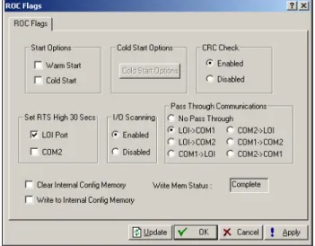
3.2.3 Setting ROC Flags
To set ROC Flags:
1. Select ROC > Flags. Refer to Figure 3-3 and Figure 3-4.
Figure 3-3. ROC Flags – FloBoss 500-Series Figure 3-4. ROC Flags – ROC300-Series with FlashPAC
Rev 05/03 Configuring System Parameters 3-5
Figure 3-5. ROC Flags – FloBoss 103
4. Select Cold Start or Warm Start to initialize the ROC / FloBoss from RAM if it is valid, which ensures databases and FSTs remain intact or if the RAM does not have a valid configuration, the configuration last saved to programmable ROM is used. This save is performed using Write to EEPROM or Write to Config Memory in the ROC Flags screen.
5. Select Enabled to perform a CRC Check (Cyclical Redundancy Check) on serial communications when using a FloBoss 500-Series.
6. Set RTS High for 30 secs for the operator interface port (LOI Port) or the COM port to activate the RTS (Request-to-Send) signal for that port when using a FloBoss 500-Series or FloBoss 103.
7. Select FST Display Clear to clear all FSTs and ROC Display 1 and 2 from RAM when using a ROC300-Series.
8. Select I/O ScanningEnabled to allow normal scanning mode when using a FloBoss 500-Series. When Disabled, all I/O scanning is stopped and the last values are used until the scanning is resumed.
9. Select a Pass Through Communications option to send Pass Through messages, when using a FloBoss 103. By using any of the FloBoss 103 communications ports, Pass Through allows data to be received by one unit and then passed through to other devices connected to any other communications port. For example, the host communicates via a radio on the LOI port. Other FloBoss 103 units can be connected to the EIA-485 (RS-485) port of the first unit, and all the FloBoss 103 units can use the same radio to communicate to the host.
NOTE: COM2 may only use a Dial-up modem if it is receiving Pass Through messages. COM2 cannot transmit to other field devices via Dial-up modem.
3-6 Configuring System Parameters Rev 05/03 10. Clear Internal Config Memory (FloBoss 103 and 500-series) – If selected and applied, all
saved restart configuration data contained in programmable ROM clears upon clicking Apply; only factory defaults are retained. When the memory is cleared, the checkbox is automatically deselected.
11. Clear EEPROM (FloBoss 407 and ROC300-series) – If selected and applied, all saved restart configuration data contained in programmable ROM clears upon clicking Apply; only factory defaults are retained. When the memory is cleared, the checkbox is automatically deselected.
12. Write to Internal Config Memory (FloBoss 103 and 500-series) – If selected and applied, most configuration settings, including the current states of the ROC Flags and calibration values (for a FloBoss 500 only, the FST is also saved), load into programmable ROM as the new restart configuration. When the loading is complete, the Write Status indicator shows “Complete” and the checkbox is automatically deselected.
All user Flags are maintained at their current status during this process. Writing to Configuration Memory causes all incoming communications to be temporarily suspended. If an FST is running, the FST is temporarily suspended, but restarts where it was suspended.
13. Write to EEPROM or Write to Config Memory (FloBoss 407 and ROC300-series) – If selected and applied, most configuration settings, including the current states of the ROC Flags and calibration values, loads into programmable ROM as the new restart configuration. Refer to the Cold Start parameter for more information. When the loading is complete, the Write Status indicator shows “Complete” and the checkbox parameter is automatically grayed out. The write process can take from a second to a minute or more for a large configuration.
When a Write to EEPROM is performed, all user Flags are maintained at their current status during this process and all incoming communications are temporarily suspended. In addition, all FSTs in the FloBoss 407 or ROC300-series unit restart.
14. Select the User Program options to enable or disable different user programs: Op Port,
COM1, COM2, Calc, and LCD User Program.
15. Perform a Warm Start or cycle power off/on to complete the activation
3.2.4 Advanced
Features
–
ROC Flags
When using a ROC300-Series or FloBoss 407, the Advanced Features tab is available in the ROC Flags screen.
Rev 05/03 Configuring System Parameters 3-7
Figure 3-6. ROC Flags – Advanced Features ROC300-Series (ROCPAC)
Figure 3-7. ROC Flags – Advanced Features FloBoss 407
2. Select CRC CheckEnabled to perform CRC (Cyclical Redundancy Check) checking on serial communications.
3. Select I/O ScanningEnabled so I/O is in normal scan mode. When Disabled, all I/O scanning is stopped and the last values are used until scanning is resumed.
4. Specify the RTSSettings as the number of seconds (0-255) for the respective port (Op Port, COM 1, or COM 2) and then click Apply to activate the RTS (Request-to-Send) signal. The RTS signal turns on for the specified amount of time. ROC300-Series with FlashPAC or FloBoss 407 only.
When using a ROC300-Series with ROCPAC or a FloBoss 500-Series select the respective port (Op Port, COM 1, or COM 2), click Apply to activate the RTS (Request-to-Send) signal. The RTS signal turns on for 30 seconds.
5. Select Read I/O to force the processor to read all the I/O types installed and compare them to the last saved configuration. If the I/O types are not the same, which could be caused by the installation of an additional I/O module, the database points found different are read. A new I/O module receives a default configuration. This Flag is normally used only by other ROC Flags.
16. Selectthe A4/A5 Function to determine whether the two built-in DI/PI channels in the ROC306 or ROC312 are configured.
17. Selectthe Auxiliary Outputs to turn Auxiliary Output #1 or Auxiliary Output #2 On or Off. On a ROC306 or ROC312 with a ROCPAC, these Flags need to be deselected to allow the auxiliary output to be used as a control output.
3-8 Configuring System Parameters Rev 05/03 18. Select the Transmitter Power flag to turn the “+T” transmitter power on (selected) or off
(deselected). For a FloBoss 407 that has a Rev C or D Termination Board, this Flag should not be selected.
3.3 Configuring ROC Information
This step establishes the Station Name, Address, Group, and other global variables that differentiate each individual ROC or FloBoss. Other system variables set in the ROC Information screen must be established for a particular application. Refer to Figure 3-8.
1. Select ROC > Information.
2. Enter the Station Name to be logged with the historical database for easy site identification.
Figure 3-8. ROC Information – FloBoss 500-Series
3. Enter a unique Address with which to differentiate each individual device among all units in a communications group. The Address can be assigned a value from 1 to 255. 240 is the System Default Address and should not be used. The host performs a search by looking at the Group and Address fields of every ROC or FloBoss on the network until it finds a match.
4. Enter a Group to identify a set of ROC or FloBoss units for communication purposes, typically to a host that polls the ROC. The station Group can be assigned a value from 1 to 255. All of the ROCs addressed as an area in the host have the same station Group. 240 is the system default Group and should not be used.
5. Set the Contract Hour time when values are totaled for a single day of production,
accumulators are cleared, and data is logged to the Daily History database. The Contract Hour is based on a 24-hour clock with midnight as the “0” hour.
6. When using a FloBoss 500-Series or FloBoss 103, select either US (English/Imperial) or Metric Units for calculations.
Rev 05/03 Configuring System Parameters 3-9 7. Select Force End of Day and click Apply to cause the current day and its hourly values to be
logged into memory for all historical data except station totals. Force End of Day resets the daily and hourly accumulators.
8. Select ROC Flags > Write to Internal Config Memory or Write to EEPROM.
3.3.1 Points
–
ROC Information
The Points screen allows you to set other parameter options, such as the number of available PID, AGA, Tank (ROC300-Series with a ROCPAC), and History Points. You may change the number of certain points that you want to be active.
1. Select ROC > Information and click the Points tab.
Figure 3-9. Points – FloBoss 500-Series Figure 3-10. Points – ROC300-Series
2. Enter the number of Active points, which must not exceed the amount available. To conserve resources, activate only the number of points you actually need. Refer to Table 3-1.
Table 3-1. Maximum Number of Applications
ROC306/ROC312 ROC364 FloBoss 103 FloBoss 407 FloBoss 500s
Maximum PIDs 6* 16 1 4 3
Maximum AGAs 3 5 1 4 1
Maximum Tanks
(ROCPAC only) 3 8 – – –
Maximum FSTs 4 4 1 4 2
*Older versions of ROCPACs support four PID points.
3. Enter the number of History Points. The amount available displays for each of the three RAM areas. To reduce processor loading, the number of database points configured should be set to the number of points actually needed.
3-10 Configuring System Parameters Rev 05/03 4. Enter the number of Base RAM database points contained in the Base RAM area. This field
accepts a value from 0 to 30; however, only 15 points are available for FloBoss 500-Series units. In ROC300-Series units with ROCPACs, due to the amount of RAM available in the Base RAM, the number of days of hourly data that can be archived is dependent upon the number of database points configured.
NOTE: Once the number of database points is defined and the ROC or FloBoss has been running, values are archived in the ROC database. Changing the number of database points in any RAM location re-initializes the history database, causing all previously archived values to be lost.
5. Enter the number of RAM1 database points contained in the first additional RAM area (in a ROC300-Series unit with a ROCPAC, 128K of an optional RAM module). This field accepts a value from 0 to 30; however, a maximum of 20 is actually available for a FloBoss 407, and none are available for a FloBoss 500-Series. Each database point contains 35 days of hourly data or 840 entries.
NOTE:Although only 20 points are possible for a FloBoss 407, ROCLINK software may take values greater than 20, and the corresponding history points show up in database configuration. However, you cannot actually configure them.
6. Enter the number of RAM2 database points contained in the second additional RAM area in a ROC300-Series unit (for ROCs with ROCPACs, 128K of an optional RAM module). This field accepts a value from 0 to 30 when used with a ROCPAC and from 0 to 27 when used with a FlashPAC. Each database point contains 35 days of hourly data or 840 entries. Unavailable for a FloBoss 407 or FloBoss 500-Series units.
7. Enable Automatic Daylight Savings Time Set for a FloBoss 103 or 500-Series device to set the Clock and the associated time stamping of logs automatically to daylight savings time in the spring and back to standard time in the fall. This takes place on the first Sunday in April where the time increments from 1:59:59 am to 3:00:00 am and on the last Sunday in October when the time reverts from 1:59:59 am to 1:00:00 am. In the spring, the historical log skips an hour and in the fall, a duplicate time value is entered.
3.3.2 Other Information
–
ROC Information
Select ROC > Information and click Other Information tab. This information is read-only.
Customer Name – The name of the customer for which the ROM version was created. The customer name can be set at the factory at the time of ordering or in the field by a sales representative.
Version Name – Displays the part number and version of the installed firmware.
ID# – Identifies the creator of the firmware.