Dell Hyper-V Cloud Fast Track Reference
Architecture for vStart200
Reference Architecture and Validation Guide
Release 1.3 for Dell 12
thgeneration servers
Dell Virtualization Solutions Engineering
Revision: A00
This document is for informational purposes only and may contain typographical errors and
technical inaccuracies. The content is provided as is, without express or implied warranties of
any kind.
© 2012 Dell Inc. All rights reserved. Dell and its affiliates cannot be responsible for errors or
omissions in typography or photography. Dell, the Dell logo, and PowerEdge are trademarks of
Dell Inc. Intel and Xeon are registered trademarks of Intel Corporation in the U.S. and other
countries. Microsoft, Active Directory, Hyper-V, SQL Server, Windows, Windows PowerShell, and
Windows Server are either trademarks or registered trademarks of Microsoft Corporation in the
United States and/or other countries. Other trademarks and trade names may be used in this
document to refer to either the entities claiming the marks and names or their products. Dell
disclaims proprietary interest in the marks and names of others.
Table of Contents
1
Introduction
... 1
1.1
Validation Criteria
... 1
2
Technical Overview
... 1
2.1
Cloud Attributes
... 1
2.2
Hyper-V Cloud Architecture Principles
... 2
2.2.1 Resource Pooling ... 2
2.2.2 Elasticity and Perception of Infinite Capacity ... 2
2.2.3 Perception of Continuous Availability ... 2
2.2.4 Drive Predictability ... 2
2.2.5 Metering/Chargeback (Service Provider’s Approach to Delivering IT) ... 3
2.2.6 Multi-Tenancy ... 3
2.2.7 Security and Identity ... 3
2.3
Conceptual Architecture
... 3
2.3.1 Scale Units... 42.4
Servers
... 4
2.5
Storage
... 4
2.6
Networking
... 4
2.7
Virtualization
... 5
2.8
Automation
... 5
2.9
Management
... 6
2.10
Orchestration
... 6
2.11
Service Management
... 6
2.12
Tenant / User Self-Service
... 7
3
Reference Architecture
... 8
3.1
Workload Categories
... 8
3.1.1 Server Virtualization and Consolidation ... 8
3.1.2 Virtual Desktop Infrastructure ... 9
3.2
Logical Architecture
... 11
3.3
Server Architecture
... 12
3.3.1 Rack Design ... 13
3.3.2 Server Design ... 14
3.3.3 Server Storage Connectivity ... 15
3.4
Storage Architecture
... 18
3.4.1 Storage Options ... 19
3.4.2 SAN Storage Protocols ... 19
(1) iSCSI vs. FC vs. FCoE ... 19
(2) Storage Network ... 20
3.4.3 Clustered File Systems (3rd Party) ... 21
3.4.4 Cluster Shared Volumes ... 22
(1) CSV Limits ... 22 (2) CSV Requirements ... 22 (3) CSV Volume Sizing ... 23 3.4.5 SAN Design ... 24 (1) High Availability ... 25 (2) Performance ... 26 (3) Drive Types ... 26
(4) RAID Array Design ... 27
(5) Multi-Pathing ... 27
(6) Fiber (if FC is used) ... 27
(a) Zoning, Masking, NPIV ... 27
(7) iSCSI ... 27
(a) Encryption and Authentication ... 28
(b) Jumbo Frames ... 28 (8) Data De-duplication ... 29 (9) Thin Provisioning ... 29 (10) Volume Cloning ... 29 (11) Volume Snapshots ... 30 (12) Storage Tiering ... 30 3.4.6 Storage Automation ... 31
3.5
Network Architecture
... 32
3.5.1 Core, Distribution, and Access Network Design ... 32
3.5.2 HA and Redundancy ... 33
3.6
Virtualization Architecture
... 34
3.6.1 Windows Server 2008 R2 and Hyper-V Host Design ... 34
(1) OS Configuration... 34
(2) Fiber Channel / iSCSI HBA Configuration ... 37
(3) MPIO Configuration ... 37
(4) NIC Teaming Configuration ... 38
3.6.2 Hyper-V Host Cluster Design ... 40
(a) Management Network ... 40
(b) iSCSI Network ... 41
(c) CSV/Cluster Communication Network ... 41
(d) Live Migration Network ... 42
(e) Virtual Machine Network(s) ... 42
(2) Storage Topology ... 42
3.6.3 Hyper-V Guest VM Design ... 43
(1) VM Storage ... 44 (2) VM Networking ... 45 (3) Virtual Processors ... 46
3.7
Management Architecture
... 47
3.7.1 Management Scenarios ... 47 (1) Infrastructure Deployment ... 47(2) VM Provisioning and De-provisioning ... 49
(3) Infrastructure Monitoring ... 49
(4) Infrastructure Maintenance ... 49
(5) Resource Optimization ... 49
(6) Backup and Disaster Recovery ... 50
(7) Reporting (used by chargeback, capacity, service management, health, performance) 50 3.7.2 Virtualization ... 50 (1) Storage Virtualization ... 50 (2) Network Virtualization ... 50 (3) Server Virtualization ... 51 3.7.3 Automation ... 52
3.7.4 Private Cloud Management ... 53
(1) SQL Server 2008 SP1 ... 54
(2) System Center Virtual Machine Manager (SCVMM) 2008 R2 ... 54
(3) System Center Operations Manager (OpsMgr) 2007 R2 ... 57
(4) Maintenance and Patch Management ... 58
(a) Windows Server Update Services (WSUS) ... 58
(b) System Center Configuration Manager ... 59
(c) Virtual Machine Servicing Tool ... 59
(5) Backup and Disaster Recovery ... 59
(a) Data Protection Manager 2010 ... 60
(6) Tenant / User Self Service Portal ... 60
(a) System Center Virtual Machine Manager Self-Service Portal v2 ... 60
(9) Dell PowerEdge Server Management Utilities ... 62
(a) Dell iDRAC Out-of-Band Management ... 63
(b) Dell OpenManage Server Administrator ... 63
3.7.5 Orchestration ... 63 (1) Opalis... 63 3.7.6 Security ... 64 (1) Protected Infrastructure ... 65 (2) Application Access ... 66 (3) Network Access ... 66
(a) End-point Protection (AntiVirus & AntiMalware) ... 67
(a) Microsoft Forefront ... 67
3.7.7 Service Management... 68
(1) System Center Service Manager 2010 ... 69
4
Validation Checklist
... 70
Tables
Table 1. Dell vStart Server Configurations ... 14Table 2. Traffic Description ... 16
Table 3. Sample VLAN and subnet configuration ... 17
Table 4. CSV Limitations ... 22
Table 5. SAN Configurations ... 24
Table 6. Example of IP Address Settings in vStart ... 36
Table 7. MPIO Settings in vStart ... 38
Table 8. Guest VM Templates ... 44
Table 9. Virtual Processors in Supported Guest OS ... 46
Table 10. SQL Data Locations ... 54
Table 11. Databases ... 54
Table 12. Comparison of Common Backup Solutions ... 59
Figures
Figure 1. Server Virtualization and Consolidation ... 9Figure 2. Microsoft VDI and App-V ... 10
Figure 3. Hyper-V Cloud Fast Track Logical Architecture ... 11
Figure 4 . vStart 200 12G Power Cabling ... 13
Figure 5. PowerEdge R620 SAN Connectivity ... 15
Figure 6. PowerEdge R720 SAN Connectivity ... 15
Figure 7. PowerEdge R620 LAN Connectivity ... 17
Figure 8. PowerEdge R720 LAN Connectivity ... 17
Figure 9. Example: Blade Server Host Design ... 20
Figure 11. Example: Common CSV design for large Hyper-V Cluster ... 24
Figure 12. EqualLogic PS6100 Connectivity ... 25
Figure 13. PowerEdge R720 Network Connectivity ... 28
Figure 14. Example: Tiered Storage design ... 31
Figure 15. vStart LAN Network Architecture ... 33
Figure 16. PowerEdge R620 NIC Teaming Configuration... 39
Figure 17. PowerEdge R720 NIC Teaming Configuration... 39
Figure 18. Hyper-V Cloud Topology ... 40
Figure 19. Example: Common CSV design for large Hyper-V Cluster ... 43
Figure 20. Host Cluster Deployment Process ... 48
Figure 21. Hyper-V Architecture ... 51
Figure 22. Windows Management Framework ... 52
Figure 23. WMI Architecture ... 53
Figure 24. IT Infrastructure Threat Modeling ... 65
Page 1
1
Introduction
1.1
Validation Criteria
Mandatory A: This is a mandatory best-practice and is required to pass Microsoft validation. May use Microsoft or non-Microsoft technology
Mandatory B: This is a mandatory best-practice and is required to pass Microsoft validation. Must use Microsoft technology. No technology replacements will be allowed
Recommended: This is a recommended best-practice but may deviated from as appropriate
Optional: This is optional but important - called out for reference
2
Technical Overview
2.1
Cloud Attributes
Note: This section contains a verbatim copy of the NIST Definition of Cloud Computing v15.
On-demand Self-Service. A consumer can unilaterally provision computing capabilities, such as server time and network storage, as needed automatically without requiring human interaction with each service’s provider.
Broad network access. Capabilities are available over the network and accessed through standard mechanisms that promote use by heterogeneous thin or thick client platforms (e.g., mobile phones, laptops, and PDAs).
Resource Pooling. The provider’s computing resources are pooled to serve multiple consumers using a multi-tenant model, with different physical and virtual resources dynamically assigned and reassigned according to consumer demand. There is a sense of location independence in that the customer generally has no control or knowledge over the exact location of the provided resources but may be able to specify location at a higher level of abstraction (e.g., country, state, or datacenter). Examples of resources include storage, processing, memory, network bandwidth, and virtual machines.
Rapid Elasticity. Capabilities can be rapidly and elastically provisioned, in some cases automatically, to quickly scale out and rapidly released to quickly scale in. To the consumer, the capabilities available for provisioning often appear to be unlimited and can be purchased in any quantity at any time.
Measured Service. Cloud systems automatically control and optimize resource use by leveraging a metering capability at some level of abstraction appropriate to the type of service (e.g., storage,
processing, bandwidth, and active user accounts). Resource usage can be monitored, controlled, and reported providing transparency for both the provider and consumer of the utilized service.
2.2
Hyper-V Cloud Architecture Principles
2.2.1
Resource Pooling
Resource optimization is a principle that drives efficiency and cost reduction and is primarily achieved through resource pooling. Abstracting the platform from the physical infrastructure enables
optimization of resources through shared use. Allowing multiple consumers to share resources results in higher resource utilization and a more efficient and effective use of the infrastructure. Optimization through abstraction enables many of the Hyper-V Cloud principles and ultimately helps drive down costs and improve agility.
2.2.2
Elasticity and Perception of Infinite Capacity
From a consumer’s perspective, cloud services appear to have infinite capacity. The consumer can use as much or as little of the service as needed. Using the ―electric utility provider‖ as a metaphor, the consumer consumes as much as they need. This utility mindset requires that capacity planning be paramount and must be proactive so that requests can be satisfied on demand. Applying this principle reactively and in isolation often leads to inefficient use of resources and unnecessary costs. Combined with other principles, such as incenting desired consumer behavior, this principle allows for a balance between the cost of unused capacity and the desire for agility.
2.2.3
Perception of Continuous Availability
From the consumer’s perspective, cloud services appear to always be available when needed. The consumer should never experience an interruption of that service, even if failures occur within the Hyper-V Cloud environment. To achieve this perception, a provider must have a mature service management approach combined with inherent application resiliency and infrastructure redundancies in a highly automated environment. Much like the perception of infinite capacity, this principle can only be achieved in conjunction with the other Hyper-V Cloud principles.
2.2.4
Drive Predictability
Predictability is a fundamental principle from all cloud perspectives whether you are a consumer or provider. From the vantage point of the consumer, cloud services should be consistent; they should have the same quality and functionality any time they are used.
A provider must deliver an underlying infrastructure which assures a consistent experience to the hosted workloads in order to achieve this predictability. This consistency is achieved through the homogenization of underlying physical servers, network devices and storage systems.
From the provider’s service management perspective, this predictability is driven through the
standardization of service offerings, as well as through standardization of processes. The principle of predictability is necessary for driving service quality.
Page 3
2.2.5
Metering/Chargeback (Service Provider’s Approach to Delivering IT)
Historically, when IT has been asked to deliver a service to the business, they purchase the necessary components and then build an infrastructure specific to the service requirements. This results in longer time to market, increased costs due to duplicate infrastructure, and often does not meet the business expectations of agility and cost reduction. Further compounding the problem, this model is often used when an existing service needs to be expanded or upgraded.
The principle of taking a Service Provider’s approach to delivering infrastructure transforms IT’s approach. If infrastructure is provided as a service, IT can now leverage a shared resource model that enables economies of scale and combined with the other principles, achieves greater agility in
providing services.
2.2.6
Multi-Tenancy
Multi-tenancy refers to the ability of the infrastructure to be logically subdivided and provisioned to different organizations or organizational units. The traditional example is a hosting company which provides servers to multiple customer organizations. Increasingly, this is also a model being utilized by individual organization with a centralized IT organization providing services to multiple business or organizational units within the organization and treating each as a customer or tenant.
2.2.7
Security and Identity
Security for the Hyper-V Cloud is founded on three pillars: Protected Infrastructure, Application Access, and Network Access.
Protected Infrastructure leverages security technologies as well as identity technology to ensure that hosts, information, and applications are secured across all scenarios in the datacenter, including physical (on premises) and virtual (on premises and cloud).
Application Access ensures that IT can extend vital application access not only to internal users but also to vital business partners and cloud users.
Network Access uses an identity-centric approach to ensure that users, whether they’re internal employees or in remote locations, have secure access on numerous devices to ensure that business gets done the way it should to maintain productivity.
Most important is that the Secure Datacenter leverages a common integrated technology to ensure that users have simple access with a common identity and that management is integrated across physical, virtual, and cloud environments so that business can take advantage of all capabilities without requiring additional significant financial investments.
2.3
Conceptual Architecture
One of the key drivers of the layered approach to infrastructure architecture that is presented here is to enable complex workflow and automation to be developed over time by creating a collection of simple automation tasks, assembling them into procedures that are managed by the management layer, and then creating workflows and process automation that are controlled by the orchestration layer.
2.3.1
Scale Units
In a modular architecture, the concept of a scale unit refers to the point where a module in the architecture can scale to before another module is required. For example, an individual server is a scale unit, it can be expanded to a certain point in terms CPU and RAM but beyond its maximums, an additional server is required to continue scaling. Each scale unit also has an associated amount of physical installation labor, configuration labor, etc. With large scale units such as a pre-configured full rack of servers, the labor overhead can be minimized.
It is critical to know the scale limits of all components, both hardware and software, to determine the most optimum scale units as input to the overall architecture. Scale units enable the documentation of all the requirements needed (space, power, HVAC, connectivity, etc.) required for implementation.
2.4
Servers
The hardware-architecture choices that are available to datacenter architects are constantly evolving. Choices range from rack-mounted servers to tightly integrated, highly redundant blade systems to container models. The same spectrum exists for storage and networking equipment.
Server scale limits are well published and include number and speed of CPU cores, maximum amount and speed of RAM, number and type of expansion slots, etc. Particularly important are the number and type of onboard IO ports as well as the number and type of supported IO cards. Both Ethernet and Fiber Channel expansion cards often provide multi-port options where a single card can have 4 ports.
Additionally, in blade server architectures, there are often limitations in the amount of IO card and/or supported combinations. It is important to be aware of these limitations as well as the oversubscription ratio between blade IO ports and any blade chassis switch modules.
A single server is not typically a good scale unit for a Hyper-V Cloud solution due to the amount of overhead required to install and configure and individual server.
2.5
Storage
Storage architecture is a critical design consideration for Hyper-V Cloud solutions. The topic is
challenging as it is rapidly evolving in terms of new standards, protocols, and implementations. Storage and supporting storage networking are critical to the overall performance of the environment but also the overall cost as storage tends to be one of the more costly items.
Storage architectures today have several layers including the storage array(s), the storage network, the storage protocol, and for virtualization, the clustered file system utilizing the physical storage.
One of the primary objectives of the Private Cloud solution is to enable rapid provisioning and de-provisioning of virtual machines. Doing so at large scale requires tight integration with the storage architecture and robust automation. Provisioning a new virtual machine on an already existing LUN is a simple operation, however, provisioning a new LUN, adding it to a Host cluster, etc. are relatively complicated tasks that also greatly benefit from automation.
2.6
Networking
Many network architectures include a tiered design with three or more tiers such as Core, Distribution, and Access. Designs are driven by the port bandwidth and quantity required at the edge, as well as the
Page 5
ability of the Distribution and Core tiers to provide higher speed uplinks to aggregate traffic. Additional considerations include Ethernet broadcast boundaries and limitations, spanning tree and or other loop avoidance technologies, etc.
A dedicated management network is a frequent feature of advanced datacenter virtualization solutions. Most virtualization vendors recommend that hosts be managed via a dedicated network so that there is not competition with guest traffic needs and to provide a degree of separation for security and ease of management purposes. This typically implies dedicating a NIC per host and port per network device to the management network.
With advanced datacenter virtualization, a frequent use case is to provide isolated networks where different owners such as particular departments or applications are provided their own dedicated networks. Multi-tenant networking refers to using technologies such as VLANs or IPSec isolation techniques to provide dedicated networks that utilize a single network infrastructure or wire. Managing the network environment in an advanced datacenter virtualization solution can present challenges that must be addressed. Ideally, network settings and policies are defined centrally and applied universally by the management solution. In the case of IPSec based isolation, this can be accomplished using Active Directory and group policy to control firewall setting across the hosts and guest as well as the IPSec policies controlling network communication.
For VLAN based network segmentation, several components including the host servers, host clusters, VMM, and the network switches must be configured correctly to enable both rapid provisioning and network segmentation. With Hyper-V and host clusters, identical virtual networks must be defined on all nodes in order for a virtual machine to be able to failover to any node and maintain its connection to the network. At large scale, this can be accomplished via PowerShell scripting.
2.7
Virtualization
The virtualization layer is one of the primary enablers in environments with greater IT maturity. The decoupling of hardware, operating systems, data, applications, and user state opens a wide range of options for better management and distribution of workloads across the physical infrastructure. The ability of the virtualization layer to migrate running VMs from one server to another with zero downtime and many other features that are provided by hypervisor-based virtualization technologies providing a rich set of capabilities. These capabilities can be utilized by the automation, management, and orchestration layers to maintain desired states (such as load distribution) or to proactively address decaying hardware or other issues that would otherwise cause faults or service disruptions.
As with the hardware layer, the virtualization layer must be able to be managed by the automation, management, and orchestration layers. The abstraction of software from hardware that virtualization provides moves the majority of management and automation into the software space, instead of requiring people to perform manual operations on physical hardware.
2.8
Automation
The ability to automate all expected operations over the lifetime of a hardware or software component is critical. Without this capability being embedded in a deep way across all layers of the infrastructure, dynamic processes will grind to a halt as soon as user intervention or other manual processing is
Windows PowerShell and several other foundational technologies, including WMI and WS-Management, provide a robust automation layer across nearly all of Microsoft’s products, as well as a variety of non-Microsoft hardware and software. This evolution provides a single automation framework and scripting language to be used across the entire infrastructure.
The automation layer is made up of the foundational automation technology plus a series of single-purpose commands and scripts that perform operations such as starting or stopping a VM, rebooting a server, or applying a software update. These atomic units of automation are combined and executed by higher-level management systems. The modularity of this layered approach dramatically simplifies development, debugging, and maintenance.
2.9
Management
The management layer consists of the tools and systems that are utilized to deploy and operate the infrastructure. In most cases, this consists of a variety of different toolsets for managing hardware, software, and applications. Ideally, all components of the management system would leverage the automation layer and not introduce their own protocols, scripting languages, or other technologies (as it increases complexity and may require additional staff expertise).
The management layer is utilized to perform activities such as provisioning the storage-area network (SAN), deploying an operating system, or monitoring an application. A key attribute is its abilities to manage and monitor every single component of the infrastructure remotely and to capture the dependencies among all of the infrastructure components.
2.10
Orchestration
The orchestration layer leverages the management and automation layers. In much the same way that an enterprise resource planning (ERP) system manages a business process such as order fulfillment and handles exceptions such as inventory shortages, the orchestration layer provides an engine for IT-process automation and workflow. The orchestration layer is the critical interface between the IT organization and its infrastructure. It is the layer at which intent is transformed into workflow and automation.
Ideally, the orchestration layer provides a graphical interface in which complex workflows that consist of events and activities across multiple management-system components can be combined, so as to form an end-to-end IT business process such as automated patch management or automatic power management. The orchestration layer must provide the ability to design, test, implement, and monitor these IT workflows such as with System Center Opalis.
2.11
Service Management
The Service Management layer provides the means for automating and adapting IT service management best practices, such as those found in Microsoft Operations Framework (MOF) and the IT Infrastructure Library (ITIL), to provide built-in processes for incident resolution, problem resolution, and change control. By providing an integrated service management platform, Service Manager can reduce costly downtime and improve the quality of the services in the datacenter.
Page 7
2.12
Tenant / User Self-Service
The Tenant / User Self-Service layer provides an interface for Hyper-V Cloud tenants or authorized users to request, manage, and access the services, such as virtual machines, provided by the Hyper-V Cloud architecture. Using role-based access control and authorization, the Self-Service layer provides the ability to delegate certain aspects of administration (such as starting/stopping VMs) to designated ―tenant administrators‖.
3
Reference Architecture
3.1
Workload Categories
3.1.1
Server Virtualization and Consolidation
Server virtualization is based on the abstraction of physical system resources so that multiple logical partitions can be created and host a heterogeneous set of operating systems running simultaneously on a single physical server.
Rather than paying for many under-utilized servers, each dedicated to a specific workload, server virtualization allows those workloads to be consolidated onto a smaller number of more efficiently utilized physical systems. Server Virtualization provides the following benefits:
Consolidates multiple, under-utilized physical servers on a single host, running VirtualMachines
Reduces workforce/space/kilowatts by leveraging virtualization for server consolidation andagility
Helps save money because less managing, less space and less kilowatt hours are neededVirtualization can also help you simplify and accelerate provisioning. The acquisition of workload resources and hardware can be decoupled. Adding the capability required for a particular business process (say, a web commerce engine) becomes streamlined and immediate. In a more advanced virtualized environment, workload requirements can be self-provisioning, resulting in dynamic resource allocation.
Page 9
Figure 1. Server Virtualization and Consolidation
While virtualization-based server consolidation can provide many benefits, it can also add complexity if the environment is not managed properly. The savings from hardware consolidation could be offset by increases in IT management overhead. Because creating virtual machines is so easy, an unintentional and unnecessary virtual sprawl can result that far exceeds physical server sprawl and that outpaces the tools used to manage virtual machines. A properly managed virtual infrastructure, however,
automatically determines which servers are the best candidates for virtualization allowing
administrators to initiate automated process to convert them to virtual machines, and provision them to the right hosts in minutes, rather than the weeks or months it takes to procure and configure physical servers manually.
3.1.2
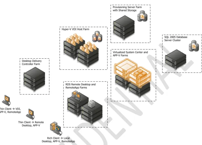
Virtual Desktop Infrastructure
Virtual Desktop Infrastructure (VDI) enables IT staff to deploy desktops in virtual machines on secure and centralized hardware. A centralized and optimized virtual desktop enables users to access and run their desktop and applications wherever they may be, while IT is able to build a more agile and efficient IT infrastructure. Flexible Windows desktop scenarios give organizations the ability to choose the client computing scenarios that best meet the unique needs of their businesses.
Branch Office Regional Office
Central Office / Datacenter
System Center Operations Manager System Center Configuration Manager System Center Virtual Machine Manager System Center Data Protection Manager SQL Server 2005
Figure 2. Microsoft VDI and App-V
When an organization is managing its virtual infrastructure with the same tools it uses to manage its physical assets, it can reduce system complexity and streamline changes made to the overall infrastructure. By using some or all of these technologies together, organizations can provide very flexible solutions to support many user scenarios, including mobile knowledge workers, corporate knowledge workers, contract and offshore developers, contract employees, and end users in branch locations.
Virtualizing the entire computing infrastructure provides tremendous time and cost savings, as well as flexibility benefits. However, attempting to separately manage each layer of the stack and each instance within those layers (such as individual virtual machines) creates a much more complex situation than is necessary. Using different tools for virtualized resources can result in duplicate or competing processes for managing resources, adding complexity to the IT infrastructure. This can undermine the benefits of virtualization. A virtualized world that isn’t well managed can be less reliable and perhaps even more expensive than its non-virtualized counterpart.
Thin Client à Remote Desktop, APP-V Thin Client à VDI,
APP-V, RemoteApp
Rich Client à Local Desktop, APP-V, RemoteApp
Hyper-V VDI Host Farm
Provisioning Server Farm with Shared Storage
Desktop Delivery Controller Farm
RDS Remote Desktop and RemoteApp Farms
Virtualized System Center and APP-V Farms
SQL 2005 Database Server Cluster
Page 11
3.2
Logical Architecture
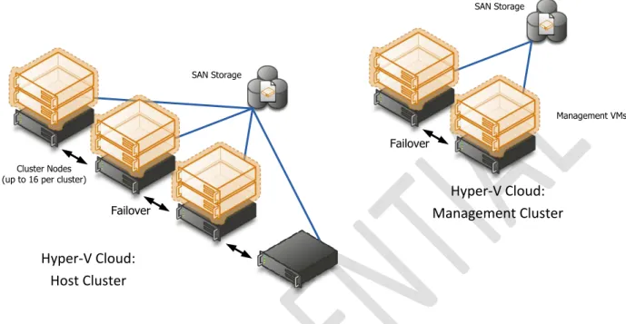
Figure 3. Hyper-V Cloud Fast Track Logical Architecture
A Private Cloud is far more than highly available infrastructure providing computing resources to higher level applications. A fundamental shift of Cloud computing is that of IT moving from server operator to Service Provider. This means a set of services accompany the infrastructure such as reporting, usage metering, self-service provisioning, etc. If these services are unavailable, the Cloud ―service layer‖ is unavailable and we’re back to providing little more than a traditional datacenter. For this reason, when managing 8 compute nodes or greater, high availability must also be provided to the management systems. We achieve this via a management Host cluster typically with 2 nodes.
Mandatory:
>
Dedicated 2-node or more host cluster for V Cloud management (if Hyper-V Cloud is 8 compute-nodes or larger)>
All management products deployed in HA VMs on the management cluster. Oneor more 4 to 16-node host cluster(s) for Hyper-V Cloud tenant VMs
>
A Storage Area Network (SAN) and storage array compatible with WindowsFailover Clustering
>
Gigabit Ethernet or above switched network infrastructure.Note: In well controlled environments with homogeneous workloads (single workload type private cloud) it can be acceptable to host the management stack on the host cluster instead of creating a separate management cluster. This configuration variant provides a way to further consolidate a private cloud environment; however the same general architectural principals that are laid out in this document apply. Specifically it is important to continue to look at the management stack as a separate logical unit which has to be implemented in a highly available fashion. From a practical perspective this means additional infrastructure or reserves will need to be put in place to ensure this. As management and automation is at the heart of a cloud solution, it is critical that the management
SAN Storage
Failover
Hyper-V Cloud:
Management Cluster
Cluster Nodes (up to 16 per cluster)
SAN Storage
Failover
Hyper-V Cloud:
Host Cluster
resource reserves be configured properly. Without proper configuration and reserves, the solution will lose its cloud attributes as potentially no insight, management, metering or new deployment is possible.
Mandatory: If consolidating the management stack onto the host cluster, the following requirements are to be met
>
All management products deployed in HA VMs on the host cluster>
The clustered virtual machines hosting SQL server are guaranteed to run on 2different physical nodes
>
A Storage Area Network (SAN) and storage array compatible with WindowsFailover Clustering
> A separate or dedicated storage path for the management VMs. This can be achieved through physical separate storage connections or for example by means of bandwidth reserves on a shared infrastructure
> Networking: The host cluster needs to provide a strong isolated/independent network for the management stack network traffic to ensure bandwidth
independence from the running workloads. This can be done for example via separate physical network connections or through shared networks with bandwidth guarantees
> Processing/CPU: The management stack VMs need to be configured with the highest possible CPU priority as well as with a reserve of 100% to increase the resource availability for the management VMs
> Memory reserves: The host cluster capacity needs to be defined so that the management stack will have enough memory resources to function even after loss of a cluster node. To improve the probability of the management VMs to be able to restart after failure the VMs should use the highest possible memory priority as well as the dynamic memory feature provided through Windows Server 2008 R2 SP1
3.3
Server Architecture
The host server architecture is a critical component of the virtualized infrastructure, as well as a key variable in the consolidation ratio and cost analysis. The ability of the host server to handle the workload of a large number of consolidation candidates increases the consolidation ratio and helps provide the desired cost benefit.
The system architecture of the host server refers to the general category of the server hardware itself. Examples include rack mounted servers, blade servers, and large symmetric multiprocessor servers (SMP). The primary tenet to consider when selecting system architectures is that each Hyper-V host will contain multiple guests with multiple workloads. Processor, RAM, Storage, and Network capacity are critical, as well as high I/O capacity and low latency. It is critical to ensure that the host server is able to provide the required capacity in each of these categories.
Note: There is a program available for assisting customers in selecting appropriate hardware: Windows Server Catalog contains all servers, storage, and other hardware devices that are certified for Windows Server 2008 R2 (including SP1) and Hyper-V. However, while the Windows Server Catalog lists all the positive tested hardware, it will not help to address sizing or configuration of hardware.
Page 13
3.3.1
Rack Design
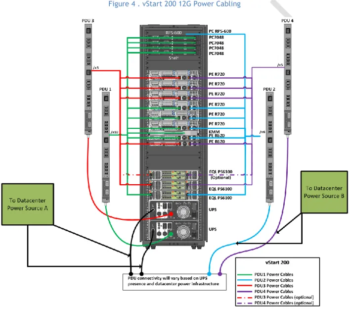
The Dell vStart 200 rack configuration includes four Power Distribution Units (PDU) and two Uninterruptable Power Supplies (UPS). The vStart PDUs are designed to be connected with two different datacenter power sources. The PDUs on the left side are connected to the UPS in the rack, while the PDUs on the right side are connected to another datacenter power source. This design ensures that there is no single point of failure in the power architecture. The redundant architecture is illustrated below.
Figure 4 . vStart 200 12G Power Cabling
Mandatory:
>
The Rack or Blade chassis design must provide redundant power connectivity (multiple PDU capability for racks or multiple hot-swappable power supplied for blade chassis)3.3.2
Server Design
The cloud solution utilizes different model servers for the host and the management cluster. The Dell PowerEdge R720 servers comprise the Host Cluster while the R620 servers are serving as the
Management Cluster hosts.
The Dell PowerEdge R720 server is a 2-socket, 2U rack server designed to excel at running a wide range of applications and virtualization environments for both mid-size and large enterprises. It has highly expandable memory and impressive I/O capabilities. There are six PowerEdge R720 servers included in the vStart configuration. Each is configured with two Intel® Xeon E5-2660 2.2GHz 8-core processors and 96GB memory. Each of the R720 servers also includes a PERC H710 RAID controller along with two 146GB 15K RPM SAS hard drives configured in a RAID 1 for the local storage.
The R620 is a 1U rack server designed with a dual-socket and multi-core processor architecture, a dense memory configuration, and redundant local drives configurable in a RAID. The vStart
configuration for Hyper-V Private Cloud Fast Track requirement includes two PowerEdge R620 servers. Each of the R620s includes one Intel® Xeon® E5- E2609 2.4GHz 4-core Processors and 24GB memory. They also each include a PERC H710 RAID controller configured as RAID 1.
Mandatory:
>
Server with 2 Processor Sockets or more, max of 64 logical processors enabled>
64-bit CPU with AMD Virtualization or Intel Virtualization Technology supportMinimum of 64 GB RAM
>
Min 40 GB local RAID 1 or 10 hard disk space for OS partitionFor more information see Installing Windows Server 2008 R2
http://technet.microsoft.com/en-us/library/dd379511(WS.10).aspx
Recommended: > Use Processors with support for Second Level Address Translation (SLAT) which is also known as EPT on Intel and NPT/RVI on AMD processors.
Table 1. Dell vStart Server Configurations
Component Details
Compute Server Configuration
Server Model PowerEdge R720
Processor (2) x Intel Xeon E5-2660, 2.2Ghz, 8-core, 20M Cache, Turbo, HT
Memory 96 GB (12 x 8 GB, DDR3 dual rank DIMMs, 1333MHz or 1600MHz)
Local storage and controller (1) x PERC H710 Integrated mini RAID controller
(2) x 146GB 15K RPM SAS drives configured in a RAID 1
Management Server Configuration
Page 15
3.3.3
Server Storage Connectivity
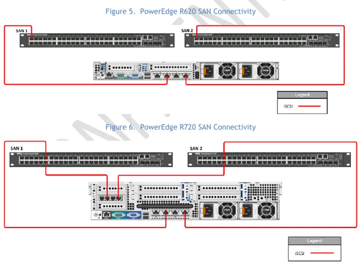
Storage connectivity from the PowerEdge R720 Servers are through four 1Gb NIC ports including two ports provided by the Broadcom BCM5720 rack Network Daughter Card (rNDC) and two ports provided by the add-in Broadcom 5719 PCIe card. Storage connectivity from PowerEdge R620 are through two 1Gb Broadcom BCM5720 rNDC NIC ports. Both R720 and R620 storage connections are distributed to two dedicated PowerConnect switches. These NICs are all dedicated to iSCSI traffic and further segmented logically using Virtual LANs (VLAN) on the PowerConnect switches. NIC connectivity can be seen in the diagrams below.
Figure 5. PowerEdge R620 SAN Connectivity
Figure 6. PowerEdge R720 SAN Connectivity
Processor (1) x Intel Xeon E5-2609, 2.4GHz, 4-core processor, HT
Memory 24 GB (8 x 4 GB, DDR3 dual rank DIMMs, 1333MHz)
Local storage and controller (1) x PERC H710 Integrated mini RAID controller
Mandatory:
>
Internal SATA or SAS controller for direct attached storage unless design is 100% SAN-based including boot from SAN for the Host OS>
If using Fiber Channel SAN, two or more 4 to 8 GFC HBAs>
If using iSCSI, two or more 10 Gb-Ethernet NICs or HBAs>
If using FCOE, two or more 10 Gb-CNAs3.3.4
Server Network Connectivity
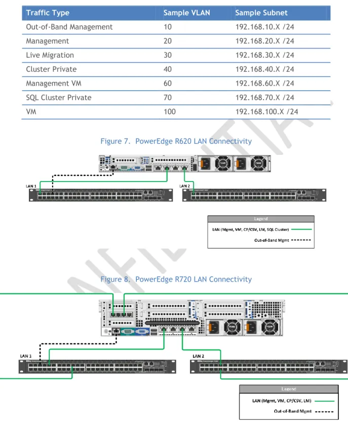
For Network or LAN connectivity, the PowerEdge R720 servers use four 1Gb Ethernet ports including two Broadcom BCM5720 (rNDC) NIC ports and two Broadcom 5719 (Add-in PCIe) NIC ports, while the R620 servers use two 1Gb Broadcom BCM5720 rNDC NIC ports. These connections are distributed to two PowerConnect switches that are configured in a stack. The ports on both the R720 and R620 servers are configured to use VLANs to segregate traffic on the host and provide the segmentation necessary for Hyper-V management, Live Migration (LM), cluster private, VM, and other traffics as described in Table 2. The VLAN configuration used in the vStart configuration is listed in Table 3. Network connectivity for the R620 and R720 are also illustrated below in Figure 7 and 8.
Table 2. Traffic Description
Traffic Type Use
Hypervisor Management
Supports virtualization management traffic and communication between the host servers in the cluster.
Live Migration Supports migration of VMs between the host servers in the cluster.
VM Supports communication between the VMs hosted on the cluster and external systems.
Cluster Private Supports internal cluster network communication between the servers in the cluster.
Out-of-Band Management
Supports configuration and monitoring of the servers through the iDRAC management interface, storage arrays, and network switches.
iSCSI Data Supports iSCSI traffic between the servers and storage array(s). In addition, traffic between the arrays is supported.
Management VM Supports the virtual machine traffic for the management virtual machines. SQL Cluster Private Supports private cluster traffic for the SQL Cluster of the management
Page 17
Table 3. Sample VLAN and subnet configuration
Traffic Type Sample VLAN Sample Subnet
Out-of-Band Management 10 192.168.10.X /24 Management 20 192.168.20.X /24 Live Migration 30 192.168.30.X /24 Cluster Private 40 192.168.40.X /24 Management VM 60 192.168.60.X /24 SQL Cluster Private 70 192.168.70.X /24 VM 100 192.168.100.X /24
Figure 7. PowerEdge R620 LAN Connectivity
Figure 8. PowerEdge R720 LAN Connectivity
Use multiple network adapters and/or multi-port network adapters on each host server. For converged designs, network technologies that provide teaming or virtual NICs can be utilized provided that two or more physical adapters can be teamed for redundancy and multiple virtual NICs and/or VLANs can be
presented to the hosts for traffic segmentation and bandwidth control. The following networks are required:
One network dedicated to the host machine only for management purposes
One network dedicated to the CSV/Cluster Communication network
One network dedicated to the Live Migration network
One or more networks dedicated to the guest virtual machines (use 10 Gbps network adapters
for highest consolidation)
If using iSCSI, one network dedicated to iSCSI with Multipath I/O (MPIO)
The following reference documents the recommended configuration by quantity and type of NIC: Hyper-V: Live Migration Network Configuration Guide http://technet.microsoft.com/en-us/library/ff428137(WS.10).aspx
Mandatory:
>
If using a 10Gb-Ethernet network backbone, each host must have two or more 10Gb-E NICs and the ability to present multiple teamed and/or virtual NICs to the Windows OS.>
If using a Ethernet network backbone, each host must have five1Gb-Ethernet NICs (1 for Mgmt, 1 for CSV, 1 for LM, 2 for VM traffic).
>
If using a 1Gb-Ethrnet network backbone and iSCSI storage, each host most havetwo additional 1Gb-Ethernet NICs for a minimum total of seven.
>
For more configuration information see Hyper-V: Live Migration NetworkConfiguration Guide http://technet.microsoft.com/en-us/library/ff428137(WS.10).aspx.
3.3.5
Server HA and Redundancy
The design of the PowerEdge R620 and R720 servers chosen for the vStart configuration include high availability and redundant features such as redundant fans and power supplies that are distributed to independent power sources. The servers also include RAID configurations to prevent server crashes in the event of single disk failures.
Mandatory:
>
If using rack mounted servers, each server must have redundant power supplies>
If using rack mounted servers, each server must have redundant fans>
If using blade servers, each chassis must have redundant power supplies>
If using blade servers, each chassis must have redundant fans>
If Hyper-V Host system partition uses direct attached storage, each server mustprovide a SAS or SATA RAID capability
3.4
Storage Architecture
The storage design for any virtualization-based solution is a critical element which is typically responsible for a large percentage of the solution’s overall cost, performance, and agility.
Page 19
3.4.1
Storage Options
While many storage options exist, there is product-range sweet-spot for datacenter virtualization. These devices are typically modular and flexible mid and high-end SANs. Modular mid-range SANs are procured independently and can be chained together to provide large capacity and high performance. They are efficient and can grow with the environment as needed but require less up-front investment. Large enterprise environments may have more storage demands and need to serve a larger set of customers and workloads. In this case high-end SANs can provide the highest performance and capacity and typically enable more advanced features such as continuous data availability through technologies like metropolitan-area clustering.
3.4.2
SAN Storage Protocols
(1)
iSCSI vs. FC vs. FCoE
Fiber Channel has historically been the storage protocol of choice for enterprise datacenters for a variety of reasons, including performance and low latency. These considerations have offset Fiber Channel’s typically higher costs. In the last several years, Ethernet’s continually advancing performance from 1 GB/s to 10 GB/s and eventually beyond have led to great interest in storage protocols leveraging the Ethernet transport such as iSCSI and recently, Fiber Channel over Ethernet (FCoE).
A key advantage of the protocols leveraging the Ethernet transport is the ability to use a ―converged‖ network architecture where a single Ethernet infrastructure serves as the transport for both local-area network (LAN) and storage traffic. This can reduce costs in several ways such as the elimination of dedicated Fiber Channel switches and a reduction in cabling which can also be a significant cost in large datacenter environments.
Fiber Channel over Ethernet (FCoE) is an emerging technology, now standardized, which brings the benefits of leveraging an Ethernet transport while retaining the advantages of the Fiber Channel protocol and the ability to leverage Fiber Channel storage arrays.
Several enhancements to standard Ethernet are required for FCoE. This is commonly referred to as Enhanced Ethernet or Data Center Ethernet. These enhancements require Ethernet switches capable of supporting enhanced Ethernet.
For Hyper-V, iSCSI-capable storage provides an advantage in that it is the protocol to be utilized by Hyper-V guest virtual machines for guest clustering.
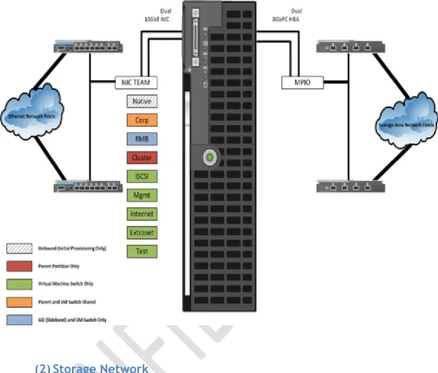
A common practice in large-scale Virtualization deployments is to utilize both Fiber and iSCSI. Fiber provides the Host storage connectivity, and iSCSI is used only by guests that require in-OS iSCSI connectivity such as a guest cluster. In this case, although Ethernet and some Storage I/O will be sharing the same pipe, segregation is achieved by VLANs and QoS can be further applied by the OEM’s networking software.
Figure 9. Example: Blade Server Host Design
(2)
Storage Network
Both iSCSI and FCoE utilize an Ethernet transport for storage networking. This provides another
architecture choice in terms of whether to utilize a dedicated Ethernet network with separate switches, cables, paths etc. or whether to leverage a ―converged‖ network where multiple traffic types are run over the same cabling and infrastructure.
The diagram below illustrates the differences between a traditional architecture on the left with separate Ethernet and Fiber Channel switches, each with redundant paths compared to a converged architecture where both Ethernet and Fiber Channel (via FCoE) utilize the same set of cables while still providing redundant paths. The converged architecture requires fewer switches and cables. In the converged architecture, the switches must be capable of supporting enhanced Ethernet.
Page 21
Figure 10. Converged Network vs. Non-Converged Network
Non-Converged Network Converged Network
Mandatory:
>
Storage solution must provide logical or physical isolation between storage and Ethernet I/O>
If a converged network, QoS must be provided to guarantee storage performance>
Storage solution must provide iSCSI connectivity for guest clustering>
There must be fully redundant, independent paths for storage I/ORecommended:
>
For FCoE, utilize standards-based converged network adapters, switches, and Fiber Channel storage arrays. Ensure that the selected storage arrays also provide iSCSI connectivity over standard Ethernet so that Hyper-V guest clusters can be utilized.>
If using iSCSI or Fiber Channel, ensure that there are dedicated network adapters/HBAs, switches, and paths for the storage traffic.3.4.3
Clustered File Systems (3
rdParty)
The choice of file system to run on top of the storage architecture is another critical design factor. While not strictly required to support Live Migration and other advanced features, use of a clustered file systems or Cluster Shared Volumes (CSV) as part of Windows Server 2008 R2 can provide significant manageability benefits. CSV and clustered file systems enable the use of larger LUNs (logical unit numbers) to store multiple virtual machines while providing the ability for each virtual machine to be live migrated independently. This is enabled by providing all nodes the ability to read and write from the shared LUN at the same time.
LAN SAN A SAN B LAN SAN A SAN B
Ethernet Switches FibreChannel Switches Ethernet Switches FibreChannel Switches Ethernet Switches FibreChannel Switches Datacenter Ethernet Switches (10 Gig-E + FCoE)
The decision of using CSV or a 3rd party solution that is compatible with Hyper-V and Windows Failover
Clustering should be made by carefully weighting the advantages and disadvantages of one vs. the other vs. the actual environment requirements.
3.4.4
Cluster Shared Volumes
Windows Server 2008 R2 includes the first version of Windows Failover Clustering to offer a distributed file access solution. Clustered Shared Volumes (CSV) in R2 is exclusively for use with the Hyper-V role and enables all nodes in the cluster to access the same cluster storage volumes at the same time. This
enhancement eliminates the 1 VM per LUN requirement of previous Hyper-V versions without using a 3rd
party filesystem. CSV uses standard NTFS and has no special hardware requirements, from a functional standpoint if the storage is suitable for Failover Clustering, it is suitable for CSV.
CSV provides not only shared access to the disk, but also storage path I/O fault tolerance (dynamic I/O
redirection). In the event the storage path on one node becomes unavailable, the I/O for that node will be rerouted via Server Message Block (SMB) through another node. There is a performance impact while running this state; it is designed for use as a temporary failover path while the primary dedicated storage path is brought back online. This feature can use any Cluster Communications Network and further increases the need for high-speed networks.
CSV maintains metadata information about the volume access and requires that some I/O operations take place over the cluster communications network. One node in the cluster is designated as the coordinator node and is responsible for these disk operations. Virtual Machines, however, have direct I/O access to the volumes and only use the dedicated storage paths for disk I/O, unless a failure scenario occurs as described above.
(1)
CSV Limits
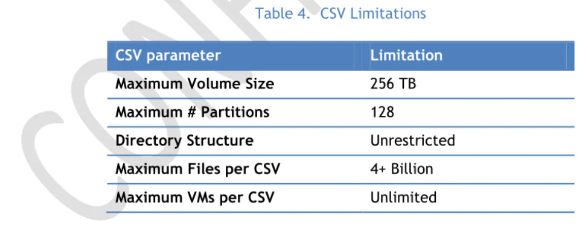
The below limitations are actually imposed by the NTFS file system and are inherited by CSV.
Table 4. CSV Limitations
CSV parameter Limitation
Maximum Volume Size 256 TB
Maximum # Partitions 128
Directory Structure Unrestricted
Maximum Files per CSV 4+ Billion
Maximum VMs per CSV Unlimited
(2)
CSV Requirements
All cluster nodes must use Windows Server 2008 R2
All cluster nodes must use the same drive letter for the system disk
All cluster nodes must be on the same logical network subnet. Virtual LANs (VLANs) arePage 23
NT LAN Manager (NTLM) must be enabled on cluster nodes
SMB must be enabled for each network on each node that will carry CSV clustercommunications
―Client for Microsoft Networks‖ and ―File and Printer Sharing for Microsoft Networks‖ must beenabled in the network adapter’s properties to enable all nodes in the cluster to communicate with the CSV.
The Hyper-V role must be installed on any cluster node that may host a VM(3)
CSV Volume Sizing
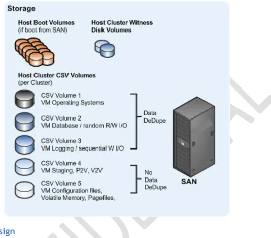
Because all cluster nodes can access all CSV volumes simultaneously, we can now use standard LUN allocation methodologies based on performance and capacity requirements of the expected workloads. Generally speaking, isolating the VM Operating System I/O from the application data I/O is a good start, in addition to application-specific considerations such as segregating database from logging I/O and creating SAN volumes and/or Storage Pools that factor in the I/O profile itself (i.e., random read and write operations vs. sequential write operations).
CSV’s architecture differs from other traditional clustered file systems which frees it from common scalability limitations. As a result, there is no special guidance for scaling the number of Hyper-V Nodes or VMs on a CSV volume. The important thing to keep in mind is that all VM’s virtual disks running on a particular CSV will contend for storage I/O.
Also worth noting is that individual SAN LUNs do not necessarily equate to dedicated disk spindles. A SAN Storage Pool or RAID Array may contain many LUNs. A LUN is simply a logic representation of a disk provisioned from a pool of disks. Therefore, if an enterprise application requires specific storage IOPS or disk response times you must consider all the LUNs in use on that Storage Pool. An application which would require dedicated physical disks where not virtualized may require dedicate Storage Pools and CSV volumes running within a VM.
Recommended:
>
For maximum flexibility, configure LUNs for CSV with a single volume so that 1 LUNequals 1 CSV
>
At least 4 CSVs per Host Cluster are recommended for segregating Operating SystemI/O, Random R/W I/O, Sequential I/O, and other VM-specific data
>
Follow the storage vendor’s recommendations for use with CSVs>
Create a standard size and IOPS profile for each type of CSV LUN to utilize for capacity planning. When additional capacity is needed, provision additional standard CSV LUNs.>
Consider prioritizing the network used for CSV traffic:Designating a Preferred Network for Cluster Shared Volumes Communication
Figure 11. Example: Common CSV design for large Hyper-V Cluster
3.4.5
SAN Design
The vStart configuration uses the iSCSI protocol for the SAN storage fabric. The network supporting the SAN is a 1 Gb Ethernet network with redundancy throughout. Each host in the configuration connects to the SAN though multiple 1 Gb Ethernet ports. The EqualLogic PS6100 arrays used in the vStart provide a high performance and high capacity, cost-effective SAN solution while PowerConnect 1 Gb Ethernet switches are used for SAN connectivity. Details of the components and an overview of the SAN are shown below in Table 5 and Figure 12.
The EqualLogic SAN includes features such as automatic tiering, thin provisioning and a scriptable interface for programmatic control of the arrays. EqualLogic also actively manages iSCSI connections through the EqualLogic Host Integration Tools (HIT) and manages connections to the SAN based upon where data exists on the system.
Table 5. SAN Configurations
Component Details
Storage Configuration
Storage Device EqualLogic PS6100
Drives (2) or (3) x PS6100 24 drive Enclosures (48) or (72) 600 GB 10K RPM SAS Drives RAW Storage Capacity ~28.8TB or ~43.2 TB
Page 25 RAID Configuration RAID 5, 6, 10 or 50
Controller Dual Controllers per Enclosure, each with 4GB memory for PS Series firmware. Each controller provides cache to flash for data protection. (4) 1 Gb Ethernet Ports per controller and (1) dedicated 100Mb Ethernet port for management.
Network Switches PowerConnect 7048 or 6248 Network Redundancy Microsoft MPIO
Device Specific Module EqualLogic Host Integration Tools (HIT)
Host Interface (R720) (2) Broadcom BCM5720 and (2) BCM5719 1GbE ports Host Interface (R620) (2) Broadcom BCM5720 1GbE Ports
Figure 12. EqualLogic PS6100 Connectivity
(1)
High Availability
The SAN’s high availability is taken into consideration from multiple standpoints depending on the device.
The PS6100 includes core high availability features such as redundant fans, controllers, network ports, and power supplies. It also includes hot-swappable components such as controllers, power supplies and hard drives. The controllers are configurable to provide volume high availability through the use of RAID. Each PS6100 is connected to the SAN via ten 1 Gb network connections. Half of each array’s connections are in a standby state and are bound to the inactive controller. Of the active connections, four are dedicated to SAN traffic and one is dedicated to management.
The PowerConnect network switches also use redundant fans and use an optional external Redundant Power Supply (RPS) for redundant power. The PowerConnect switches are further configured with a
LAG for the Inter Switch Link (ISL) resulting in increased bandwidth and link high availability between switches.
Mandatory:
>
Describe the SANs approach to High Availability>
Diagram needed>
A highly-available SAN design should have no single points of failure including: - redundant power from independent PDUs, redundant storage controllers, - redundant target ports of NICs per controller, redundant FC or IP network switches, etc.- data storage redundancy such as with volume mirroring, synchronous or asynchronous replication
(2)
Performance
Storage performance is a complicated mix of drive, interface, controller, cache, protocol, SAN, HBA, driver, and operating system considerations. The overall performance of the storage architecture is typically measured in terms of Maximum Throughput, Maximum IO operations per second (IOPS), and Latency or Response Time. While each of the three factors is important, IOPS and Latency are the most relevant to server virtualization.
Most modern SANs use a combination of high-speed disks, slower-speed disks, and large memory caches. Storage controller cache can improve performance during burst transfers or when the same data is accessed frequently by storing it in the cache memory and can be several orders of magnitude faster than the physical disk I/O. However, it is not a substitute for adequate disk spindles because caches are ineffective at aiding in heavy Write operations.
The EqualLogic family of PS6100 arrays provide a high performance iSCSI SAN through features such as high speed drives, volumes that span multiple arrays thereby improving IOPS as a result of additional spindle count, and a linear scaling peer architecture where performance will scale as a direct relationship to the number of arrays in a group.
Mandatory:
>
Describe the SAN’s performance characteristics(3)
Drive Types
The type of hard drive utilized in the host server or the storage array the host servers will have the most significant impact on the overall storage architecture performance. The critical performance factors for hard disks are the interface architecture (for example, U320 SCSI, SAS, SATA), the rotational speed of the drive (7200, 10k, 15k RPM), and the average latency in milliseconds (ms). Additional factors, such as the cache on the drive, and support for advanced features, such as Native Command Queuing (NCQ), can improve performance. As with the storage connectivity, high IOPS and low latency are more critical than maximum sustained throughput when it comes to host server sizing and guest performance. When selecting drives, this translates into selecting those with the highest rotational speed and lowest latency possible. Utilizing 15k RPM drives over 10k RPM drives can result in up to 35% more IOPS per drive.
Page 27
The base EqualLogic PS6100 array used in the vStart configuration uses 600GB 10K RPM SAS drives. The EqualLogic PS6100 family is also capable of supporting SSD, 15K RPM SAS, and 7K RPM SATA drives in a variety of sizes, however those drives are not part of the base solution.
Mandatory:
>
Describe the SAN’s supported and recommended drive types(4)
RAID Array Design
The RAID type should provide both High Availability and high performance even in the event of disk failures and RAID parity rebuilds. In general, RAID 10 (0+1), or a proprietary hybrid RAID type (i.e. NetApp RAID DP) are recommended for Virtual Machine volumes, RAID 1 is also acceptable for Host Boot Volumes.
The RAID level for EqualLogic PS6100 in the vStart configuration can be configured per customer requirement. The PS6100 is capable of a RAID 5, 6, 10, or 50. RAID 6 provides the greatest amount of disk space while allowing for the failure of up to 4 drives (including hot spares).
Mandatory:
>
Describe the SAN’s RAID Array Design(5)
Multi-Pathing
In all cases, multipathing should be used. Generally storage vendors will build a DSM (device-specific module) on top of Microsoft’s Windows Server 2008 R2 MPIO software. Each DSM and HBA will have its own unique multipathing options, recommended number of connections, etc.
Each host in the configuration uses the Windows Server 2008 R2 MPIO feature and is combined with the EqualLogic Host Integration Toolkit (HIT) to provide the Device Specific Module (DSM) extension into the MPIO module. The HIT makes intelligent decisions to connect each host to the most appropriate iSCSI target from all available targets. The default and preferred MPIO Load Balance Policy is Least Queue Depth.
Mandatory:
>
Describe the SAN’s Multi-pathing solution(6)
Fiber (if FC is used)
(a)
Zoning, Masking, NPIV
Mandatory:
>
Describe the SAN’s Fiber networking, zoning and masking configuration(7)
iSCSI
The vStart configuration uses a dedicated 1GbE iSCSI SAN network with dedicated host network ports and network switches as shown in Figure 13. The SAN network is further isolated through the use of VLANs as noted earlier in Section 3.3.3.
Figure 13. PowerEdge R720 Network Connectivity
Mandatory:
>
The iSCSI SAN must be on an isolated network, both for security andperformance. Any networking standard practice method for achieving this end is acceptable, including:
>
A physically separate, dedicated storage network.>
A physically shared network with the iSCSI SAN running on a private virtual local area network (VLAN). The switch hardware must provide Class or Service (CoS) or Qualify of Service (QoS) guarantees for the private VLAN(a)
Encryption and Authentication
Mandatory:
>
If multiple clusters and/or systems are used on the same SAN, propersegregation or device isolation must be provided. In other words, the storage used by cluster A must be visible only to cluster A, and not to any other cluster, nor to a node from a different cluster.
>
The use of session authentication (Challenge Handshake Authentication Protocol(CHAP) minimum) is suggested. This provides a degree of security as well as segregation.
>
Mutual CHAP or Internet Protocol Security (IPSec) can also be used.(b)
Jumbo Frames
If supported at all points in the iSCSI network, Jumbo Frames can increase throughput by up to 20%. Jumbo frames are supported in Hyper-V at the Host and Guest levels.
Page 29
In the vStart configuration, Jumbo Frames is enabled for all devices of the SAN fabric. This includes the server network interface ports, the network switch interfaces and the EqualLogic interfaces. The EqualLogic ports are configured to use Jumbo Frames by default however the PowerEdge and
PowerConnect devices are not. The PowerEdge server SAN network ports are set to 9000 byte frames by using the Broadcom BACS utility while the PowerConnect switches interfaces are configured for 9216 byte frames by using the command line interface of the switch.
Recommended:
>
Describe the SAN’s implementation of Jumbo Frames(8)
Data De-duplication
Data De-duplication can yield significant storage cost savings in Virtualization environments. Some common considerations are performance hits during the de-duplication cycle, and achieving maximum efficiency by locating similar data types on the same volume, LUN, etc.
No Data-Dedupe is used in the Dell vSTART configuration.
Recommended:
>
Describe the SAN’s use of Data De-duplication and related settings(9)
Thin Provisioning
Particularly in Virtualization environments, thin provisioning is a common practice. This allows for efficient use of the available storage capacity. The LUN and corresponding CSV may grow as needed, typically in an automated fashion to ensure availability of the LUN (auto-grow). However, as storage becomes over-provisioned in this scenario very careful management and capacity planning is critical. Thin provisioning is a feature of the EqualLogic PS6100 array that allows a volume to be presented to the server that is greater than the capacity on disk. The EqualLogic thin provisioning will consume approximately 10% of the stated size and the space will be consumed as data is written to disk. The EqualLogic will alert the administrator via SNMP trap or email when the free space of the volume is less than 60%; however this is a configurable parameter of the EqualLogic group.
Recommended:
>
Describe the SAN’s use of Thin Provisioning and related settings(10)
Volume Cloning
Volume Cloning is another common practice in Virtualization environments. This can be used for both Host and VM volumes dramatically increasing Host installation times and VM provisioning times.
The EqualLogic PS6100 provides volume cloning capabilities to allow volumes to be duplicated bit by bit. An additional feature of the PS6100 is thin cloning where thin clone volumes are matched with
template volume. In the PS Series array architecture, template volumes act as a read-only gold image copy of a volume from which writeable thin clones can be created. The thin clones initially consume little to no storage space on the array and as data is written to the thin clone, only new writes to a thin clone are recorded to storage space thus reducing the amount of storage consumption.