Mixed Shear-Flexural (VM) Hinge
Element and Its Applications
M.T. Kazemi
and S. Erfani
1In the present paper, a mixed, shear-exural (VM) hinge element, with zero or nonzero length, for using in frames, has been introduced, where shear-exural interaction has been considered. The element has the capability of modeling exural yielding, shear yielding and their interaction in frames, subjected to all kinds of monotonic or cyclic loadings. The inelastic shear and exural deformations and tangential stinesses are considered by using the multi-surfaces approach with dissimilar yield surfaces and by a stiness matrix with nonzero o-diagonal components. A new kinematics hardening rule and, also, a new non-associated ow rule are introduced. The mixed hinge element can be used in the arbitrary location of beam-column elements, where shear eect is signicant. The model is examined for some link beams in eccentrically braced steel frames (EBFs) and it is shown that the analytical and experimental results have excellent agreement. Some reduced web section beams are investigated, too. It is shown that the mixed hinge results are in good agreement with the nite element results.
INTRODUCTION
Inelastic analysis and design of structures have made great progress, due to the rapid development of com-puter hardware and software in recent decades [1-4]. The common approach for representing inelastic behavior in a beam-column element is to adopt inelastic hinge formation. A generalized plastic hinge, with zero length, accounting for the interaction of axial, torsional and biaxial bending moments, based on the multi-surfaces plasticity concept, was presented by Powell and Chen [5]. Krenk et al. [6], by using a piecewise lin-earized yield surface and a linear kinematic hardening rule for concentrated hinges, developed a formulation for displacement discontinuities with extension and rotation components. A method for modeling the mem-bers with yielding under combined exure and axial forces in steel frames subjected to earthquake ground motion was presented by Kim and Engelhardt [7]. This method had the capability of modeling plastic axial deformation and changes in axial stiness, based on isotropic and kinematic strain-hardening, dened in axial-exural space. The multi-surface yield concept
*. Corresponding Author, Department of Civil Engineering, Sharif University of Technology, P.O. Box: 11155-9313, Tehran, I.R. Iran.
1. Department of Civil Engineering, Sharif University of Technology, P.O. Box: 11155-9313, Tehran, I.R. Iran.
was used in all the works mentioned above. Liew et al. [8-10] used the two-surface plasticity concept for considering the inelastic interaction between axial force and bending moment, too. The eect of shear force was ignored in all of the above research. El-Tawil and Deierlein [11] investigated two-surface plasticity models in stress-resultant space, based on ber element analysis. Their research was conducted in an axial force-exural moment space and the shear force eect was ignored, too, since the ber element approach is based on a uniaxial stress-strain relationship and the shear force eect is not considered in this approach.
In some cases, shear yielding or combined shear-exural yielding is the governing behavioral mode. For steel beam sections, plastic moment capacity and exural rigidity are aected by shear force [1]. Ricles and Popov [12] developed a formulation for modeling links in eccentrically braced steel frames (EBFs), based on the multi-surface plasticity concept. The link beam has a nonlinear hinge at each end. Each hinge consists of uncoupled shear and exural nonlinear subhinges. Flexural-shear interaction is an important issue in short concrete beams and columns, too. Ricles et al. [13] presented a stress resultant plasticity-based formulation with shear failure criteria and post-shear failure eects, for modeling the response of nonductile reinforced concrete bridge columns subjected to biaxial seismic loading. Kinematic strain hardening and the degradation of elastic unloading stiness under a cyclic
load reversal for both shear and exural eects, were accounted for by using an uncoupled shear-exural hinge approach. A nite element method could also be used for modeling shear-exural inelastic zones. In frame analysis, using this method for the modeling of inelastic zones takes too much time and is not applica-ble, practically. Saritas and Filippou [14] investigated the shear-exural interaction in link beams by using a displacement eld, based on Timoshinko's theory and the integration of biaxial stress-strain relations over several control sections along the beams. Each control section subdivided into several layers. This is a general method for considering the axial, shear and exural interaction in frames. Although the predicted behavior, by using this method, shows good accuracy, because of the need for integration at several points, it takes too much time, the same as in the nite element method.
In the present paper, a mixed VM hinge element, with zero or nonzero length, for using in frames, has been introduced, where shear-exural interaction has been considered. The mixed hinge element has the capability of modeling exural yielding, shear yielding, as well as combined shear-exural yielding. The multi surface concept, with dissimilar yield surfaces and o diagonal components in exibility matrixes, is used. Elastic and inelastic shear distortion and exural rotation are considered. The applicability of the proposed mixed hinge element, for link beams in Eccentrically Braced Frames (EBFs) and reduced web section beams in shear-yielding moment-resistant steel frames, is investigated.
DESCRIPTION OF MIXED HINGE
ELEMENT
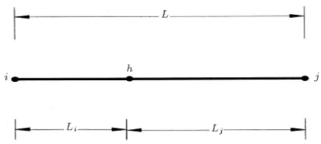
The introduced mixed hinge element includes one inner inelastic combined shear-exural subhinge with zero length and two rigid parts with zero or nonzero lengths on two sides. Geometrical presentation of this element has been shown in Figure 1, whereiandjare the outer nodes andhis the inner subhinge. The inner subhinge has an arbitrary location. The lengths of the two rigid parts areLiandLj, andL=Li+Ljis the total length
of the element. The inelastic zones in the frames could
Figure1. Congurations of the mixed hinge element
with a combined exural-shear subhinge ath.
be modeled by this element. The properties of the mixed hinge element are dened, such that the relative deformations between the two ends should be equal to the relative deformations between the two ends of the inelastic zone, in real condition. The hinge element will be more representative of the inelastic zone if one takes
Las being equal to the length of the inelastic zone.
ELEMENT'S STIFFNESS MATRIX
The mixed hinge element has two end nodes and, in a two-dimensional space, has six degrees of freedom. For denition of these degrees of freedom, a local coordinate system dependent on the element is used. If the element's end forces and displacements are described as
P
andU
, respectively, it can be written, as follows:P
=P
iP
jT; (1)
U
=U
iU
jT; (2)
where,
P
i,P
j,U
i andU
j are nodal forces anddisplacements at i and j, respectively (see Figure 2). If the element's internal forces and deformations in the inner subhinge node are shown as
P
h andU
h,respectively (see Figure 3), then, one could write:
P
=AP
h; (3)U
h=A
TU; (4)where,
A
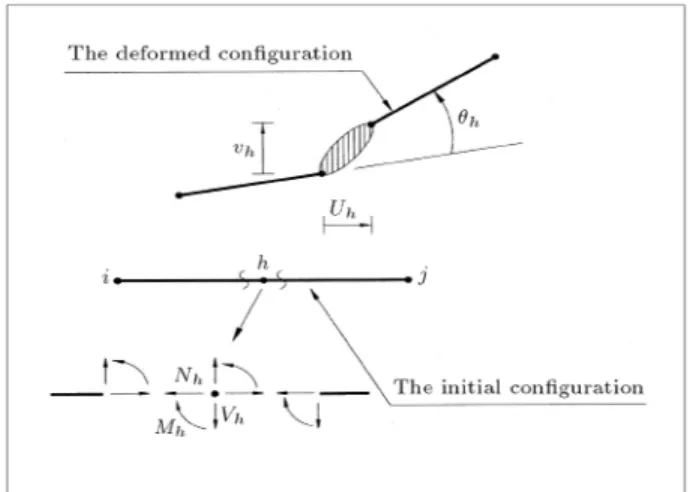
is the transformation matrix and its compo-nents are dependent on lengths of rigid parts of the element. It is assumed that no loads and masses are assigned to the subhinge and to the rigid parts, except at the end nodes. It is noted that the deformations are assumed to be small and, then, the initial congurationFigure2. The mixed hinge element's end forces and
Figure3. The mixed hinge element's internal forces and
deformations.
is used for equilibrium and compatibility considera-tions. Figure 3 presents the initial and deformed conguration of the mixed hinge element.
If the rates of forces and deformations in the element's inner subhinge are shown as
_P
h and_U
h,respectively, then, one could write:
_P
h=K
h_U
h; (5)_U
h=F
h_P
h; (6)where,
K
h andF
h are the tangential stiness andexibility matrixes of the subhinge, respectively. Since all of the degrees of freedom in the inner subhinge are independent of each other, both
K
h andF
h areinvertible and inverse to each other.
From Equations 3 to 5, it can be resulted:
_P
=A _P
h=AK
h_U
h=AK
hA
T_U
; (7)where,
_P
and_U
are the element's rate of forces and deformations, respectively. Therefore, for the mixed hinge element stiness, one could reach:K
=AK
hA
T =AF
1h
A
T; (8)where,
K
is the element's stiness matrix and so:_P
=K _U
: (9)INNER SUBHINGE STIFFNESS AND
LOADING-UNLOADING CRITERIA
The components of elastic-plastic tangential stiness or exibility matrixes may depend on applied loads or deformations and loading history. The present paper focuses on shear-exural interaction and ignores the eects of axial force in nonlinear formulation. Thus, the components corresponding to the axial deformation in the stiness or exibility matrix remain elastic and
constant. By assuming rate independency, in a two dimensional space, Equation 5 can be written as:
8 < :
_
N_h
V_h
Mh 9 = ; = 2 6 6 6 6 4 dNh
duh 0 0
0 @Vh
@h
@Vh
@h
0 @Mh
@h @Mh @h 3 7 7 7 7 5 8 < : _ uh _ _h h 9 = ; : (10)
The components of the tangential stiness matrix,
K
h,are not dened directly. By calculating the inner subhinge's tangential exibility matrix,
F
h, and theninversing it, the tangential stiness matrix,
K
h, isob-tained. For small deformation,
F
h can be decomposedas:
F
h=F
eh+F
ph; (11)where,
F
eh andF
ph are the inner subhinge's elastic and plastic tangential exibility matrixes, respectively. The results of experimental studies or numerical analyses of any kind of real hinge zone can be used for determina-tion ofF
ph. In some studies [5-13], associated ow rule has been used for the calculation ofF
ph, as follows:F
ph=nn
Tn
TK
pn
; (12)where,
n
is the outward normal unit vector from the yield surface at the point of action andK
p is adiagonal plastic stiness matrix from the individual action-deformation relationship for the inner subhinge, as follows:
K
p=2 4
0 0 0
0 Kp 0
0 0 Kpm
3
5: (13)
By using Equation 12, ow rule will stay associated and so the plastic deformation vector will always be normal to the yield surface. In the work of Ricles and Popov [12], where shear-exural interaction was studied, it has been assumed that yield surfaces are rectangular. As shown in Figure 4, by using the associated ow rule, at any point of line AB,
F
ph is, as follows:F
ph=2 4
0 0 0
0 0 0
0 0 1=Kpm
3
5: (14)
And, at any point of line CD, one has:
F
ph=2 4
0 0 0
0 1=Kp 0
0 0 0
3
5: (15)
So, for the two close points of B and C of which both are very close to the rectangular corner, two quite
Figure4. Rectangular yield surface in the shear-exural
space.
dierent plastic deformations will be resulted. In the present paper, instead of using Equation 12, a dierent denition for
F
ph is used, as follows:F
ph=m
2V
F
pV +m
2M
F
pM; (16)in which
F
pV andF
pM are the exibility matrixes related to the pure shear and the pure exural loadings, respectively. mV and mM are the components ofm
vector in VM space, which is the unit location vector of the action point. As shown in Figure 4, for the points close to the corner,
m
,F
ph and plastic deformations vary smoothly. With this denition, the ow rule will not be associated.In some non-associated cases, the loading-unloading criteria may fail to dierentiate between plastic ow and elastic unloading. To overcome this complexity, the loading-unloading criteria need to be dened more precisely. Suppose the action point lies on a yield surface and the deformation increment is given as
_U
h. First, by usingK
h = (F
eh) 1, the action rate,_P
h, is predicted. If 1 =n
T
_P
h < 0, the unloadingcondition exists. For corner points, the unloading condition for both
n
B andn
C should be satised. If1
0, by calculating
K
h = (F
eh+F
p
h) 1, the new
action rate,
_P
h, is obtained. With the new_P
h, if2 =
n
T
_P
h > 0, the plastic loading condition willgovern. For corner points, the plastic loading condition needs for only one of
n
Born
Cto be satised. If20,
the stiness matrix will be adjusted to:
K
h= (F
eh+F
ph) 1 21
(
F
eh) 1: (17)By using the adjusted stiness and calculating the new action rate,
_P
h, the normality condition,n
T_P
h = 0,will result and the natural loading condition will occur.
n
B andn
C are the unit normal vectors, at points Band C, which are very close to the corner but on two dierent surfaces (see Figure 4).
YIELD SURFACES
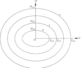
For considering the interaction between shear force and exure, the multi surface concept in shear-exural, VM space, is used (see Figure 5). This concept, which was originally dened in stress space [15,16], was adapted with some modications for the resultant forces space [5-13]. Some of the important aspects and basic assumptions of this concept are, as follows: 1. The yield surfaces are convex;
2. The yield surfaces can be changed in size and translated, but have to be tangential with each other and cannot be intersected;
3. If the action point is internal of the initial yield surface, the behavior will be elastic and, if on each of the surfaces, the behavior will be elastoplastic; 4. In tangency of several yield surfaces, the outer
surface properties dene the current behavior. Similarity of yield surfaces is a main assumption in most works, except in some recent studies [12]. The similarity assumption has been used to have parallel directions for the corresponding points on the yield surfaces and, as a result, when the yield surfaces closely approach each other, they will not intersect and, asymptotically, will be tangential to each other. If it is assumed, in shear-exural space, that yield surface, i, is similar to yield surface,j, then, one will have:
Vyi
Vyj = MMyjyi; (18)
where, Vyi,Vyj, Myi andMyj are the points oni and
jyield surfaces for the pure shear and bending loading (see Figure 5). This is not a realistic assumption, generally.
Figure5. Typical yield surfaces in the multi-surfaces
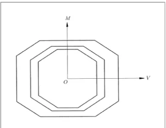
Ricles and Popov [12] overcame this problem by choosing a rectangular yield surface with dierent ratios of length to width, but, it is noted that, with the use of rectangular yield surfaces, the interaction of shear-bending is ignored, practically. In the present research, by considering piecewise dissimilar yield sur-faces, as shown in Figure 6, the above shortcoming is resolved and shear-exural interaction is considered, more realistically. The yield surfaces may have polyg-onal shapes. For preventing the intersection of yield surfaces, the corresponding sides of all yield surfaces should be parallel to each other and the length of any side of any yield surface should be smaller than the length of the corresponding side of the outer yield surface.
HARDENING RULE
The hardening rule denes the manner by which the yield surface changes. For all of the surfaces, trans-lation (kinematic hardening) and, also, change in size (isotropic hardening), are permitted, except for the last yield surface. The last yield surface is assumed to have a change in size, only because the nal plastic capacity of a section is constant. The same as in some recent works [5-13], the element formulation is based on combined kinematic and isotropic hardening for the shear force, and only kinematic hardening for exure. On this basis, theith yield function is written, as follows:
i(
P
h i;Hi) = 0; (19)where,
P
his the action vector of the subhinge. i andHi are theith yield function center and its expansion
parameter, respectively.
For developing the shear isotropic hardening, the
Figure6. Typical piecewise dissimilar yield surfaces used
for the mixed hinge element.
following is adopted [17]:
Vyie=HiVyi; (20)
where,VyiandVyieare the initial and developed values
of the shear force at ith yielding, respectively. Hi is
written as:
Hi = 1 +C1[1 C2exp( vhp)]; (21)
where:
vhp=
Z jdv
p
hj; (22)
andC1 andC2 are material constants.
Various kinematic hardening rules were used in most recent works [7,12,13]. In this paper, a new kinematic hardening rule is introduced. As seen in Figure 7, it is assumed that the action location is on the
ith yield surface and plastic loading is occurring. The rate of theith yield surface translation,
_
i, is assumedas being:
_
i= (
P
hi+1P
hi)_
; (23)
where,
P
hi+1 is the intersection point between thedirection of the action rate,
_P
h, and the (i+1)th yieldsurface, and
P
hi is the conjugate point ofP
hi+1 onthe ith yield surface. By this denition, when the action point,
P
h, approaches closer to the (i+ 1)thyield surface, the ith yield surface moves, such that the two points on the ith yield surface,
P
hi andP
h,approach closer to each other and coincide with
P
hi+1,asymptotically. It shows that the inner moving yield surface may be tangential to the outer yield surface at the contact point and they never intersect.
To calculate
_
, the plastic loading condition isused: _
i= 0: (24)
Figure 7. Action point and corresponding points on two
Hence:
@i
@
P
h_P
h+@@ii_
i+
@i
@HiH_i= 0: (25)
And, since one has:
@i
@
P
h = @@ii; (26)
so, Equation 25 can be written as:
@i
@
P
h_P
h= @@P
ih_
i@i
@HiH_i: (27)
After pre-multiplying both sides of Equation 23 by@
i
@Ph, one reaches the following:
@i
@
P
h_
i=@i
@
P
h(P
hi+1P
hi)_
: (28)
Comparing the last two equations results in the follow-ing:
@i
@
P
h_P
h= @@P
ih(P
hi+1P
hi) _ @i
@HiH_i; (29)
or: _
= @i
@P h
_P
h+@i @Hi _ Hi @i @P h(
P
hi+1
P
hi): (30)
By substituting Equation 30 in Equation 23, _i can be
determined, as follows:
_
i=
@i
@P h
_P
h+@i @Hi _ Hi @i @P h(
P
hi+1
P
hi)(P
hi+1P
hi); (31)_
i is the parameter of the translation criteria for the
ith yield surface, due to loading.
COMPARISON WITH SOME EXISTING
TEST RESULTS
In this part, the capability of the proposed mixed hinge element for link beams in EBFs is investigated. For the rst example, the medium link beam tested by Kasai and Popov [18] and analyzed by Ricles and Popov [12], is investigated. The link element consists of a W810
link beam, with a length of L = 368 mm. The shear capacity of the element's section isVp= 205:5 kN and
the exural capacity isMp= 56:3 kN-m. The element
was subjected to cyclically symmetric deformations. Regarding the end conditions of the element in the laboratory, the stiness of the right end was more than that of the left. So, shear and exural yielding in the element has been started from the right end with a redistribution of exural end moments during yielding. For modeling by the mixed hinge element, the location
of the inner subhinge is assumed to be at the right end (Li =L, Lj = 0). For C1 and C2 parameters of
Equation 21, based on regression analysis, the values of 0.8 and 10 were proposed, respectively [17]. In the present study, with some trial, the values of 0.35 and 15 are used for C1 and C2, respectively. The yield
surfaces used for this example have been shown in Figure 8. These shapes, chosen for yield surface, are based on a set of experimental results presented by Kasai and Popov [18]. The exibility matrix for the inner subhinge is assumed to be as follows:
F
h=2 6 6 6 6 6 4 L
EA 0 0
0 1
k1
L3 3EI +
1 k2 L GAs 1 k3 L2 2EI 0 1 k3 L2 2EI 1 k4 L EI 3 7 7 7 7 7 5 ; (32)
where,E andGare Young's modulus and the modulus of rigidity of the section material and A, I and As
are area, moment of inertia and shear area of the link section, respectively. k1, k2, k3 and k4 in the above
matrix, are the constants which represent the stiness ratio between each two yield surfaces for two conditions of pure shear and bending loading. In the mentioned works [12,17], the stiness ratios between each two yield points in the shear-deection or exural-rotation diagrams, were assumed to be 0.03, 0.015 and 0.002, as seen in Figure 9. In the present work, regarding the dierence between the failure modes of pure shear and exural loading and with some trial, thek1,k2,k3
andk4ratios have been selected, as shown in Tables 1
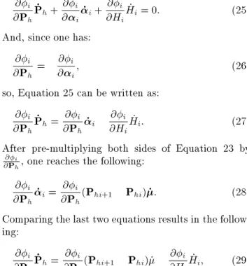
and 2. The experimental [18] and analytical results are compared in Figure 10, where, horizontal axes (Dis.) indicate the relative shear deformation between the two ends of the link beam. As shown, the mixed hinge
Figure8. Yield surfaces of mixed hinge element used for
Figure9. Typical multilinear load-deformation relation.
Figure10. Experimental measurements and analytical
results of the medium length link beam.
results are in good agreement with the test results. The manner of expansion and translation of yield surfaces in the mixed hinge are shown in Figure 11. As seen, yielding reached the shear-exural interaction zone, rstly. Then, the behavior of the element was controlled by the exural capacity of the element.
For the second example, the shortest link element
Table1. Constants of exibility matrixes for pure shear
loading of the link beams.
Between YieldSurfaces
k 1
k 2
k 3
k 4 0and 1 0.060 0.060 0.060 0.060 1and 2 0.030 0.030 0.030 0.030 2and 3 0.010 0.010 0.010 0.010 Table 2. Constants of exibility matrixes for pure
exural loading of the link beams.
Between YieldSurfaces
k 1
k 2
k 3
k 4 0and 1 0.030 0.300 0.030 0.030 1and 2 0.015 0.150 0.015 0.015 2and 3 0.002 0.020 0.002 0.002
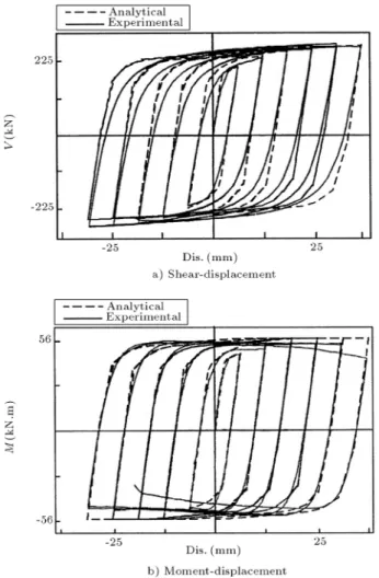
tested by Kasai and Popov [18] is investigated. The length of this element is L = 292 mm and its other congurations are the same as in the foregoing example. The failure mode of this element is dierent and shear yielding controlled the behavior of the element. All of the parameters used for modeling by the mixed hinge element are the same as in the foregoing example. The experimental [18] and analytical results are compared in Figure 12, which shows that the analytical and experimental results are in excellent agreement.
Although the length and the failure modes of the two previous examples are dierent, the developed mixed hinge element explained the behavior of both links, with acceptable accuracy.
Figure 11. The yield surfaces expansion and translation
Figure12. Experimental measurements and analytical
results of the short length link beam.
APPLICATION OF THE MODEL ON
REDUCED WEB SECTION BEAMS
Reduced web section beams in shear-yielding moment-resistant steel frames have been investigated re-cently [19]. These beams are used in steel frames for earthquake energy dissipation by shear yielding of their reduced webs. In this part, the modeling of the reduced web zones of these beams is examined by using the mixed VM hinge element. Three reduced web section beams, with equal sections but dierent span lengths, as shown in Figure 13, are investigated. The beams consist of W2168 (A = 13131 mm
2,
I = 625770000 mm4 and A
s= 5900 mm2), with span
lengths of 2520, 3780 and 6720 mm and two circular holes at the ends. The diameter of each hole is 420 mm and its center is located 630 mm from the closer end. Multi-linear kinematic hardening plasticity is assumed
Figure13. Geometrical conguration of the reduced web
section beams.
for the material of the beams, with Fy = 360 MPa,
Fu = 500 MPa,E = 200 GPa, H = 0:005E = 1 GPa
and = 0:3. Where Fy and Fu are the yield and
ultimate stress,E andH are the initial and post yield modulus of elasticity and is the Poisson ratio. All of the beams are subjected to cyclically symmetric relative displacements between two ends, as shown in Figure 14. The analysis is done statically and rota-tional freedom at both ends is prevented. The beams are analyzed with a nite element program at the rst stage. In these analyses, eight-node solid elements with nonlinear material behavior, in accordance with von-Mises criteria, are used. Regarding beam symmetry, half the beams are modeled. The maximum element dimension is 50 mm. The beams are reanalyzed by using the proposed model at the second stage. In these analyses the two mixed hinge elements, with a length ofL= 1260 mm, are used at both ends of the beams. Location of the subhinge is assumed to be in the middle of the hinge element (Li =Lj = 630 mm), coincident
to the center of the hole, as shown in Figure 15. The hinge element, analyzed between the two for pure shear and pure exural, separately, by using the nite element method and the mixed hinge element property, is obtained. The resulted yield surfaces are shown in Figure 16. The inner subhinge exibility matrixes in
Figure14. Displacement history applied to the reduced
Figure15. Modeling of the reduced web section beams
with a beam and two mixed hinge elements.
Figure16. Yield surfaces used in the mixed hinge
element for modeling of the reduced web section beams.
consecutive yield surfaces are assumed to be, as follows:
F
h=2 4
1 0 0
0 1 L=2
0 0 1
3 5 2
6 6 6 6 6 4 1
r0
L
EA 0 0
0 1
k1 1
r1
L3 3EI +
1
k2 1
r2
L GAs
1
k3 1
r3
L2 2EI
0 1
k3 1
r3
L2 2EI
1
k4 1
r4
L EI
3 7 7 7 7 7 5 2
4
1 0 0
0 1 0
0 L=2 1
3 5:
(33) The k1, k2, k3 and k4 hardening coecients are
selected, as seen in Table 3 and equivalent eective sti-ness factors, obtained from the nite element analysis, are r0 = 0:883, r1 = 0:983, r2 = 0:592, r3 = 0:977
and r4 = 0:977. Since isotropic hardening is ignored,
then, one hasC1 =C2 = 0 (Equation 21). The nite
element model and the mixed hinge element results are compared in Figures 17 to 19. As shown, the mixed hinge results are in fairly suitable agreement with the nite element results. The manner of translation of yield surfaces in the mixed hinge modeling is shown in Figures 20 to 22. In these gures, shear and exural
Table3. Constants of exibility matrixes for pure shear
and pure exural loadings of the reduced web section beams.
Between YieldSurfaces
Pure Shear Pure Flexural
0and 1 0.300 0.333
1and 2 0.038 0.033
2and 3 0.005 0.004
Figure 17. The comparison between nite element
analysis and mixed hinge element results of the reduced web section beam with span ofS= 2520 mm.
moment are the internal forces in the location of the inner subhinge (hole center), and displacement is the relative transverse displacements between the two ends of the beam. As shown in the rst model, the shear ca-pacity is governed and, in the third model, the exural capacity controls the behavior of the beam. However, in the second beam, the action point is located at the shear-exural interaction zone. Although, in the three beams, the failure modes are dierent, the results of the presented mixed hinge element modeling have good accuracy.
It is observed that using an octahedral yield surface instead of a rectangular yield surface is more ecient, especially for the reduced web section beam with a medium span (S= 3780 mm), where the action point is located on the oblique line of the octahedral yield surface (see Figure 21). In Figure 23, the results
Figure18. The comparison between nite element
analysis and mixed hinge element results of the reduced web section beam with span ofS= 3780 mm.
Figure19. Shear-displacement and
moment-displacement comparison between nite element analysis and mixed hinge element results of the reduced web section beam with lengthS= 6720 mm.
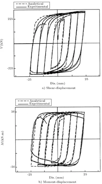
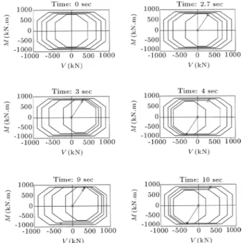
Figure20. Translation history of yield surfaces for the
mixed hinge element of the reduced web section beam with span ofS= 2520 mm.
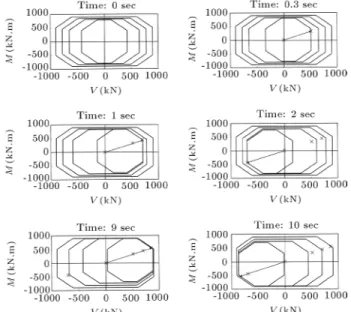
Figure21. Translation history of yield surfaces for the
mixed hinge element of the reduced web section beam with span ofS= 3780 mm.
of the reduced web section beam with medium span, using octahedral and rectangular yield surfaces, are compared with the nite element result. As seen, the octahedral yield surface model result is more realistic and closer to the nite element result.
The requirement of using the proposed element, considering shear-exural interaction, is claried in Figure 24. In this gure, the exural moment at the inner subhinge, the center of the web hole, is presented against the monotonic rotation of the inner subhinge and pure exural loading is compared with
shear-Figure22. Translation history of yield surfaces for the
mixed hinge element of the reduced web section beam with span ofS= 6720 mm.
Figure23. Comparison of the nite element analysis
(solid line) with the mixed hinge element analyses using the octahedral yield surfaces (dot line) and the
rectangular yield surfaces (dashed line).
Figure 24. Shear force eect on moment-rotation
relationship for the three reduced web section beams with dierent spans.
exural loading in three reduced web section beams. It is observed that the pure exural loading result is very dierent from the other cases and the eect of shear force on the reduction of the exural capacity of the element increases by reducing the beam span length.
CONCLUSIONS
In this paper, a new shear-exural mixed hinge element was developed for consideration of the interaction be-tween internal forces, for two dimensional frame anal-yses. The hinge element could have a nonzero length to model plastic zones in the beams. A multi-surfaces concept was used for the modeling of the mixed hinge element, by proposing dissimilar yield surfaces and suggesting o-diagonal members in exibility matrixes. A new procedure for plastic loading on yield surfaces suggested insuring a smooth variation of the hinge exibility matrix. Also, a new kinematic hardening rule was introduced to prevent any intersection of the dissimilar yield surfaces. The mixed hinge element was examined for some link beams in EBFs and reduced web section beams in shear-yielding moment-resistant steel frames. The proposed analytical results were compared with existing experimental results (for link beams) and nite element results (for reduced web section beams) and close agreements were observed.
REFERENCES
1. Horne, M.R. and Morris, L.J., Plastic Design of Low-Rise Frames, Collins, London, Constrado Monographs (1981).
2. Chen, W.F. and Lui, E.M., Stability Design of Steel Frames, Boca Raton, Fl: CRC Press (1991).
3. Mazzolani, F.M. and Piluso, V.,Theory and Design of Seismic Resistant Steel Frames, London, E & FN Spon (1996).
Structures, John Wiley & Sons, LTD, New York, USA (2002).
5. Powell, G.H. and Chen, P.F.S. \3D beam-column element with generalized plastic hinges", ASCE J. of Eng. Mech.,112(7), pp 627-641 (1986).
6. Krenk, S., Vissing, S. and Vissing-J., C. \A nite step updating method for elastoplastic analysis of frames",
ASCE J. of Eng. Mech.,119(12), pp 2478-2495 (1993).
7. Kim, K.D. and Engelhardt, M.D. \Beam-column el-ement for nonlinear seismic analysis of steel frames",
ASCE J. of Struct. Eng.,126(8), pp 916-925 (2000).
8. Liew, J.Y.R. and Tang, L.K. \Advanced plastic hinge analysis for the design of tubular space frames",Eng. Struct.,22(7), pp 769-783 (2000).
9. Liew, J.Y.R., Chen, W.F. and Chen, H. \Advanced inelastic analysis of frame",J. of Construct. Steel Res.,
55(3), pp 245-265 (2000).
10. Liew, J.Y.R., Chen, H., Shanmugam, N.E. and Chen, W.F. \Improved nonlinear plastic hinge analysis of space frame structures",Eng. Struct.,22(10), pp
1324-1328 (2000).
11. El-Tawil, S. and Deierlein, G.G. \Stress-resultant plas-ticity for frame structures",ASCE J. of Eng. Mech.,
124(12), pp 1360-1370 (1998).
12. Ricles, J.M. and Popov, E.P. \Inelastic link element for EBF seismic analysis", ASCE J. of Struct. Eng.,
120(2), pp 441-463 (1994).
13. Ricles, J.M., Yang, Y.S. and Priestley, M.J.N. \Mod-eling nonductile R/C columns for seismic analysis of bridges",ASCE J. of Struct. Eng.,124(4), pp 415-424
(1995).
14. Saritas, A. and Filippou, F.C. \Modeling of shear-yielding members for seismic energy dissipation",13th World Conference on Earthquake Engineering, Paper No. 1799 (2004).
15. Khan, A.S. and Huang, S., Continuum Theory of Plasticity, John Wiley & Sons. Inc., New York, USA (1995).
16. Mroz, Z. \An attempt to describe the behavior of met-als under cyclic loads using a more general workhard-ening model", Acta Mechanica, 7(2-3), pp 199-212
(1969).
17. Ramadan, T. and Ghobarah, A. \Analytical model for shear link behavior", ASCE J. of Struct. Eng.,
121(11), pp 1574-1580 (1995).
18. Kasai, K.S.M. and Popov, E.P. \General behavior WF steel shear link beams", ASCE J. of Struct. Eng.,
12(2), pp 362-382 (1986).
19. Halterman, A. and Aschheim, M. \Analytical studies of shear-yielding moment-resistant steel frames",12th World Conference on Earthquake Engineering, Paper No. 1544 (2000).