Sharif University of Technology
Scientia IranicaTransactions B: Mechanical Engineering www.scientiairanica.com
The eect of angle of attack on limit cycle oscillations
for high-aspect-ratio wings
M. Dardel
, K. Eskandary, M.H. Pashaei and A.H. Kiaeian Moosavi
Department of Mechanical Engineering, Babol Nooshirvani University of Technology, Shariati Street, Babol, P.O. Box 484, Postal Code: 47148-71167, Mazandaran, Iran.
Received 12 December 2011; received in revised form 28 April 2013; accepted 9 September 2013
KEYWORDS High aspect ratio wing;
Flap-lag and torsion; Angle of attack; Flutter;
Limit cycle oscillation.
Abstract.In this study, the eect of the angle of attack on the aeroelastic characteristics of high aspect ratio wing models with structural nonlinearities in unsteady subsonic aerodynamic ows is investigated. The studied wing model is a cantilever wing with ag, lag and torsion vibrations and with large deection capability, in accordance with the Hodges-Dowell wing model. An unsteady low speed incompressible air ow is assumed to include the ow time lags. Variations of the limit cycle amplitudes and frequency with free stream velocity at dierent angle of attacks are carefully studied. For the considered model, the angle of attack has little eect on utter velocity but its eect on limit cycle amplitudes and frequency is considerable. This study shows that the limit cycle amplitudes are very sensitive to variations in angles of attack.
© 2014 Sharif University of Technology. All rights reserved.
1. Introduction
Helicopter blades and some models of aircraft have long wings with great exibility in which nonlinear deformations have important roles to play. Great deections of these structures are describable by struc-tural nonlinear modeling. The presence of nonlinear structural factors with aerodynamic forces leads to unsuitable aeroelastic phenomena such as limit cycles. Therefore, careful review and understanding of these phenomena in aeroelastic systems are vital.
Modeling of long wings has been undertaken by several researchers, some of which have been mentioned here. Hodges and Dowell developed the equations of motion by two complementary methods; Hamilton's principle and the Newtonian method [1]. Tang and Dowell constructed an experimental high-aspect-ratio
*. Corresponding author.
E-mail addresses: [email protected] (M. Dardel); keivan.eskandary yahoo.com (K. Eskandary); mpashaei nit.ac.ir (M.H. Pashaei); a kmoosavi yahoo.com (A.H. Kiaeian Moosavi)
wing aeroelastic model with a slender body at the tip. They investigated the utter and Limit-Cycle Oscilla-tions (LCO) of a wing in a wind-tunnel test [2]. Tang and Dowell presented a nonlinear response analysis of a high-aspect-ratio wing aeroelastic model excited by gust loads, theoretically, and examined it in a wind-tunnel [3]. Patil et al. described a formulation for aeroelastic analysis of aircraft with high-aspect-ratio wings [4]. Malatkar explored the impact of kinematic structural nonlinearities on the dynamics of a highly deformable cantilevered wing [5]. Nichkawde presented a study of the nonlinear vibrations of metallic cantilever beams and plates subjected to transverse harmonic excitations [6]. Tang, Henry and Dowell studied the eects of a steady angle of attack on the nonlinear aeroelastic response of a delta wing model to a periodic gust [7]. Gordnier and Visbal perform relevant aeroelastic analyses for a delta wing at an angle of attack, and a computational technique capable of addressing both complex nonlinear aerodynamics and nonlinear structural features is presented [8]. Tang and Dowell presented a paper built on previous work concerned with the development of a comprehensive
velocity sensitivity model for continuous scanning laser vibrometry [9]. Soltani et al. [10] have examined the ow eld over a swept wing under various conditions. Ghadimi et al. [11] investigated the thermal utter characteristics of an imperfect cantilever plate under aerodynamic loads. Davari et al. [12] studied the eects of various wings on the tail ow eld by measuring the tail pressure distribution. Dardel and Bakhtiari-nejad [13] presented a static output feedback controller for aeroelastic control of a cantilevered rectangular wing in low subsonic ow. Jian and Jinwu considered the nonlinear aeroelastic response of high-aspect-ratio exible wings [14]. They investigated the dynamic stall in accordance with the ONERA wing model and investigated the eect of aerodynamics drag on utter and limit cycle amplitudes. Qiang et al. investigated aeroelastic modeling and calculation for high aspect ratio composite wings with dierent forward swept angles and skin ply orientation [15]. Gordnier et al. developed a high-order (up to 6th order) Navier-Stokes solver coupled with a structural solver that de-composes the equations of three-dimensional elasticity into cross-sectional (small-deformation and spanwise), large-deformation analyses for slender wings [16]. The resulting high-delity aeroelastic solver is applied to the investigation of rigid, moderately exible and highly exible rectangular wings undergoing a pure plunging motion. Xie et al. developed a rapid and ecient method for static aeroelastic analysis of a ex-ible slender wing when considering structural geometric nonlinearity [17]. A non-planar vortex lattice method herein is used to compute the non-planar aerodynamics of exible wings with large deformation. The nite element method is introduced for structural nonlinear statics analysis.
In this work, the aeroelastic behavior of a Hodges-Dowell wing model with an incompressible unsteady aerodynamic model is investigated. A brief descrip-tion of the Dowell-Hodges beam is given here. The theory is intended for application to long, straight, slender, homogeneous, isotropic beams with moderate displacements, and is accurate to second order, based on the restriction that squares of bending slopes, twist t=L, and c=L, are small with respect to unity. Radial non-uniformities (mass, stiness, twist, etc.), chord-wise osets of the mass centroid and tension axes from the elastic axis, and the warp of the cross section are included. Other more specialized details are not considered, such as blade root feathering exibility, torque oset, blade sweep, and curvature, nor are con-gurations considered in which the feathering bearing is replaced with a torsionally exible strap [1]. In in-compressible unsteady aerodynamic models the eects of wakes, compressibility and viscosity are ignored. Determination of utter and divergence velocities and clarication of limit cycle amplitudes are investigated
in the current study. Eects of changing mass ratio and the distance between the elastic axis and center of mass and other parameters, are carefully examined in aeroelastic properties. This study is done for dierent models of wing section to evaluate the inuence of mass and inertia eects on limit cycle amplitude and utter velocity. The eects of structural damping are considered in structural modeling. The eect of initial angle of attack on limit cycle amplitude is specied. 2. Aeroelastic equations
2.1. Structural equations of motions
In this section, a brief description of structural equa-tions of motion of a wing model, based on the Hodges-Dowell wing model, is presented. A Hodges-Hodges-Dowell wing model presents double bending and torsional vibrations. Hodges-Dowell wing models are second order equations which are valid for long, straight and thin homogeneous isotropic beams. In this study, the wing cross-section is without twist and initial warping. In this study, the wing elastic and center of mass axis are not coincided, and structural damping is included in the equations of motions.
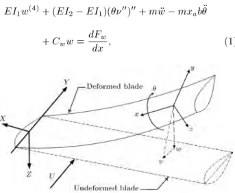
The considered wing model is a cantilevered wing model with bending displacements of w and and torsion of , which are shown in Figure 1. The ap deection is denoted by w, positive downward direction; lag deection is denoted by , positive stream-wise direction; and pitch angle, , is positive nose up. A sketch of the wing section is shown in Figure 2, where c is the chord, b is the semi-chord length, ahb is the distance from the wing section
mid-chord to the elastic axis, and xab is the distance from
the elastic axis to the center of mass. The length of the wing is L .
Hodges-Dowell equations of motion for a uniform elastic wing, ignoring the wing section warping, are as follows [18]:
EI1w(4)+ (EI2 EI1)(00)00+ m w mxab
+ Cww = dFdxw; (1)
Figure 2. Schematic gure of the wing section.
GJ00+ (EI
2 EI1)w0000+ mr12 mxabw
+ C_ = dMdxx; (2)
EI2(40)+(EI2 EI1)(w00)00+m+C_ =dFdx; (3)
where m; ra; EI1; EI2; GJ; Cw; C and C are mass
per unit length of the wing, radius of gyration about mass center, chord-wise and span-wise bending sti-ness, torsional stisti-ness, respectively. dFw=dx; dMx=dx,
and dF=dx are aerodynamic forces and moments.
2.2. Unsteady aerodynamics model
According to work presented in [2,3,7], aerodynamic forces and moments for unsteady aerodynamics models are as follows:
dFw= dL + 0dD; (4)
dMx= dMxf; (5)
dF = dD + 0dL; (6)
where 0; L(t); M(t), and D(t) are a constant angle
of attack, aerodynamic lift, moment and drag, respec-tively. Aerodynamic forces on the xed wing model in a ow, with free ow speed, U, and according to Figure 1, are as follows [19]:
L() = U2f(w00 a
hb00+ b0)
+ 2hb(0) = h0(0) +1
2 ah
b0(0)i()
+ 2
r
Z
0
( )[b0() + h00()1
2 ah
b0()]dg; (7)
M() =2U21
2+ ah nh
b(0) + h0(0)
+
1 2 ah
b0(0)i()
+
r
Z
0
( )hb0() + h00()
+
1 2 ah
d0()ido
+ U2a
hb(w00 ahb00)
1 2 ah
b2U20 b2U2
8 00: (8) In these terms, all derivatives signed by (0) are based on
dimensionless time, , as = Ut=b. Wagner's function () shows the ow is unsteady and is given by:
() = 1 1e 1t 2e 2t; (9)
where 1 = 0:165; "1 = 0:041; 1 = 0:355, and "2 =
0:32 [8]. By inserting Eq. (9) into Eqs. (7) and (8) and using the integrating by parts, lift force L() and moment M() will be as follows:
L()=U2fw00 a
hb+[1+(1 2ah)(0)]0+2(0)w0
+2b[(0) +(0:5 ah)0(0)]() +20(0)w()
+ 2b 11[1 (0:5 ah)1]w1+2b 22[1
(0:5 ah)2]w2 2 212w3 2 222w4
b(1 2ah)0()(0) 20()w(0)]g; (10)
M()=U2bna hw00 b
1 8+a2h
00+(1+2a
h)(0)w0
+ (1 + 2ah)(0)w+b(0:5 ah)[(1 + 2ah)(0)
1]0+b(1 + 2a
h)(0) + (0:5 ah)0(0)
+b(1 + 2ah) 11
h
1 (0:5 ah)1
i w1
(1 + 2ah) 121w2+b(1 + 2ah) 22
h 1 (0:5 ah)2
i
w2 (1 + 2ah) 222w4 (1
+2ah)0()w(0) b(0:5 2a2h)0()(0)
o ; (11)
which, in accordance with the denitions given by Lee et al [20], w1; w2 w3 and w4 variables are dened as
follows: w1=
Z
0
e 1( )()d; w
2=
Z
0
e 2( )()d;
w3=
Z
0
e 1( )w()d; w
4=
Z
0
e 2( )w()d:
(12) These variables have been dened because of existing integral terms of the aerodynamics model (unsteady part of the ow). The aerodynamics center of and the distance between the elastic axis and the wing mid-chord of xf are dened by:
e = xcf 14; xf = b2+ ahb: (13)
In addition, by ignoring drag force, we can write:
dD = 0: (14)
2.3. Discretizing aeroelastic equations
By substituting aerodynamic forces and moments, in accordance with Eqs. (7) and (8) in the structural equations of motion (Eqs. (1)-(3)), complete aeroelastic equations will be obtained. These equations can be discretized according to the assumed mode and Galerkin's method. In these methods, the w; and displacements are explained in terms of multiplying generalized coordinate and mode shapes, which satisfy geometric boundary conditions. Then, by substituting these displacements in equations of motion, multiplying each equation with an admissible mode function and integrating along the whole area of the wing, the equations of motion will be discretized. Hence the ap, lag and torsion displacements can be described as follows:
w(x; t) =XWi(t) i(x); (x; t) =
X
i(t)i(x);
(x; t) =XVi(t)ai(x);
w1=
X
w1j()j(x); w2=
X
w2j()j(x);
w3=
X
w3j() i(x); w4=
X
w4j() i(x); (15)
where: w1j=
Z
0
e 1( )
j()d; w2j
Z
0
e 2( )
j()d;
w3j=
Z
0
e 1( )
j()d; w4j=
Z
0
e2( )
j()d;
(16)
where Wi(t); i(t) and Vi(t) are generalized
coordi-nates, and i(x); i(x) and ai(x) are mode shapes that
satisfy geometric boundary conditions. Appropriate mode shapes for description of the displacements of w; v and are obtained from the beams and rod with equiv-alent boundary conditions to the wing model. This aeroelastic model has ap, lag and torsion motions. Flag and lag motions are transverse displacements. According to the Rayleigh-Ritz method, displacements can be written in terms of generalized coordinates and assumed mode functions. These mode functions must satisfy geometric boundary conditions. Accordingly, ap and lag displacements are written in terms of mode functions of the Euler-Bernoulli cantilever beam, and torsion displacement is expressed in terms of the xed-free mode function of the shaft or rod. These mode shapes are as follows:
For bending modes:
n=sin nLx sinh nLx+an
cos nLx cosh nLx
; (17) that:
n = 1:8751; 4:6941; 7:8547; 10:9955; 10:9955 + ;
an= (cos n cosh n)=(sin n= sinh n);
and, for torsional modes: n= sin
2n 1 2 x L : (18)
The following non-dimensional quantities are intro-duced:
= U1b t; = wb; = b;
ra=
r Ia
mb2; =
m
b2; U=
U b!a;
!= v u u u u u u t GJ IL2
1 R 0 00 1 2 dx 1 R 0 00 1 2 dx ! = v u u u u u u t EI1
ImL4
1 R 0 00 1 2 dx 1 R 0 1 2 dx ; ! = v u u u u u u t EI1
ImL4
1 R 0 00 a1 2 dx 1 R 0 a1 2 dx ;
! 1 =!!
a; ! 2 =!!
a; =
x
L; (19)
where and are dimensionless ap and lag deec-tions; !, ! and !a are the rst natural frequencies
of uncoupled ap, lag and pitching modes; U, ! i
and are dimensionless velocity, bending to torsion frequency ratios and mass ratio, respectively, and is dimensionless coordinate along the span of the wing. These dimensionless parameters are dened in order to select the necessary parameters, in accordance with the values given in [9], to validate the presented model, in accordance with the utter velocities in this reference.
By combining structural equations (Eqs. (1)-(3)) with aerodynamic equations (Eqs. (7)-(8)), expressing displacement variables according to Eq. (15), applying Galerkin's method and using dimensionless parameters given in Eq. (19), the original partial dierential equa-tions are converted to the following ordinary dierential equations:
2
4MM MM MM M M M
3 5 8 > > > > > > < > > > > > > : :: :: :: 9 > > > > > > = > > > > > > ; + 2
4CC CC CC C C C
3 5 8 < : 9 = ;+ 2
4KK KK KK K K K
3 5 8 < : 9 = ; + 2
4KK11 KK22 KK33 KK44 K1 K2 K3 K4
3 5 8 > > < > > : w1i w2i w3i w4i 9 > > = > > ;= 8 < : FN FN FN 9 = ; :(20)
Elements of each matrix and nonlinear terms in Eq. (20) are introduced in Appendix A.
According to the denition presented in Eq. (12), time derivatives of variables w1; w2; w3 and w4 are
dened as follows: d d 8 > > < > > : w1i w2i w3i w4i 9 > > = > > ;= 8 > > < > > : j j j j 9 > > = > > ; 2 6 6 4
1 0 0 0
0 2 0 0
0 0 1 0
0 0 0 2
3 7 7 5 8 > > < > > : w1i w2i w3i w4i 9 > > = > > ;(21): Aeroelastic equations can be obtained by combining Eqs. (20) and (21). These equations can be written briey as follows:
[Meq] fqg+[Ceq] f _qg+[Keq] fqg +[KLag]fwLagg=fFNg ;
dwLag
d
= fug [K] fwLagg ; (22)
where [Meq], [Ceq] and [Keq] are mass, damping and
stiness matrices and fFNg is a vector of structural
nonlinearity. [KLag] and [K] show the eect of
aerodynamics lag due to unsteadiness of ow. The vectors, fqg and fwLagg, are dened as fTTTgT and
fwLagg = fwT1iw2iT w3iT wT4igT, respectively.
Now, after presenting all aeroelastic equations, the validity and results obtained from these equations will be examined.
3. Aeroelastic results
In this section, the aeroelastic results of the presented wing model for dierent cases will be studied. For this purpose, at rst, wing structural and aerodynamics parameters will be selected. Wing sections and ight parameters are shown in Table 1. These parameters
Table 1. Wing model data.
Wing specication Values
Span (L) 0:6299 (m)
Chord (c) 0:1018 (m)
Dimensionless distance from wing section mid-chord to elastic axis (ah) 0:3
Dimensionless distance from elastic axis to center of mass (xa) 0:22
Flap structural modal damping (Cw) 0:02
Chord-wise structural modal damping (Cv) 0:025
Torsional structural modal damping (C) 0:031
Mass ratio () 48
Radius of gyration about elastic axis (r) 0:558
Natural frequencies in ap bending (!) 26 rads
Natural frequencies in chord-wise bending (!) 172:6 rads
Natural frequencies in torsion (!) 210 rads
Flight conditions
Density of air () 1:1 kg
m3
are selected compatible with parameters presented in [2,21]. These parameters are not selected accurately, according to parameters given in these references, since, in [2], the parameters are for a wing which represents stall phenomenon, and parameters given in [21] are for a simple wing model with plunge and pitch motions, with low speed and incompressible, irrotational aero-dynamic ow. Hence, combinations of the parameters given by these references are given in Table 1.
3.1. Eigenvalue solution of the linear
aeroelastic system at zero angle of attack At rst, the eignevalue solution of the linear aeroelastic system at zero angle of attack, which determines the stability of the linear part of the system, will be studied. For this purpose, considering the derivative of all variables in Eq. (22) equal to zero, the equilibrium point of the equation of motion will be determined. Then, by linearization of the nonlinear terms, an equiv-alent linear system around the equilibrium point will be obtained, and from this equivalent linear system, eigenvalue analysis is carried out.
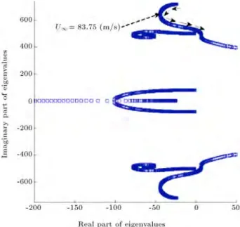
Changes of eigenvalues of the linear aeroelastic equation with free stream velocity have been shown in Figures 3-5. The damping and frequency of eigenvalues are given by the real and imaginary parts of eigenval-ues, , of the linear system. Dierent combinations of mode shapes are selected and the convergences of the eigenvalue solution are studied. For these gures, the number of the mode functions for ap, lag and torsion displacements are 4, 2 and 2. By increasing the number of mode shapes above these mentioned mode numbers, minor changes will occur in the predictions. A sample convergence of the solution, based on the number of the mode shapes, will be presented in the next section. As seen in Figure 3, by increasing the free stream
Figure 3. Real part (damping) of eigenvalues of the linearized aeroelastic system vs. free stream velocity, case 1.
Figure 4. Imaginary part (frequency) of eigenvalues of the linearized aeroelastic system vs. free stream velocity, case 1.
Figure 5. Imaginary part (frequeny) vs. real part (damping) of the eigenvalues of the linearized aeroelastic system, case 1.
velocity, one of the branches of the real part of the eigenvalues of the linear system will change its sign and become positive. In this case, the initially stable system becomes unstable. In utter velocity, a branch of eigenvalues has an intersection with the real axis. For this intersection, the real part of the corresponding eigenvalue is zero. When the utter velocity is UF =
102:271 m/s (Figure 4), by increasing free stream velocity, at rst, all branches move to the left side of the imaginary axis, which means more stability of the system, but, at a velocity of 83:75 m/s, two of these branches move towards the imaginary axis, which means that the system tends to be unstable.
After getting the branches to the imaginary boundaries and passing them, the linear system became unstable. Moreover, from Figure 5, it is clear that the two branches of eigenvalues approach each other gradually and near utter velocity, they have less distance from each other, which shows the bending-torsion utter mode. From Figure 4, the second mode of ap bending with the rst mode of torsion is the reason for the utter. In this type of utter, increasing the free stream velocity causes the bending frequency to increase and the torsion frequency to decrease. Once these frequen-cies become nearly equal, a utter of coupled bending-torsion occurs, whose eect is similar to the internal resonance phenomenon, and between these branches, an internal resonance occurs. Flutter is a linear dynamics phenomenon, in which the aerodynamics force dominates the dynamics inertial forces. In utter, unstable eigenvalues are in complex conjugate form, and the amplitude of vibration gradually increases with time. But, if there is nonlinearity in the system, the counter eects of unstable eigenvalues after utter velocity with nonlinear structural terms, lead to a non-linear vibration phenomenon, such as limit cycle. Limit cycle oscillation is a vibration with limited amplitude. Divergence is static instability, in which aerody-namic forces dominate structural force (wing stiness) without consideration of inertia forces. Explained mathematically, this is instability with pure positive real eigenvalue (eigenvalue without an oscillatory imag-inary part). For divergence of the wing, it is necessary for eigenvalues of a linearized system to go to the right half of the s-plane along the horizontal axis, without having an imaginary part. From Figure 5, some eigen-values of the considered linearized aeroelastic system lie on the negative horizontal axis. These real negative eigenvalues are due to the lag in aerodynamics force, i.e. dynamics of the aerodynamic forces through wLag
(Eq. (22)). Also, by varying velocity, two branches of eigenvalues, according to Figure 5, intersect and bifurcate, and one branch moves along the negative real axis, and another moves towards the positive real axis. For occurring divergent instability, it is necessary to increase the free stream velocity. For the case considered here, the required free stream velocity for divergent instability is beyond the applicability of the considered aerodynamics model. Hence, the free stream velocity is limited to the domain shown in these gures. As shown in Figure 5, the eigenvalues on real axes are on the left half plane. Similar forms of behavior are presented in [9,10].
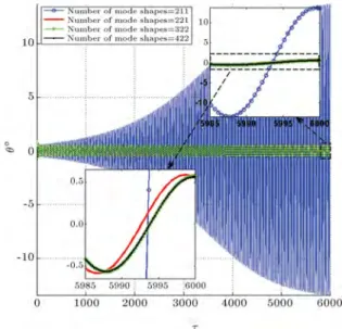
3.2. Solution convergence study
Here, the eect of dierent numbers of mode shape on the convergence of the solution will be studied. This convergence study is briey described in Figures 6-8. These gures show the displacement at the tip
Figure 6. Flap displacement of the nonlinear aeroelastic wing model at angle of attack 1 deg in U1= 102:271 m/s
for dierent combinations of mode shapes (tip of the wing).
Figure 7. Torsional displacement of the nonlinear aeroelastic wing model at angle of attack 1 deg in U1= 102:271 m/s for dierent combinations of mode
shapes (tip of the wing).
of the wing. As seen from these gures, there are minor changes of predictions based on the 3-2-2 and 4-2-2 number of mode shapes. Hence, selection of the 4, 2 and 2 mode shapes for ap, torsion and lag displacements are very justied.
3.3. Eect of the free stream velocity of limit cycle amplitudes
After examination of the linear stability of the aeroelas-tic model and selection of the correct number of mode shapes, the time response of the nonlinear aeroelastic
Figure 8. Lag displacement of the nonlinear aeroelastic wing model at angle of attack 1 deg in U1= 102:271 m/s
for dierent combinations of mode shapes (tip of the wing).
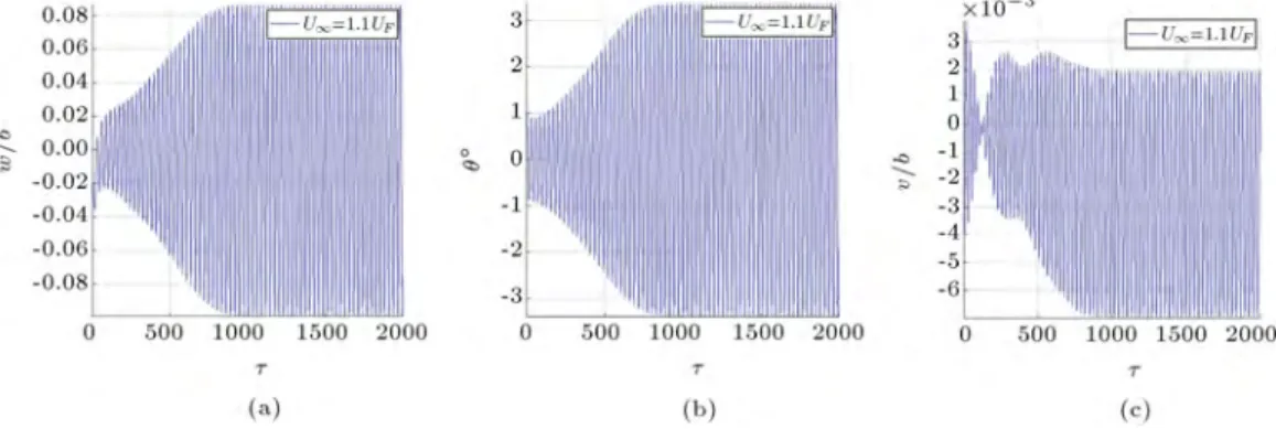
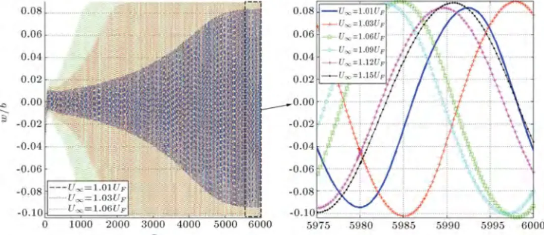
model in dierent velocities will be examined. The limit cycle oscillation amplitudes for two dierent velocities are shown in Figures 9 and 10.
As seen from Figure 9, in velocity less than the linear utter velocity, vibration amplitudes decreases with time and nally becomes damp. In this velocity,
all eigenvalues of the linear system have a negative real part, and the linear system is stable. Hence, the am-plitude of the oscillation gradually moves to zero. As seen from Figure 10, by increasing the free ow velocity above the utter boundary, limit cycle oscillations will occur. The reason is that in a velocity greater than linear utter, the linear system has complex conjugate positive real part eigenvalues, which tend to increase the amplitude of the vibrations. In the absence of the structurally nonlinear term, the amplitude of the oscillations tends to innity, while by increasing the amplitude of the oscillations, the nonlinear structural terms become suciently large and prevent further increase in the vibration amplitude. Hence, nally, the oscillation will settle down in a nonlinear absorber, which is the limit cycle, in this case.
The eects of the dierent free stream velocity in the time response of nonlinear aeroelastic model are shown in Figures 11-13. These displacements are shown for the tip of the wing. From Figure 13, by increasing velocity beyond linear utter velocity, the amplitude of the tip ap displacements increases at rst, and then, decreases. Similar forms of behavior are presented for torsion and lag displacements.
From Figure 12, the torsion displacement is sym-metric, but the ap and lag displacements of Figures 11 and 13 are not symmetric. The ap and lag displace-ments have a static deformation in the direction of the ow, and the whole of the wing will oscillate in
Figure 9. Wing tip (a), ap (b), torsion (c), and lag deections in U1= 0:9UF and angle of attack 1 deg.
Figure 11. Flap displacement of the nonlinear aeroelastic wing model in dierent free stream velocity at angle of attack 1 deg.
Figure 12. Torsion displacement of the nonlinear aeroelastic wing model in dierent free stream velocity at angle of attack 1 deg.
Figure 13. Lag displacement of the nonlinear aeroelastic wing model in dierent free stream velocity at angle of attack 1 deg.
the vicinity of this static displacement. According to these gures, in velocities greater than utter velocity, the aerodynamics force is divided into two sections. Some parts of the aerodynamics and structural forces counteract each other without inclusion of the iner-tial forces and produce a static displacement of the
wing. Remaining parts of the aerodynamics forces will counteract structural and inertial forces and produce oscillations around this static state. Hence, the limit cycle amplitudes decrease with increasing velocity.
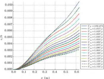
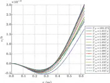
The maximum amplitudes of ap, torsion and lag displacements along the span of the wing are shown in
Figure 14. The ap displacement amplitude along the span of the wing for dierent velocities at angle of attack 1 deg.
Figure 15. The torsion displacement amplitude along the span of the wing for dierent velocities at angle of attack 1 deg.
Figures 14-16, respectively. According to Figure 14, for velocities greater than utter velocity, the ap displacement at the tip of the wing is nearly constant. By increasing free stream velocity up from 1:01 UF,
the torsion displacement decreases (Figure 15). For the lag displacement according to Figure 16, the maximum amplitude at the tip of the wing decreased with an increase in free stream velocity up to 1:15 UF. At
mid wing, the amplitude of the limit cycle oscillation decreased.
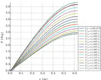
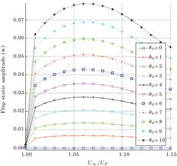
As shown in Figure 11, there is a certain static displacement in ap displacements. This static dis-placement has been shown in Figure 17 for the whole span of the wing. According to Figure 17, up to U1 = 1:05 UF by increasing velocity, static
dis-placement amplitude increases, and by increasing free stream velocity up from 1:06 UF, the static amplitude
Figure 16. The lag displacement amplitude along the span of the wing for dierent velocities at angle of attack 1 deg.
Figure 17. The ap static displacement along the span of the wing for dierent velocities at angle of attack 1 deg.
displacement decreases. There is a similar situation for torsion and lag static displacements, as shown in Figures 18 and 19.
Maximum limit cycle amplitudes along the wing span, at angle of attack, are shown in Figures 20-25.
According to Figures 21 and 22, in this angle of attack, by increasing free stream velocity, the lag and torsion amplitudes at the end of the wing, at rst, increase and then decrease, while there are not important changes for ap amplitudes. By comparing the results presented in Figures 14-19 with Figures 20-25, it is seen that by increasing the angle of attack from to, the lag displacements at the end of the wing are increased, while ap and torsion displacement has little change.
Also, by comparing Figures 17-19 and Figures 23-25, it is seen that the static displacements of the wing increase by increasing the angles of attack.
Figure 18. The torsion static displacement along the span of the wing for dierent velocities at angle of attack 1 deg.
Figure 19. The lag static displacement along the span of the wing for dierent velocities at angle of attack 1 deg.
Figure 20. The ap displacement amplitude along the span of the wing for dierent velocities at angle of attack 5 deg.
Figure 21. The torsion displacement amplitude along the span of the wing for dierent velocities at angle of attack 5 deg.
Figure 22. The lag displacement amplitude along the span of the wing for dierent velocities at angle of attack 5 deg.
Figure 23. The ap static displacement along the span of the wing for dierent velocities at angle of attack 5 deg.
Figure 24. The torsion static displacement along the span of the wing for dierent velocities at angle of attack 5 deg.
Figure 25. The lag static displacement along the span of the wing for dierent velocities at angle of attack 5 deg.
3.4. Eect of the attack angle on the limit cycle amplitude and frequency of nonlinear aeroelastic system
Now, the eect of the angle of the attack on limit cycle amplitudes will be examined. The ap, lag and torsion displacements at dierent velocities and dierent angles of attack are shown in Figures 26-28. According to these gures, by increasing the angle of attack from 0 to 10, lag amplitude increases gradually, while the changes of ap and torsion displacements are very small.
The variation of the ap static displacement with angle of attack is shown in Figure 29. According to this gure, by increasing angle of attack, the ap static amplitudes are increased by increasing free stream velocity. From these gures, it is clear that the amplitude of the oscillations in utter velocity is very sensitive to the changes in the angle of at-tack.
Figure 26. The ap displacement amplitude of the wing tip for dierent angle of attack.
Figure 27. The torsion displacement amplitude of the wing tip for dierent angle of attack.
The changes of the limit cycle oscillation fre-quency in dierent velocity and dierent angles of attack are shown in Figure 30. According to this gure, changes in angle of attack do not have any important eect on limit cycle frequency. The limit cycle frequencies decrease by increasing free stream velocity.
The wing tip cross section oscillations at the angle of attack of 1 deg are shown in Figure 31. According to Figure 31, in the extremum of motion, i.e., in the upper and lower part of the wing displacement, the main displacement is due to torsion, and sharp changes in the wing torsion occur. While between
Figure 28. The lag displacement amplitude of the wing tip for dierent angle of attack.
Figure 29. The ap static displacement amplitude of the wing tip for dierent angle of attack.
these extrema, motion mainly due to bending dis-placements and torsion disdis-placements gradually oc-curs.
Wing cross section oscillation at position has been shown in Figure 31. As seen from this gure, there is a node at the leading edge of the wing. The positions of this nodal line vary with free stream velocity and angle of attack.
4. Conclusion
In this study, the eect of the angle of attack on
Figure 30. The frequency of the limit cycle oscillations at dierent angle of attacks.
Figure 31. Wing cross section oscillations at position of 0:542 m at angle of attack 1 deg for velocity of
102:271 1:06 m/s.
the nonlinear behavior of high aspect ratio wings in unsteady low speed aerodynamic ow is carefully examined. The studied wing models have ap, lag and torsion displacements. According to this study, the limit cycle amplitudes are very sensitive to variations in angle of attack. With variation of the angle of attack, wings undergo a static displacement in each displacement. The frequency of limit cycle oscillations at dierent angles of attack and free stream veloc-ities is obtained. There are minor changes in the frequency of the limit cycle with variations in angle of attack.
Nomenclature
ah Dimensionless distance from wing
section mid-chord to elastic axis b Wing section semi-chord
Cv; Cw Structural chord-wise and vertical
bending damping coecents C Structural twist damping
c; c Wing chord and dimensionless chord, c=L
dD; dL Section drag and lift forces
dFv; dFw Chord-wise and vertical aerodynamic
forces
dMx Aerodynamic pitch moment about
elastic axis
dMxf aerodynamic pitch moment about
elastic axis
E Modulus of elasticity of wing e Section mass center distance from
elastic axis
G Shear modulus of elasticity h Plunge displacement
I1; I2 Vertical, chord-wise area moments of
inertia
J Torsional stiness constant L Wing span
m Mass per unit length of the wing r Radius of gyration about elastic axis
t Time
U; U Free-stream velocity and dimensionless
velocity
UF Flutter velocity
vi; Wi Generalized coordinates for ap lag
bending
Chord-wise or edgewise bending deection
w Vertical or apwise bending deection x Position coordinate along wing span xf Position of exural axis
x Dimensionless distance from elastic
axis to center of mass Pitch angle of wing section
i Generalized coordinates for torsion
0 Steady angle of attack at root section
Mass ratio
; Dimensionless ap and lag displacements
Air density
Dimensionless time
! Frequency of limit cycle oscillations
!; !; ! Natural frequencies in ap lag and
pitch !
1; !2 Frequency ratio
()0 d()=dx
(:) d()/dt
References
1. Hodges, D.H. and Dowell, E.H. \Nonlinear equations of motion for the elastic bending and torsion of twisted non-uniform rotor blades", NASA Technical note (1974).
2. Tang, D. and Dowell, E.H. \Experimental and theoret-ical study on aeroelastic response of high-aspect-ratio wings",AIAA Journal, 39(8), pp. 1430-1441 (2001).
3. Tang, D. and Dowell, E.H. \Experimental and theoret-ical study of gust response for high-aspect-ratio wing", AIAA Journal, 40(3), pp. 419-429 (2002).
4. Patil, M.J., Hodges, D.H. and Cesnik, C.E.S. \Limit-cycle oscillations in high-aspect-ratio wings", Journal of Fluids and Structures, 15(1), pp. 107-132 (2001).
5. Malatkar, P. \Nonlinear vibrations of cantilever beams and plates", PhD Dissertation, Virginia Polytechnic Institute and State University (2003).
6. Nichkawde, C. \Nonlinear aeroelastic analysis of high aspect ratio wings using the method of numerical con-tinuation", Msc Dissertation, Texas, A& M University (2006).
7. Tang, D.M., Henry, J.K. and Dowell, E.H. \Eects of steady angle of attack on nonlinear gust response of a delta wing model", Journal of Fluids and Structures, 16(8), pp. 1093-1110 (2002).
8. Gordnier, R.E. and Visbal, M.R. \Computation of the aeroelastic response of a exible delta wing at high angles of attack", Journal of Fluids and Structures, 19(6), pp. 785-800 (2004).
9. Tang, D.M. and Dowell, E.H. \Eects of angle of attack on nonlinear utter of a delta wing", AIAA Journal, 39, pp. 15-21 (2001).
10. Soltani, M.R., Ghorbanian, K. and Masdari, M. \Investigation of the pressure distribution and tran-sition point over a swept wing", Scientia Iran-ica, Transactions B: Mechanical Engineering (2011), doi:10.1016/j.scient.2011.10.001.
11. Ghadimi, M., Dardel, M., Pashaei, M.H. and Barze-gari, M.M. \Eects of geometric imperfections on the aeroelastic behavior of functionally graded wings in supersonic ow", Aerospace Science and Technology, 23, pp. 492-504 (2012).
12. Davari, A.R., Soltani, M.R., Askari, F. and Pajuhande, H.R. \Eects of wing geometry on wing-body-tail interference in subsonic ow", Scientia Iranica, Trans-actions B: Mechanical Engineering, 18, pp. 407-415 (2011).
13. Dardel, M. and Bakhtiari-nejad, F. \Limit cycle os-cillation control of wing with static output feedback control method", Aerospace Science and Technology, 24, pp. 147-160 (2013).
14. Jian, Z. and Jinwu, X. \Nonlinear aeroelastic response of high-aspect-ratio exible wings", Chinese Journal of Aeronautics, 22, pp. 355-363 (2009).
15. Qiang, W.Z., Hong, Y., Guang, L.D. and Chao, Y. \Aeroelastic analysis and optimization of high aspect ratio composite forward swept wings, Chinese Journal of Aeronautics, 18(4), pp. 317-325 (2005).
16. Gordnier, R.E., Chimakurthi, S.K., Cesnik, C.E.S. and Attar, P.J. \High-delity aeroelastic computations of a apping wing with span-wise exibility", Journal of Fluids and Structures, 40, pp. 86-104 (2013).
17. Xie, C., Wang, L., Yang, C. and Liu, Y. \Static aeroelastic analysis of very exible wings based on non-planar vortex lattice method", Chinese Journal of Aeronautics, 26(3), pp. 514-521 (2013).
18. Tang, D.M. and Dowell, E.H. \Eects of geometric structural nonlinearity on utter and limit cycle oscil-lations of high-aspect-ratio wings", Journal of Fluids and Structures, 19(3), pp. 291-306 (2004).
19. Fung, Y.C., An Introduction to the Theory of Aeroe-lasticity, John Wiley and Sons, Inc. (1995).
20. Lee, B.H.K., Liu, L. and Chung K.W. \Airfoil motion in subsonic ow with strong cubic nonlinear restoring forces", Journal of Sound and Vibration, 281, pp. 699-717 (2005).
21. Ghadiri, B. and Razi, M. \Limit cycle oscillations of rectangular cantilever wings containing cubic nonlin-earity in an incompressible ow", Journal of Fluids and Structures, 23(4), pp. 665-680 (2007).
Appendix A.
Aeroelastic matrices coecients: Mij =
1 + 1
Z1
0
i jd;
Mij =
xa ah
Z1
0
ijd;
Mij = 0; Mij = 0;
Mij= xa r2 a % ah r2 a Z1 0
i jd;
Mij =
1 +r12
a
a2
h+18
Z1
0
ijd;
Mij = 0; Mij = 0
1
Z
0
ai jd;
Mij =0ah
1
Z
0
aijd;
Mij =
1
Z
0
aiajdx;
Cij =
Cw
m!aU +
2(0)
Z1
0
i jd;
Cij = 1 + (1 2a h)(0)
1
Z
0
ijd;
Cij = 0; Cij = (2ah+ 1)(0)r2
a
1
Z
0
i jd;
Cij = 0 @ C
I!aU
(0:5 ah)
h
(1 + 2ah)(0) 1
i r2 a 1 A 1 Z 0
ijd;
Cij = 0; Cij = 02(0) 1
Z
0
aj jd;
Cij = 1 + (1 2a h)(0)
1
Z
0
aijd;
Cij
= m!C aU
1
Z
0
aiajd;
Kij=
! U
2R1
0 2 1dx 1 R 0 00 1 2 d 1 Z 0 00 k 00
id+2(0) 1
Z
0
k id;
Kki
= 2((0) + (0:5 ah) 0(0))
1
Z
0
kjd;
Kki
= 0; Kki= (2ah+ 1) 0(0) r2 a 1 Z 0
Kkj = N X j=1 j 2 6 6 6 4 1 U2 1 R 0 2 1d 1 R 0( 0 1)2d
1
Z
0
0 kjd
(2ah+1)[(0)+(0:5 ah)0(0)]
r2 a
1
Z
0
kjd
3 5 ;
Kkj= 0; Kkj= 02 0(0)
1
Z
0
ak id;
Kki
= 02((0) + (0:5 ah) 0(0))
1
Z
0
akjd;
Kij = ! 2 2 U2 1 R 0 a 2 1dx 1 R 0 a 2 1 dx 1 Z 0 a 1ajd;
Kki
1=2( 11[1 (0:5 a h)1]) 1
Z
0
kid;
Kki
2=2( 22[1 (0:5 a h)2]) 1
Z
0
kid;
Kki
3= 2 1 2 1 1 Z 0
k id; K4ki= 2 2 2 2 1 Z 0
k id;
K1kj= (2ah+ 1) 11r[1 (0:5 a2 h)1]
a
1
Z
0
kjd;
Kki
3=(2ah+ 1) 1 2 2 r2 a 1 Z 0
k id;
Kki
2= (2ah+ 1) 21[1 (0:5 ar2 h)2] a
1
Z
0
kjd;
Kki
4= (2ah+ 1) 2 2 2 r2 a 1 Z 0
k id;
Kki
1= 02( 11[1 (0:5 a h)1]) 1
Z
0
akid;
Kki
2= 02 22[1 (0:5 a h)2] 1
Z
0
akid;
Kki
3=02 1 2 1 1 Z 0
ak id; K4ki= 02 2 2 2] 1 Z 0
ak id;
FN=
EI2
EI1 1
!2 1 U2 1 R 0 2 1d 1 R 0 002 1 d N X j=1 N X k=1
jk
Z1
0 0 ia
00
j0kd+ 1 Z 0 0 ia 000
j kd
+(1 2ah)0() X j(0) 1 Z 0
kjd+2 0() X i(0) 1 Z 0
k id;
FN=
EI2
EI1 1
!2
1
r2 aU2
1 R 0 2 1dx 1 R 0 002 1 dx N X j=1 N X k=1
jk 1 Z 0 0 i 00 ja 00 kd
(0:5 2a2 h)0()
r2 a X j(0) 1 Z 0
kjd
(2ah+ 1)0()
r2 1 X i(0) 1 Z 0
k id;
FN=
1 EIEI1
2 !2 2 U2 1 R 0 a 2 1dx 1 R 0 a 2 1 dx N X j=1 N X k=1
jk
Z1
0
a0 1
00
j0kd + 1 Z 0 a0 1 000
j kd
+ 0(1 2ah) 0() X j(0) 1 Z 0
akjd
+ 02 0() X i(0) 1 Z 0
Biographies
Morteza Dardel received a PhD degree in Solid Mechanics from Amirkabir University (Polytechnic of Tehran), Iran, in 2009, and is currently Assistant Professor in the faculty of Mechanical Engineering at Babol Noushirvani University of Technology, Iran.His research interests include aeroelasticity, nonlinear dy-namics, vibration and control of continuous systems and smart structures.
Keivan Eskandary obtained BS and MS degrees in Engineering Mechanics from Mazandaran University, Iran, and is currently pursuing his academic career at Chamran University, Iran. His research interests include mechanical nonlinear vibrations and dynamics, thermo-elastic and viscoelastic laminate.
Mohammad Hadi Pashaei received a PhD degree from Surrey University, UK, in Space Structures, in 2004, and is currently Assistant Professor in the Fac-ulty of Mechanical Engineering at Babol Noushirvani University of Technology, Iran. His research interests include structural dynamics, damping in structures and vibrational systems analysis.
Seyed Amir Hossein Kiaeian Moosavi received a MS degree from Babol University of Technology, Iran, in 2010, and is currently pursuing a PhD de-gree in Industrial and Information Engineering at the Department of Electrical, Mechanical and Manage-rial Engineering of the University of Udine. His research interests include dynamic modeling and vi-bration control of mechanisms with deformable mem-bers.