DOE FUNDAMENTALS HANDBOOK
NUCLEAR PHYSICS
AND REACTOR THEORY
Volume 2 of 2
U.S. Department of Energy
FSC-6910
Washington, D.C. 20585
Available to DOE and DOE contractors from the Office of Scientific and Technical Information, P.O. Box 62, Oak Ridge, TN 37831.
Available to the public from the National Technical Information Service, U.S. Department of Commerce, 5285 Port Royal., Springfield, VA 22161.
ABSTRACT
The Nuclear Physics and Reactor Theory Handbook was developed to assist nuclear
facility operating contractors in providing operators, maintenance personnel, and the technical staff with the necessary fundamentals training to ensure a basic understanding of nuclear physics and reactor theory. The handbook includes information on atomic and nuclear physics; neutron characteristics; reactor theory and nuclear parameters; and the theory of reactor operation. This information will provide personnel with a foundation for understanding the scientific principles that are associated with various DOE nuclear facility operations and maintenance.
K ey W ords: Training Material, Atomic Physics, The Chart of the Nuclides, Radioactivity, Radioactive Decay, Neutron Interaction, Fission, Reactor Theory, Neutron Characteristics, Neutron Life Cycle, Reactor Kinetics
F OREWOR D
The Department of Energy (DOE) Fundamentals Handbooks consist of ten academic
subjects, which include Mathematics; Classical Physics; Thermodynamics, Heat Transfer, and Fluid Flow; Instrumentation and Control; Electrical Science; Material Science; Mechanical Science; Chemistry; Engineering Symbology, Prints, and Drawings; and Nuclear Physics and Reactor Theory. The handbooks are provided as an aid to DOE nuclear facility contractors.
These handbooks were first published as Reactor Operator Fundamentals Manuals in 1985 for use by DOE category A reactors. The subject areas, subject matter content, and level of detail of the Reactor Operator Fundamentals Manuals were determined from several sources. DOE Category A reactor training managers determined which materials should be included, and served as a primary reference in the initial development phase. Training guidelines from the commercial nuclear power industry, results of job and task analyses, and independent input from contractors and operations-oriented personnel were all considered and included to some degree in developing the text material and learning objectives.
The DOE Fundamentals Handbooks represent the needs of various DOE nuclear facilities'
fundamental training requirements. To increase their applicability to nonreactor nuclear facilities, the Reactor Operator Fundamentals Manual learning objectives were distributed to the Nuclear Facility Training Coordination Program Steering Committee for review and comment. To update their reactor-specific content, DOE Category A reactor training managers also reviewed and commented on the content. On the basis of feedback from these sources, information that applied to two or more DOE nuclear facilities was considered generic and was included. The final draft of each of the handbooks was then reviewed by these two groups. This approach has resulted in revised modular handbooks that contain sufficient detail such that each facility may adjust the content to fit their specific needs.
Each handbook contains an abstract, a foreword, an overview, learning objectives, and text material, and is divided into modules so that content and order may be modified by individual DOE contractors to suit their specific training needs. Each handbook is supported by a separate examination bank with an answer key.
The DOE Fundamentals Handbooks have been prepared for the Assistant Secretary for
Nuclear Energy, Office of Nuclear Safety Policy and Standards, by the DOE Training Coordination Program. This program is managed by EG&G Idaho, Inc.
OVERVIEW
The Department of Energy Fundamentals Handbook entitled Nuclear Physics and Reactor
Theory was prepared as an information resource for personnel who are responsible for the
operation of the Department's nuclear facilities. Almost all processes that take place in a nuclear facility involves the transfer of some type of energy. A basic understanding of nuclear physics and reactor theory is necessary for DOE nuclear facility operators, maintenance personnel, and the technical staff to safely operate and maintain the facility and facility support systems. The information in this handbook is presented to provide a foundation for applying engineering concepts to the job. This knowledge will help personnel understand the impact that their actions may have on the safe and reliable operation of facility components and systems.
The Nuclear Physics and Reactor Theory handbook consists of four modules that are
contained in two volumes. The following is a brief description of the information presented in each module of the handbook.
Volume 1 of 2
Module 1 - Atomic and Nuclear Physics
Introduces concepts of atomic physics including the atomic nature of matter, the chart of the nuclides, radioactivity and radioactive decay, neutron interactions and fission, and the interaction of radiation with matter.
Module 2 - Reactor Theory (Nuclear Parameters)
Provides information on reactor theory and neutron characteristics. Includes topics such as neutron sources, neutron flux, neutron cross sections, reaction rates, neutron moderation, and prompt and delayed neutrons.
OVERVIEW (Cont.)
Volume 2 of 2
Module 3 - Reactor Theory (Nuclear Parameters)
Explains the nuclear parameters associated with reactor theory. Topics include the neutron life cycle, reactivity and reactivity coefficients, neutron poisons, and control rods.
Module 4 - Reactor Theory (Reactor Operations)
Introduces the reactor operations aspect of reactor theory. Topics include subcritical multiplication, reactor kinetics, and reactor operation.
The information contained in this handbook is not all-encompassing. An attempt to present the entire subject of nuclear physics and reactor theory would be impractical. However,
the Nuclear Physics and Reactor Theory handbook presents enough information to provide the
reader with the fundamental knowledge necessary to understand the advanced theoretical concepts presented in other subject areas, and to understand basic system and equipment operation.
Fundamentals Handbook
NUCLEAR PH YSICS
AND REACTOR TH EO RY
M odule 3
TABLE OF C ONTENTS
LIST OF FIGURES . . . iii
LIST OF TABLES . . . iv
REFERENCES . . . v
OBJECTIVES . . . vi
NEUTRON LIFE CYCLE . . . 1
Infinite Multiplication Factor, k∞ . . . 2
Four Factor Formula . . . 2
Fast Fission Factor, ( ) . . . 3
Resonance Escape Probability, (p) . . . 3
Thermal Utilization Factor, (f) . . . 4
Reproduction Factor, (η) . . . 6
Effective Multiplication Factor . . . 8
Fast Non-Leakage Probability ( f) . . . 9
Thermal Non-Leakage Probability ( t) . . . 9
Six Factor Formula . . . 10
Neutron Life Cycle of a Fast Reactor . . . 14
Summary . . . 14
REACTIVITY . . . 17
Application of the Effective Multiplication Factor . . . 17
Reactivity . . . 18
Units of Reactivity . . . 19
Reactivity Coefficients and Reactivity Defects . . . 21
Summary . . . 22
REACTIVITY COEFFICIENTS . . . 23
Moderator Effects . . . 24
Moderator Temperature Coefficient . . . 26
Fuel Temperature Coefficient . . . 26
Pressure Coefficient . . . 27
Void Coefficient . . . 27
TABLE OF C ONTENTS (Cont.)
NEUTRON POISONS . . . 30
Fixed Burnable Poisons . . . 30
Soluble Poisons . . . 31
Non-Burnable Poisons . . . 32
Summary . . . 33
XENON . . . 34
Fission Product Poisons . . . 34
Production and Removal of Xenon-135 . . . 35
Xenon-135 Response to Reactor Shutdown . . . 38
Xenon-135 Oscillations . . . 39
Xenon-135 Response to Reactor Power Changes . . . 40
Summary . . . 41
SAMARIUM AND OTHER FISSION PRODUCT POISONS . . . 43
Production and Removal of Samarium-149 . . . 43
Samarium-149 Response to Reactor Shutdown . . . 45
Other Neutron Poisons . . . 46
Summary . . . 47
CONTROL RODS . . . 48
Selection of Control Rod Materials . . . 48
Types of Control Rods . . . 49
Control Rod Effectiveness . . . 50
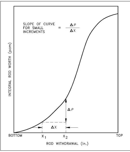
Integral and Differential Control Rod Worth . . . 51
Rod Control Mechanisms . . . 57
LIST OF FIGURES
Figure 1 Neutron Life Cycle with keff = 1 . . . 11
Figure 2 Effects of Over and Under Moderation on keff . . . 25
Figure 3 Effect of Fuel Temperature on Resonance Absorption Peaks . . . 27
Figure 4 Equilibrium Iodine-135 and Xenon-135 Concentrations Versus Neutron Flux . . 37
Figure 5 Xenon-135 Reactivity After Reactor Shutdown . . . 38
Figure 6 Xenon-135 Variations During Power Changes . . . 40
Figure 7 Behavior of Samarium-149 in a Typical Light Water Reactor . . . 46
Figure 8 Effect of Control Rod on Radial Flux Distribution . . . 50
Figure 9 Integral Control Rod Worth . . . 51
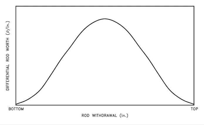
Figure 10 Differential Control Rod Worth . . . 52
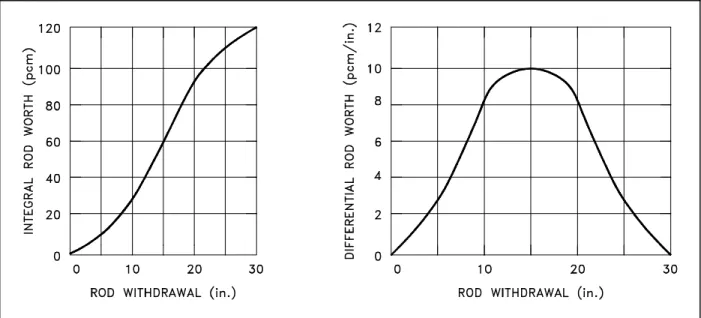
Figure 11 Rod Worth Curves for Example Problems . . . 53
LIST OF TABLES
REFERENCES
Foster, Arthur R. and Wright, Robert L. Jr., Basic Nuclear Engineering, 3rd Edition, Allyn and Bacon, Inc., 1977.
Jacobs, A.M., Kline, D.E., and Remick, F.J., Basic Principles of Nuclear Science and Reactors, Van Nostrand Company, Inc., 1960.
Kaplan, Irving, Nuclear Physics, 2nd Edition, Addison-Wesley Company, 1962.
Knief, Ronald Allen, Nuclear Energy Technology: Theory and Practice of Commercial Nuclear Power, McGraw-Hill, 1981.
Lamarsh, John R., Introduction to Nuclear Engineering, Addison-Wesley Company, 1977. Lamarsh, John R., Introduction to Nuclear Reactor Theory, Addison-Wesley Company, 1972.
General Electric Company, Nuclides and Isotopes: Chart of the Nuclides, 14th Edition, General Electric Company, 1989.
Academic Program for Nuclear Power Plant Personnel, Volume III, Columbia, MD, General Physics Corporation, Library of Congress Card #A 326517, 1982.
Glasstone, Samuel, Sourcebook on Atomic Energy, Robert F. Krieger Publishing Company, Inc., 1979.
Glasstone, Samuel and Sesonske, Alexander, Nuclear Reactor Engineering, 3rd Edition, Van Nostrand Reinhold Company, 1981.
TERMINAL OBJECTIVE
1.0 Using appropriate references, DESCRIBE the neutron life cycle discussed in this module.
ENABLING OBJECTIVE S
1.1 DEFINE the following terms:
a. Infinite multiplication factor, k∞
b. Effective multiplication factor, keff
c. Subcritical d. Critical e. Supercritical
1.2 DEFINE each term in the six factor formula using the ratio of the number of neutrons present at different points in the neutron life cycle.
1.3 Given the macroscopic cross sections for various materials, CALCULATE the thermal utilization factor.
1.4 Given microscopic cross sections for absorption and fission, atom density, and ν, CALCULATE the reproduction factor.
1.5 Given the numbers of neutrons present at the start of a generation and values for each factor in the six factor formula, CALCULATE the number of neutrons that will be present at any point in the life cycle.
1.6 LIST physical changes in the reactor core that will have an effect on the thermal utilization factor, reproduction factor, or resonance escape probability.
1.7 EXPLAIN the effect that temperature changes will have on the following factors: a. Thermal utilization factor
b. Resonance escape probability c. Fast non-leakage probability d. Thermal non-leakage probability
ENABLING OBJECTIVES (Cont.)
1.9 DEFINE the term reactivity.
1.10 CONVERT between reactivity and the associated value of keff. 1.11 CONVERT measures of reactivity between the following units:
a. ∆k/k c. 10-4 ∆k/k
b. %∆k/k d. Percent millirho (pcm)
TERMINAL OBJECTIVE
2.0 From memory, EXPLAIN how reactivity varies with the thermodynamic properties of the moderator and the fuel.
ENABLING OBJECTIVE S
2.1 EXPLAIN the conditions of over moderation and under moderation.
2.2 EXPLAIN why many reactors are designed to be operated in an under moderated condition.
2.3 STATE the effect that a change in moderator temperature will have on the moderator to fuel ratio.
2.4 DEFINE the temperature coefficient of reactivity.
2.5 EXPLAIN why a negative temperature coefficient of reactivity is desirable.
2.6 EXPLAIN why the fuel temperature coefficient is more effective than the moderator temperature coefficient in terminating a rapid power rise.
2.7 EXPLAIN the concept of Doppler broadening of resonance absorption peaks.
2.8 LIST two nuclides that are present in some types of reactor fuel assemblies that have significant resonance absorption peaks.
2.9 DEFINE the pressure coefficient of reactivity.
2.10 EXPLAIN why the pressure coefficient of reactivity is usually negligible in a reactor cooled and moderated by a subcooled liquid.
2.11 DEFINE the void coefficient of reactivity.
2.12 IDENTIFY the moderator conditions under which the void coefficient of reactivity becomes significant.
TERMINAL OBJECTIVE
3.0 Without references, DESCRIBE the use of neutron poisons.
ENABLING OBJECTIVE S
3.1 DEFINE the following terms: a. Burnable poison b. Non-burnable poison c. Chemical shim
3.2 EXPLAIN the use of burnable neutron poisons in a reactor core.
3.3 LIST the advantages and disadvantages of chemical shim over fixed burnable poisons. 3.4 STATE two reasons why fixed non-burnable neutron poisons are used in reactor cores. 3.5 STATE an example of a material used as a fixed non-burnable neutron poison.
TERMINAL OBJECTIVE
4.0 Without references, DESCRIBE the effects of fission product poisons on a reactor.
ENABLING OBJECTIVE S
4.1 LIST two methods of production and two methods of removal for xenon-135 during reactor operation.
4.2 STATE the equation for equilibrium xenon-135 concentration.
4.3 DESCRIBE how equilibrium xenon-135 concentration varies with reactor power level. 4.4 DESCRIBE the causes and effects of a xenon oscillation.
4.5 DESCRIBE how xenon-135 concentration changes following a reactor shutdown from steady-state conditions.
4.6 EXPLAIN the effect that pre-shutdown power levels have on the xenon-135 concentration after shutdown.
4.7 STATE the approximate time following a reactor shutdown at which the reactor can be considered "xenon free."
4.8 EXPLAIN what is meant by the following terms: a. Xenon precluded startup
b. Xenon dead time
4.9 DESCRIBE how xenon-135 concentration changes following an increase or a decrease in the power level of a reactor.
4.10 DESCRIBE how samarium-149 is produced and removed from the reactor core during reactor operation.
ENABLING OBJECTIVES (Cont.)
4.13 DESCRIBE how samarium-149 concentration changes following a reactor shutdown from steady-state conditions.
4.14 DESCRIBE how samarium-149 concentration changes following a reactor startup. 4.15 STATE the conditions under which helium-3 will have a significant effect on the
TERMINAL OBJECTIVE
5.0 Without references, DESCRIBE how control rods affect the reactor core.
ENABLING OBJECTIVE S
5.1 DESCRIBE the difference between a "grey" neutron absorbing material and a "black" neutron absorbing material.
5.2 EXPLAIN why a "grey" neutron absorbing material may be preferable to a "black" neutron absorbing material for use in control rods.
5.3 EXPLAIN why resonance absorbers are sometimes preferred over thermal absorbers as a control rod material.
5.4 DEFINE the following terms: a. Integral control rod worth b. Differential control rod worth
5.5 DESCRIBE the shape of a typical differential control rod worth curve and explain the reason for the shape.
5.6 DESCRIBE the shape of a typical integral control rod worth curve and explain the reason for the shape.
5.7 Given an integral or differential control rod worth curve, CALCULATE the reactivity change due to a control rod movement between two positions.
5.8 Given differential control rod worth data, PLOT differential and integral control rod worth curves.
NEUTRON LIFE C YCLE
Some number of the fast neutrons produced by fission in one generation will eventually cause fission in the next generation. The series of steps that fission neutrons go through as they slow to thermal energies and are absorbed in the reactor is referred to as the neutron life cycle. The neutron life cycle is markedly different between fast reactors and thermal reactors. This chapter presents the neutron life cycle for thermal reactors.
EO 1.1 DEFINE the following term s:
a. Infinite m ultiplication factor, k∞∞ d. Critical
b. Effective m ultiplication factor, keff e. Supercritical
c. Subcritical
EO 1.2 DEFINE each term in the six factor form ula using the ratio of the num ber of neutrons present at different points in the neutron life cycle.
EO 1.3 Given the m acroscopic cross sections for various m aterials, CALCULATE the therm al utilization factor.
EO 1.4 Given m icroscopic cross sections for absorption and fission, atom density, and νν, CALCULATE the reproduction factor. EO 1.5 Given the numbers of neutrons present at the start of a generation
and values for each factor in the six factor formula, CALCULATE the num ber of neutrons that will be present at any point in the life cycle.
EO 1.6 LIST physical changes in the reactor core that will have an effect on the therm al utilization factor, reproduction factor, or resonance escape probability.
EO 1.7 EXPLAIN the effect that tem perature changes will have on the following factors:
a. Therm al utilization factor b. Resonance escape probability c. Fast non-leakage probability d. Therm al non-leakage probability
Infinite M ultiplication Factor, k∞∞
Not all of the neutrons produced by fission will have the opportunity to cause new fissions because some neutrons will be absorbed by non-fissionable material. Some will be absorbed parasitically in fissionable material and will not cause fission, and others will leak out of the reactor. For the maintenance of a self-sustaining chain reaction, however, it is not necessary that every neutron produced in fission initiate another fission. The minimum condition is for each nucleus undergoing fission to produce, on the average, at least one neutron that causes fission of another nucleus. This condition is conveniently expressed in terms of a multiplication factor.
The number of neutrons absorbed or leaking out of the reactor will determine the value of this multiplication factor, and will also determine whether a new generation of neutrons is larger, smaller, or the same size as the preceding generation. Any reactor of a finite size will have neutrons leak out of it. Generally, the larger the reactor, the lower the fraction of neutron leakage. For simplicity, we will first consider a reactor that is infinitely large, and therefore has no neutron leakage. A measure of the increase or decrease in neutron flux in an infinite reactor is the infinite multiplication factor, k∞. The infinite multiplication factor is the ratio of the neutrons produced by fission in one generation to the number of neutrons lost through absorption in the preceding generation. This can be expressed mathematically as shown below.
k∞ neutron production from fission in one generation neutron absorption in the preceding generation
Four Factor Form ula
A group of fast neutrons produced by fission can enter into several reactions. Some of these reactions reduce the size of the neutron group while other reactions allow the group to increase in size or produce a second generation. There are four factors that are completely independent of the size and shape of the reactor that give the inherent multiplication ability of the fuel and moderator materials without regard to leakage. This four factor formula accurately represents the infinite multiplication factor as shown in the equation below.
k∞ = p f η where:
= fast fission factor
p = resonance escape probability f = thermal utilization factor
Fast Fission Factor, (
)
The first process that the neutrons of one generation may undergo is fast fission. Fast fission is fission caused by neutrons that are in the fast energy range. Fast fission results in the net increase in the fast neutron population of the reactor core. The cross section for fast fission in uranium-235 or uranium-238 is small; therefore, only a small number of fast neutrons cause fission. The fast neutron population in one generation is therefore increased by a factor called the fast fission factor. The fast fission factor ( ) is defined as the ratio of the net number of fast neutrons produced by all fissions to the number of fast neutrons produced by thermal fissions. The mathematical expression of this ratio is shown below.
number of fast neutrons produced by all fissions number of fast neutrons produced by thermal fissions
In order for a neutron to be absorbed by a fuel nucleus as a fast neutron, it must pass close enough to a fuel nucleus while it is a fast neutron. The value of will be affected by the arrangement and concentrations of the fuel and the moderator. The value of is essentially 1.00 for a homogenous reactor where the fuel atoms are surrounded by moderator atoms. However, in a heterogeneous reactor, all the fuel atoms are packed closely together in elements such as pins, rods, or pellets. Neutrons emitted from the fission of one fuel atom have a very good chance of passing near another fuel atom before slowing down significantly. The arrangement of the core elements results in a value of about 1.03 for in most heterogeneous reactors. The value of is not significantly affected by variables such as temperature, pressure, enrichment, or neutron poison concentrations. Poisons are non-fuel materials that easily absorb neutrons and will be discussed in more detail later.
Resonance Escape Probability, (p)
After increasing in number as a result of some fast fissions, the neutrons continue to diffuse through the reactor. As the neutrons move they collide with nuclei of fuel and non-fuel material and moderator in the reactor losing part of their energy in each collision and slowing down. While they are slowing down through the resonance region of uranium-238, which extends from about 6 eV to 200 eV, there is a chance that some neutrons will be captured. The probability that a neutron will not be absorbed by a resonance peak is called the resonance escape probability. The resonance escape probability (p) is defined as the ratio of the number of neutrons that reach thermal energies to the number of fast neutrons that start to slow down. This ratio is shown below.
p number of neutrons that reach thermal energy number of fast neutrons that start to slow down
The value of the resonance escape probability is determined largely by the fuel-moderator arrangement and the amount of enrichment of uranium-235 (if any is used). To undergo resonance absorption, a neutron must pass close enough to a uranium-238 nucleus to be absorbed while slowing down. In a homogeneous reactor the neutron does its slowing down in the region of the fuel nuclei, and this condition is easily met. This means that a neutron has a high probability of being absorbed by uranium-238 while slowing down; therefore, its escape probability is lower. In a heterogeneous reactor, however, the neutron slows down in the moderator where there are no atoms of uranium-238 present. Therefore, it has a low probability of undergoing resonance absorption, and its escape probability is higher.
The value of the resonance escape probability is not significantly affected by pressure or poison concentration. In water moderated, low uranium-235 enrichment reactors, raising the temperature of the fuel will raise the resonance absorption in uranium-238 due to the doppler effect (an apparent broadening of the normally narrow resonance peaks due to thermal motion of nuclei). The increase in resonance absorption lowers the resonance escape probability, and the fuel temperature coefficient for resonance escape is negative (explained in detail later). The temperature coefficient of resonance escape probability for the moderator temperature is also negative. As water temperature increases, water density decreases. The decrease in water density allows more resonance energy neutrons to enter the fuel and be absorbed. The value of the resonance escape probability is always slightly less than one (normally 0.95 to 0.99).
The product of the fast fission factor and the resonance escape probability ( p) is the ratio of the number of fast neutrons that survive slowing down (thermalization) compared to the number of fast neutrons originally starting the generation.
Therm al Utilization Factor, (f)
Once thermalized, the neutrons continue to diffuse throughout the reactor and are subject to absorption by other materials in the reactor as well as the fuel. The thermal utilization factor describes how effectively thermal neutrons are absorbed by the fuel, or how well they are utilized within the reactor. The thermal utilization factor (f) is defined as the ratio of the number of thermal neutrons absorbed in the fuel to the number of thermal neutrons absorbed in any reactor material. This ratio is shown below.
f number of thermal neutrons absorbed in the fuel number of thermal neutrons absorbed in all reactor materials
The thermal utilization factor will always be less than one because some of the thermal neutrons absorbed within the reactor will be absorbed by atoms of non-fuel materials.
An equation can be developed for the thermal utilization factor in terms of reaction rates as follows.
f rate of absorption of thermal neutrons by the fuel rate of absorption of thermal neutrons by all reactor materials
f Σ U
a φ U VU
ΣU a φ
U VU Σm a φ
m Vm Σp a φ
p Vp
The superscripts U, m, and p refer to uranium, moderator, and poison, respectively. In a heterogeneous reactor, the flux will be different in the fuel region than in the moderator region due to the high absorption rate by the fuel. Also, the volumes of fuel, moderator, and poisons will be different. Although not shown in the above equation, other non-fuel materials, such as core construction materials, may absorb neutrons in a heterogeneous reactor. These other materials are often lumped together with the superscript designation OS, for "other stuff." To be completely accurate, the above equation for the thermal utilization factor should include all neutron-absorbing reactor materials when dealing with heterogeneous reactors. However, for the purposes of this text, the above equation is satisfactory.
In a homogeneous reactor the neutron flux seen by the fuel, moderator, and poisons will be the same. Also, since they are spread throughout the reactor, they all occupy the same volume. This allows the previous equation to be rewritten as shown below.
(3-1) f Σ
U a
ΣU a Σ
m a Σ
p a
Equation (3-1) gives an approximation for a heterogeneous reactor if the fuel and moderator are composed of small elements distributed uniformly throughout the reactor.
Since absorption cross sections vary with temperature, it would appear that the thermal utilization factor would vary with a temperature change. But, substitution of the temperature correction formulas (see Module 2) in the above equation will reveal that all terms change by the same amount, and the ratio remains the same. In heterogeneous water-moderated reactors, there is another important factor. When the temperature rises, the water moderator expands, and a significant amount of it will be forced out of the reactor core. This means that Nm, the number of moderator atoms per cm3, will be reduced, making it less likely for a neutron to be absorbed by a moderator atom. This reduction in Nm results in an increase in thermal utilization as moderator temperature increases because a neutron now has a better chance of hitting a fuel atom. Because of this effect, the temperature coefficient for the thermal utilization factor is positive. The amount of enrichment of uranium-235 and the poison concentration will affect the thermal utilization factor in a similar manner as can be seen from the equation above.
Example:
Calculate the thermal utilization factor for a homogeneous reactor. The macroscopic absorption cross section of the fuel is 0.3020 cm-1, the macroscopic absorption cross section of the moderator is 0.0104 cm-1, and the macroscopic absorption cross section of the poison is 0.0118 cm-1.
Solution:
f Σ U a
ΣU a Σ
m a Σ
p a
0.3020 cm 1 0.3020 cm 1 0. 0104cm1 0. 0118cm1 0. 932
Reproduction Factor, (
ηη
)Most of the neutrons absorbed in the fuel cause fission, but some do not. The reproduction factor
(η) is defined as the ratio of the number of fast neurtons produces by thermal fission to the number of themal neutrons absorbed in the fuel. The reproduction factor is shown below.
η number of fast neutrons produced by thermal fission number of thermal neutrons absorbed in the fuel
The reproduction factor can also be stated as a ratio of rates as shown below.
η rate of production of fast neutrons by thermal fission rate of absorption of thermal neutrons by the fuel
The rate of production of fast neutrons by thermal fission can be determined by the product of the fission reaction rate (Σfuφu) and the average number of neutrons produced per fission (ν). The average number of neutrons released in thermal fission of uranium-235 is 2.42. The rate of absorption of thermal neutrons by the fuel is Σauφu. Substituting these terms into the equation above results in the following equation.
η Σ
U f φU ν
ΣU a φU
TAB LE 1
Average Num ber of Neutrons Liberated in Fission
Fissile Nucleus Thermal Neutrons Fast Neutrons
ν η ν η
Uranium-233 2.49 2.29 2.58 2.40
Uranium-235 2.42 2.07 2.51 2.35
Plutonium-239 2.93 2.15 3.04 2.90
In the case where the fuel contains several fissionable materials, it is necessary to account for each material. In the case of a reactor core containing both uranium-235 and uranium-238, the reproduction factor would be calculated as shown below.
(3-2) η NU235σ
U235
f ν
U235
NU235 σU235
a NU238σ U238 a
Example:
Calculate the reproduction factor for a reactor that uses 10% enriched uranium fuel. The microscopic absorption cross section for uranium-235 is 694 barns. The cross section for uranium-238 is 2.71 barns. The microscopic fission cross section for uranium-235 is 582 barns. The atom density of uranium-235 is 4.83 x 10²¹ atoms/cm3. The atom density of uranium-238 is 4.35 x 10²² atoms/cm3. ν is 2.42.
Solution:
Use Equation (3-2) to calculate the reproduction factor.
η NU235 σ
U235
f νU235 NU235 σU235
a NU238 σ U238 a
4.83 x 10²¹ atoms
cm3 582 x 10
24 cm2 2.42
4.83 x 10²¹ atoms
cm3 694 x 10
24 cm2 4.35 x 10²² atoms
cm3 2.71 x 10
24 cm2
As temperature varies, each absorption and fission microscopic cross section varies according to the 1/v relationship (see Module 2). Since both the numerator and the denominator change equally, the net change in η is zero. Therefore, η changes only as uranium-235 enrichment changes. η increases with enrichment because there is less uranium-238 in the reactor making it more likely that a neutron absorbed in the fuel will be absorbed by uranium-235 and cause fission.
To determine the reproduction factor for a single nuclide rather than for a mixture, the calculation may be further simplified to the one shown below.
η σf ν
σa
Effective M ultiplication Factor
The infinite multiplication factor can fully represent only a reactor that is infinitely large, because it assumes that no neutrons leak out of the reactor. To completely describe the neutron life cycle in a real, finite reactor, it is necessary to account for neutrons that leak out. The multiplication factor that takes leakage into account is the effective multiplication factor (keff), which is defined as the ratio of the neutrons produced by fission in one generation to the number of neutrons lost through absorption and leakage in the preceding generation.
The effective multiplication factor may be expressed mathematically as shown below.
keff neutron production from fission in one generation neutron absorption in the
preceding generation
neutron leakage in the preceding generation
So, the value of keff for a self-sustaining chain reaction of fissions, where the neutron population is neither increasing nor decreasing, is one. The condition where the neutron chain reaction is self-sustaining and the neutron population is neither increasing nor decreasing is referred to as the critical condition and can be expressed by the simple equation keff = 1 .
If the neutron production is greater than the absorption and leakage, the reactor is called supercritical. In a supercritical reactor, keff is greater than one, and the neutron flux increases each generation. If, on the other hand, the neutron production is less than the absorption and leakage, the reactor is called subcritical. In a subcritical reactor, keff is less than one, and the flux decreases each generation.
When the multiplication factor of a reactor is not equal to exactly one, the neutron flux will change and cause a change in the power level. Therefore, it is essential to know more about how this factor depends upon the contents and construction of the reactor. The balance between production of neutrons and their absorption in the core and leakage out of the core determines the value of the multiplication factor. If the leakage is small enough to be neglected, the multiplication factor depends upon only the balance between production and absorption, and is called the infinite multiplication factor (k∞) since an infinitely large core can have no leakage.
When the leakage is included, the factor is called the effective multiplication factor (keff). The effective multiplication factor (keff) for a finite reactor may be expressed mathematically in terms of the infinite multiplication factor and two additional factors which account for neutron leakage as shown below.
keff = k∞ f t
Fast Non-Leakage Probability ( f)
In a realistic reactor of finite size, some of the fast neutrons leak out of the boundaries of the reactor core before they begin the slowing down process. The fast non-leakage probability ( f) is defined as the ratio of the number of fast neutrons that do not leak from the reactor core to the number of fast neutrons produced by all fissions. This ratio is stated as follows.
f number of fast neutrons that do not leak from reactor
number of fast neutrons produced by all fissions
Therm al Non-Leakage Probability (
t)
Neutrons can also leak out of a finite reactor core after they reach thermal energies. The
thermal non-leakage probability ( t) is defined as the ratio of the number of thermal neutrons that do not leak from the reactor core to the number of neutrons that reach thermal energies. The thermal non-leakage probability is represented by the following.
t number of thermal neutrons that do not leak from reactor
number of neutrons that reach thermal energies
The fast non-leakage probability ( f) and the thermal non-leakage probability ( t) may be combined into one term that gives the fraction of all neutrons that do not leak out of the reactor core. This term is called the total non-leakage probability and is given the symbol T, where T = f t. f and t are both effected by a change in coolant temperature in a heterogeneous water-cooled, water-moderated reactor. As coolant temperature rises, the coolant expands. The density of the moderator is lower; therefore, neutrons must travel farther while slowing down. This effect increases the probability of leakage and thus decreases the non-leakage probability. Consequently, the temperature coefficient (defined later) for the non-leakage probabilities is negative, because as temperature rises, f and t decrease.
Six Factor Form ula
With the inclusion of these last two factors it is possible to determine the fraction of neutrons that remain after every possible process in a nuclear reactor. The effective multiplication factor (keff) can then be determined by the product of six terms.
keff = f p t f η (3-3)
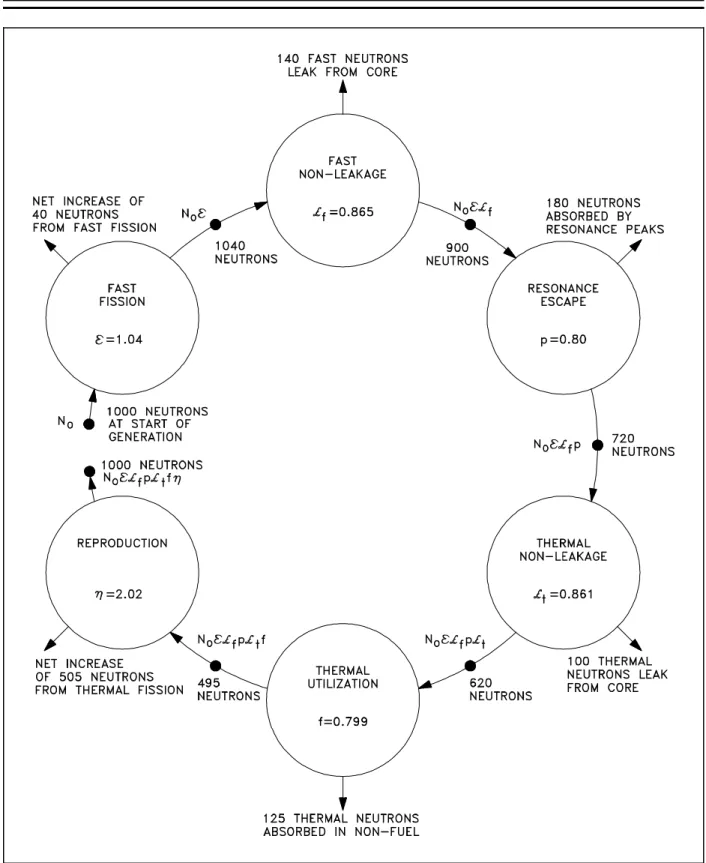
Equation (3-3) is called the six factor formula. Using this six factor formula, it is possible to trace the entire neutron life cycle from production by fission to the initiation of subsequent fissions. Figure 1 illustrates a neutron life cycle with nominal values provided for each of the six factors. Refer to Figure 1 for the remainder of the discussion on the neutron life cycle and sample calculations. The generation begins with 1000 neutrons. This initial number is represented by No. The first process is fast fission and the population has been increased by the neutrons from this fast fission process. From the definition of the fast fission factor it is possible to calculate its value based on the number of neutrons before and after fast fission occur.
number of fast neutrons produced by all fissions number of fast neutrons produced by thermal fissions 1040
1000 1.04
The total number of fast neutrons produced by thermal and fast fission is represented by the quantity No .
Next, it can be seen that 140 neutrons leak from the core before reaching the thermal energy range. The fast non-leakage probability is calculated from its definition, as shown below.
f number of fast neutrons that do not leak from reactor
number of fast neutrons produced by all fissions 1040 140
1040 0.865
The number of neutrons that remain in the core during the slowing down process is represented by the quantity No f.
The next step in the analysis is to consider the number of neutrons that are absorbed in the intermediate energy level. The probability of escaping this resonance absorption (p) is stated as follows.
p number of neutrons that reach thermal energy number of fast neutrons that start to slow down 720
900 0.80
The number of neutrons entering the thermal energy range is now represented by the quantity No f p.
After reaching thermal energies, 100 neutrons leak from the core. The value for t can be calculated by substitution of the known values in the definition as shown below.
t number of thermal neutrons that do not leak from reactor
number of neutrons that reach thermal energies 620
720 0.861
The number of thermal neutrons available for absorption anywhere in the core is represented by the quantity No f p t.
Figure 1 indicates that 125 neutrons were absorbed in non-fuel materials. Since a total of 620 thermal neutrons were absorbed, the number absorbed by the fuel equals 620 - 125 = 495. Therefore, the thermal utilization factor can be calculated as follows.
f number of thermal neutrons absorbed in the fuel number of thermal neutrons absorbed in any reactor material 495
620 0.799
The final factor numerically describes the production of fission neutrons resulting from thermal neutrons being absorbed in the fuel. This factor is called the reproduction factor (η). The value for the reproduction factor can be determined as shown below.
η number of fast neutrons produced by thermal fission number of thermal neutrons absorbed in the fuel 1000
495 2.02
The number of fission neutrons that exist at the end of the life cycle which are available to start a new generation and cycle is represented by the quantity No f p t f η.
In the example illustrated in Figure 1, keff is equal to one. Therefore, 1000 neutrons are available to start the next generation.
Example:
10,000 neutrons exist at the beginning of a generation. The values for each factor of the six factor formula are listed below. Calculate the number of neutrons that exist at the points in the neutron life cycle listed below.
1) Number of neutrons that exist after fast fission.
2) Number of neutrons that start to slow down in the reactor. 3) Number of neutrons that reach thermal energies.
4) Number of thermal neutrons that are absorbed in the reactor. 5) Number of thermal neutrons absorbed in the fuel.
6) Number of neutrons produced from thermal fission. = 1.031 f = 0.889 f = 0.751
p = 0.803 t = 0.905 η = 2.012
Solution:
1) N = No = 10,310 2) N = No f = 9,166 3) N = No f p = 7,360 4) N = No f p t = 6,661 5) N = No f p t f = 5,002 6) N = No f p t f η = 10,065
Neutron Life Cycle of a Fast Reactor
The neutron life cycle in a fast reactor is markedly different than that for a thermal reactor. In a fast reactor, care is taken during the reactor design to minimize thermalization of neutrons. Virtually all fissions taking place in a fast reactor are caused by fast neutrons. Due to this, many factors that are taken into account by the thermal reactor neutron life cycle are irrelevant to the fast reactor neutron life cycle. The resonance escape probability is not significant because very few neutrons exist at energies where resonance absorption is significant. The thermal non-leakage probability does not exist because the reactor is designed to avoid the thermalization of neutrons. A separate term to deal with fast fission is not necessary because all fission is fast fission and is handled by the reproduction factor.
The thermal utilization factor is modified to describe the utilization of fast neutrons instead of thermal neutrons. The reproduction factor is similarly modified to account for fast fission instead of thermal fission.
Sum m ary
Neutron Life Cycle Sum m ary
The infinite multiplication factor, k∞, is the ratio of the neutrons produced by fission
in one generation to the number of neutrons lost through absorption in the preceding generation.
The effective multiplication factor, keff, is the ratio of the number of neutrons produced by fission in one generation to the number of neutrons lost through absorption and leakage in the preceding generation.
Critical is the condition where the neutron chain reaction is self-sustaining and the neutron population is neither increasing nor decreasing.
Subcritical is the condition in which the neutron population is decreasing each generation.
Supercritical is the condition in which the neutron population is increasing each generation.
The six factor formula is stated as keff = f p t f η. Each of the six factors is defined below.
number of fast neutrons produced by all fissions number of fast neutrons produced by thermal fissions
f number of fast neutrons that do not leak from reactor
number of fast neutrons produced by all fissions
p number of neutrons that reach thermal energy number of fast neutrons that start to slow down
t number of thermal neutrons that do not leak from reactor
number of neutrons that reach thermal energies
f number of thermal neutrons absorbed in the fuel number of thermal neutrons absorbed in all reactor materials
η number of fast neutrons produced by thermal fission number of thermal neutrons absorbed in the fuel
Neutron Life Cycle Sum m ary (Cont.)
The thermal utilization factor can be calculated from the macroscopic cross section for absorption of reactor materials using Equation (3-1).
f Σ U a
ΣU a Σ
m a Σ
p a
The reproduction factor can be calculated based on the characteristics of the reactor fuel using Equation (3-2).
η NU235 σ
U235
f ν
U235
NU235 σU235
a N
U238 σU238 a
The number of neutrons present at any point in the neutron life cycle can be calculated as the product of the number of neutrons present at the start of the generation and all the factors preceding that point in the life cycle.
The thermal utilization factor is effected by the enrichment of uranium-235, the amount of neutron poisons, and the moderator-to-fuel ratio.
The reproduction factor is effected by the enrichment of uranium-235.
The resonance escape probability is effected by the enrichment of uranium-235, the temperature of the fuel, and the temperature of the moderator.
An increase in moderator temperature will have the following effects. Increase the thermal utilization factor
Decrease resonance escape probability Decrease fast non-leakage probability Decrease thermal non-leakage probability
REACTIVITY
Reactivity is a measure of the departure of a reactor from criticality. The reactivity is related to the value of keff . Reactivity is a useful concept to predict how the neutron population of a reactor will change over time.
EO 1.8 Given the num ber of neutrons in a reactor core and the effective m ultiplication factor, CALCULATE the num ber of neutrons present after any num ber of generations.
EO 1.9 DEFINE the term reactivity.
EO 1.10 CONVERT between reactivity and the associated value of keff.
EO 1.11 CONVERT m easures of reactivity between the following units: a. ∆∆k/k c. 10- 4 ∆∆k/k
b. %∆∆k/k d. Percent m illirho (pcm ) EO 1.12 EXPLAIN the relationship between reactivity coefficients and
reactivity defects.
Application of the Effective M ultiplication Factor
When keff remains constant from generation to generation, it is possible to determine the number of neutrons beginning any particular generation by knowing only the value of keff and the number of neutrons starting the first generation. If No neutrons start the first generation, then No(keff) neutrons start the second generation. Equation (3-4) can be used to calculate the number of neutrons after the completion of "n" generations.
(3-4) Nn No keff n
Example:
The number of neutrons in the core at time zero is 1000 and keff = 1.002. Calculate the number of neutrons after 50 generations.
Solution:
Use Equation (3-4) to calculate the number of neutrons.
Nn No keff n
N50 1000 neutrons 1.00250 1105 neutrons
Reactivity
If there are No neutrons in the preceding generation, then there are No(keff) neutrons in the present generation. The numerical change in neutron population is (Nokeff - No). The gain or loss in neutron population (Nokeff - No), expressed as a fraction of the present generation (Nokeff), is shown below.
No keff No No keff
This relationship represents the fractional change in neutron population per generation and is referred to as reactivity (ρ). Cancelling out the term No from the numerator and denominator, the reactivity is determined as shown in the equation below.
(3-5) ρ keff 1
keff
From Equation (3-5) it may be seen that ρ may be positive, zero, or negative, depending upon the value of keff. The larger the absolute value of reactivity in the reactor core, the further the reactor is from criticality. It may be convenient to think of reactivity as a measure of a reactor's departure from criticality.
Example:
Calculate the reactivity in the reactor core when keff is equal to 1.002 and 0.998. Solution:
The reactivity for each case is determined by substituting the value of keff into Equation (3-5).
ρ keff 1 keff 1.002 1
1.002 0.001996
ρ keff 1 keff 0.998 1
0.998 0.0020 Units of Reactivity
Reactivity is a dimensionless number. It does not have dimensions of time, length, mass, or any combination of these dimensions. It is simply a ratio of two quantities that are dimensionless. As shown in the calculation in the previous example, the value of reactivity is often a small decimal value. In order to make this value easier to express, artificial units are defined. By definition, the value for reactivity that results directly from the calculation of Equation (3-5) is in units of ∆k/k. Alternative units for reactivity are %∆k/k and pcm (percent millirho). The conversions between these units of reactivity are shown below.
1% ∆k
k 0.01 ∆k
k 1 pcm 0.00001 ∆k
k
Another unit of reactivity that is used at some reactors is equivalent to 10-4 ∆k/k. This unit of reactivity does not have a unique name. Special units for reactivity that do have unique names are dollars and cents. These units and their applications will be described in a later chapter.
Example:
Convert the values of reactivity listed below to the indicated units. a. 0.000421 ∆k/k = pcm
b. 0.0085 ∆k/k = % ∆k/k c. 16 x 10-4 ∆k/k = ∆k/k Solution:
a. 42.1 pcm
b. 0.85% ∆k/k c. 0.0016 ∆k/k
If the reactivity is known, the effective multiplication factor can be determined by solving Equation (3-5) for keff in terms of the reactivity. This results in the following relationship.
(3-6) keff 1
1 ρ
Reactivity must be in units of ∆k/k for use in Equation (3-6). Example:
Given a reactivity of -20.0 x 10⁻⁴ ∆k/k, calculate keff. Solution:
keff 1 1 ρ
1 1 ( 20.0 x 10⁴) 0. 998
Reactivity Coefficients and Reactivity Defects
The amount of reactivity (ρ) in a reactor core determines what the neutron population, and consequently the reactor power, are doing at any given time. The reactivity can be effected by many factors (for example, fuel depletion, temperature, pressure, or poisons). The next several chapters discuss the factors affecting reactivity and how they are used to control or predict reactor behavior.
To quantify the effect that a variation in parameter (that is, increase in temperature, control rod insertion, increase in neutron poison) will have on the reactivity of the core, reactivity coefficients are used. Reactivity coefficients are the amount that the reactivity will change for a given change in the parameter. For instance, an increase in moderator temperature will cause a decrease in the reactivity of the core. The amount of reactivity change per degree change in the moderator temperature is the moderator temperature coefficient. Typical units for the moderator temperature coefficient are pcm/oF. Reactivity coefficients are generally symbolized by αx, where x represents some variable reactor parameter that affects reactivity. The definition of a reactivity coefficient in equation format is shown below.
αx ∆ ρ ∆x
If the parameter x increases and positive reactivity is added, then αx is positive. If the parameter x increases and negative reactivity is added, then αx is negative.
Reactivity defects (∆ρ) are the total reactivity change caused by a variation in a parameter. Reactivity defects can be determined by multiplying the change in the parameter by the average value of the reactivity coefficient for that parameter. The equation below shows the general method for relating reactivity coefficients to reactivity defects.
∆ρ = αx ∆x Example:
The moderator temperature coefficient for a reactor is -8.2 pcm/oF. Calculate the reactivity defect that results from a temperature decrease of 5oF.
Solution:
∆ ρ αT ∆T 8.2 pcm
°F 5 °F 41 pcm
The reactivity addition due to the temperature decrease was positive because of the negative temperature coefficient.
Sum m ary
The important information in this chapter is summarized below.
Reactivity Sum m ary
The number of neutrons present in the core after a given number of generations is calculated using Equation (3-4).
Nn No keff n
Reactivity is the fractional change in neutron population per generation.
Reactivity and keff are represented in Equation (3-5) and Equation (3-6), respectively.
ρ keff 1
keff keff 1 1 ρ
The relationship between units of reactivity are listed below.
1% ∆k
k 0.01 ∆k k 1 pcm 0.00001 ∆k
k
A reactivity coefficient is the amount of change in reactivity per unit change in the parameter. A reactivity defect is the total reactivity change caused by a change in the parameter. The reactivity defect is the product of the reactivity coefficient and the magnitude of the parameter change.
REACTIVITY C OEFFICIENTS
Changes in the physical properties of the materials in the reactor will result in changes in the reactivity. Reactivity coefficients are useful in quantifying the reactivity change that will occur due to the change in a physical property such as the temperature of the moderator or fuel.
EO 2.1 EXPLAIN the conditions of over m oderation and under m oderation.
EO 2.2 EXPLAIN why m any reactors are designed to be operated in an under m oderated condition.
EO 2.3 STATE the effect that a change in m oderator tem perature will have on the m oderator to fuel ratio.
EO 2.4 DEFINE the tem perature coefficient of reactivity.
EO 2.5 EXPLAIN why a negative tem perature coefficient of reactivity is desirable.
EO 2.6 EXPLAIN why the fuel tem perature coefficient is m ore effective than the m oderator tem perature coefficient in term inating a rapid power rise.
EO 2.7 EXPLAIN the concept of Doppler broadening of resonance absorption peaks.
EO 2.8 LIST two nuclides that are present in som e types of reactor fuel assem blies that have significant resonance absorption peaks.
EO 2.9 DEFINE the pressure coefficient of reactivity.
EO 2.10 EXPLAIN why the pressure coefficient of reactivity is usually negligible in a reactor cooled and m oderated by a subcooled liquid.
EO 2.11 DEFINE the void coefficient of reactivity.
EO 2.12 IDENTIFY the m oderator conditions under which the void coefficient of reactivity becom es significant.
M oderator Effects
As discussed in the previous module, a moderator possesses specific desirable characteristics. (a) large neutron scattering cross section
(b) low neutron absorption cross section (c) large neutron energy loss per collision
With the exception of the Liquid Metal Fast Breeder Reactor (LMFBR), the remaining major reactor types that are currently employed use moderating materials to reduce fission neutron energies to the thermal range. Light moderators (composed of light nuclei) are found to be more effective than heavy moderators because the light moderator removes more energy per collision than a heavy moderator. Therefore, the neutrons reach thermal energy more rapidly and they are less likely to be lost through resonance absorption.
As discussed in a previous module, the ability of a given material to slow down neutrons is referred to as the macroscopic slowing down power (MSDP) and is defined as the product of the logarithmic energy decrement per collision (ξ) times the macroscopic scattering cross section for neutrons as follows.
M S D P ξ Σs
Macroscopic slowing down power indicates how rapidly slowing down occurs in the material in question, but it does not completely define the effectiveness of the material as a moderator. An element such as boron has a high logarithmic energy decrement and a good slowing down power, but is a poor moderator. It is a poor moderator because of its high probability of absorbing neutrons, and may be accounted for by dividing the macroscopic slowing down power by the macroscopic absorption cross section. This relationship is called the moderating ratio (MR).
M R ξ Σs Σa
The moderating ratio is merely the ratio of slowing down power to the macroscopic absorption cross section. The higher the moderating ratio, the more effectively the material performs as a moderator.
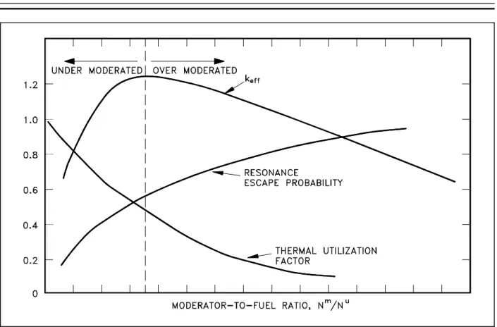
Another ratio, the moderator-to-fuel ratio (Nm/Nu), is very important in the discussion of moderators. As the reactor designer increases the amount of moderator in the core (that is, Nm/Nu increases), neutron leakage decreases. Neutron absorption in the moderator (Σma) increases and causes a decrease in the thermal utilization factor. Having insufficient moderator in the core (that is, Nm/Nu decreases) causes an increase in slowing down time and results in a greater loss of neutrons by resonance absorption. This also causes an increase in neutron leakage. The
Because the moderator-to-fuel ratio affects the thermal utilization factor and the resonance escape Figure 2 Effects of Over and Under Moderation on keff
probability, it also affects keff. The remaining factors in the six factor formula are also affected by the moderator-to-fuel ratio, but to a lesser extent than f and p. As illustrated in Figure 2, which is applicable to a large core fueled with low-enriched fuel, there is an optimum point above which increasing the moderator-to-fuel ratio decreases keff due to the dominance of the decreasing thermal utilization factor. Below this point, a decrease in the moderator-to-fuel ratio decreases keff due to the dominance of the increased resonance absorption in the fuel. If the ratio is above this point, the core is said to be over moderated, and if the ratio is below this point, the core is said to be under moderated.
In practice, water-moderated reactors are designed with a moderator-to-fuel ratio so that the reactor is operated in an under moderated condition. The reason that some reactors are designed to be under moderated is if the reactor were over moderated, an increase in temperature would decrease the Nm/Nu due to the expansion of the water as its density became lower. This decrease in Nm/Nu would be a positive reactivity addition, increasing keff and further raising power and temperature in a dangerous cycle. If the reactor is under moderated, the same increase in temperature results in the addition of negative reactivity, and the reactor becomes more self-regulating.
M oderator Tem perature Coefficient
The change in reactivity per degree change in temperature is called the temperature coefficient of reactivity. Because different materials in the reactor have different reactivity changes with temperature and the various materials are at different temperatures during reactor operation, several different temperature coefficients are used. Usually, the two dominant temperature coefficients are the moderator temperature coefficient and the fuel temperature coefficient. The change in reactivity per degree change in moderator temperature is called the moderator
temperature coefficient of reactivity. The magnitude and sign (+ or -) of the moderator
temperature coefficient is primarily a function of the moderator-to-fuel ratio. If a reactor is under moderated, it will have a negative moderator temperature coefficient. If a reactor is over moderated, it will have a positive moderator temperature coefficient. A negative moderator temperature coefficient is desirable because of its self-regulating effect. For example, an increase in reactivity causes the reactor to produce more power. This raises the temperature of the core and adds negative reactivity, which slows down, or turns, the power rise.
Fuel Tem perature Coefficient
Another temperature coefficient of reactivity, the fuel temperature coefficient, has a greater effect than the moderator temperature coefficient for some reactors. The fuel temperature coefficient
is the change in reactivity per degree change in fuel temperature. This coefficient is also called the "prompt" temperature coefficient because an increase in reactor power causes an immediate change in fuel temperature. A negative fuel temperature coefficient is generally considered to be even more important than a negative moderator temperature coefficient because fuel temperature immediately increases following an increase in reactor power. The time for heat to be transferred to the moderator is measured in seconds. In the event of a large positive reactivity insertion, the moderator temperature cannot turn the power rise for several seconds, whereas the fuel temperature coefficient starts adding negative reactivity immediately.
Another name applied to the fuel temperature coefficient of reactivity is the fuel doppler reactivity coefficient. This name is applied because in typical low enrichment, light water-moderated, thermal reactors the fuel temperature coefficient of reactivity is negative and is the result of the doppler effect, also called doppler broadening. The phenomenon of the doppler effect is caused by an apparent broadening of the resonances due to thermal motion of nuclei as illustrated in Figure 3. Stationary nuclei absorb only neutrons of energy Eo. If the nucleus is moving away from the neutron, the velocity (and energy) of the neutron must be greater than Eo to undergo resonance absorption. Likewise, if the nucleus is moving toward the neutron, the neutron needs less energy than Eo to be absorbed. Raising the temperature causes the nuclei to vibrate more rapidly within their lattice structures, effectively broadening the energy range of
Pressure Coefficient
Figure 3 Effect of Fuel Temperature on Resonance Absorption Peaks
The reactivity in a reactor core can be affected by the system pressure. The pressure coefficient
of reactivity is defined as the change in reactivity per unit change in pressure. The pressure coefficient of reactivity for the reactor is the result of the effect of pressure on the density of the moderator. For this reason, it is sometimes referred to as the moderator density reactivity coefficient. As pressure increases, density correspondingly increases, which increases the moderator-to-fuel ratio in the core. In the typical under moderated core the increase in the moderator-to-fuel ratio will result in a positive reactivity addition. In reactors that use water as a moderator, the absolute value of the pressure reactivity coefficient is seldom a major factor because it is very small compared to the moderator temperature coefficient of reactivity. Void Coefficient
In systems with boiling conditions, such as boiling water reactors (BWR), the pressure coefficient becomes an important factor due to the larger density changes that occur when the vapor phase of water undergoes a pressure change. Of prime importance during operation of a BWR, and a factor in some other water-moderated reactors, is the void coefficient. The void coefficient is caused by the formation of steam voids in the moderator. The void coefficient of reactivity is defined as the change in reactivity per percent change in void volume. As the reactor power is raised to the point where the steam voids start to form, voids displace moderator from the coolant channels within the core. This displacement reduces the moderator-to-fuel ratio, and in an under moderated core, results in a negative reactivity addition, thereby limiting reactor power rise. The void coefficient is significant in water-moderated reactors that operate at or near saturated conditions.
Sum m ary
The important information in this chapter is summarized below.
Reactivity Coefficients Sum m ary
The temperature coefficient of reactivity is the change in reactivity per degree change in temperature.
A reactor is under moderated when a decrease in the moderator-to-fuel ratio decreases keff due to the increased resonance absorption. A reactor is over moderated when an increase in the moderator-to-fuel ratio decreases keff due to the decrease in the thermal utilization factor.
Reactors are usually designed to operate in an under moderated condition so that the moderator temperature coefficient of reactivity is negative.
Increasing the moderator temperature will decrease the moderator-to-fuel ratio. Decreasing the moderator temperature will increase the moderator-to-fuel ratio. A negative temperature coefficient of reactivity is desirable because it makes the reactor more self-regulating. An increase in power, resulting in an increase in temperature, results in negative reactivity addition due to the temperature coefficient. The negative reactivity addition due to the temperature increase will slow or stop the power increase.
The fuel temperature coefficient is more effective than the moderator temperature coefficient in terminating a rapid power rise because the fuel temperature immediately increases following a power increase, while the moderator temperature does not increase for several seconds.
The Doppler broadening of resonance peaks occurs because the nuclei may be moving either toward or away from the neutron at the time of interaction. Therefore, the neutron may actually have either slightly more or slightly less than the resonant energy, but still appear to be at resonant energy relative to the nucleus.
Uranium-238 and plutonium-240 are two nuclides present in some reactor fuels that have large resonance absorption peaks.
Reactivity Coefficients Sum m ary (Cont.)
The pressure coefficient of reactivity is the change in reactivity per unit change in pressure.
The pressure coefficient of reactivity is usually negligible in reactors moderated by subcooled liquids because the density of the liquid does not change significantly within the operating pressure range.
The void coefficient of reactivity is the change in reactivity per unit change in void volume.
The void coefficient of reactivity becomes significant in a reactor in which the moderator is at or near saturated conditions.
NEUTRON P OISON S
In some reactors, neutron-absorbing materials called poisons are intentionally designed into the reactor for specific purposes. Some of these poisons deplete as they absorb neutrons during reactor operation, and others remain relatively constant.
EO 3.1 DEFINE the following term s: a. Burnable poison b. Non-burnable poison c. Chem ical shim
EO 3.2 EXPLAIN the use of burnable neutron poisons in a reactor core.
EO 3.3 LIST the advantages and disadvantages of chem ical shim over fixed burnable poisons.
EO 3.4 STATE two reasons why fixed non-burnable neutron poisons are used in reactor cores.
EO 3.5 STATE an exam ple of a m aterial used as a fixed non-burnable neutron poison.
Fixed B urnable Poisons
During operation of a reactor the amount of fuel contained in the core constantly decreases. If the reactor is to operate for a long period of time, fuel in excess of that needed for exact criticality must be added when the reactor is built. The positive reactivity due to the excess fuel must be balanced with negative reactivity from neutron-absorbing material. Moveable control rods containing neutron-absorbing material are one method used to offset the excess fuel. Control rods will be discussed in detail in a later chapter. Using control rods alone to balance the excess reactivity may be undesirable or impractical for several reasons. One reason for a particular core design may be that there is physically insufficient room for the control rods and their large mechanisms.