ThinkCentre
User Guide
Machine Types:
0800, 0852, 0870, 2471, 2557, 3091, 3265, 3373,
ThinkCentre
User Guide
Machine Types:
0800, 0852, 0870, 2471, 2557, 3091, 3265, 3373,
Note: Before using this information and the product it supports, be sure to read and understand the
ThinkCentre Safety and Warranty Guideand Appendix A “Notices” on page 79.
© Copyright Lenovo
Second Edition (May 2011) 2011.
Contents
Important safety information . . . v
Chapter 1. Product overview . . . 1
Features . . . 1
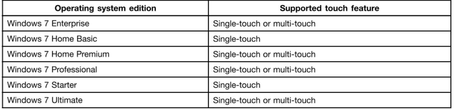
Single-touch and multi-touch feature . . . 3
Specifications . . . 4
Software overview . . . 6
Software provided with your Windows operating system . . . 6
Locating computer controls, connectors, and parts . . . 7
Front view. . . 8
Rear view . . . 9
Component locations . . . 11
System board part and connector locations . 12
Chapter 2. Installing or replacing
hardware . . . .
15
Installing or replacing hardware . . . 15
Installing external options . . . 15
Installing a computer wall mount . . . 15
Removing the computer cover. . . 15
Removing or reinstalling the frame stand . . 16
Removing or reinstalling the lift stand . . . . 17
Removing or reinstalling the rear I/O assembly cover . . . 19
Removing or reinstalling the VESA frame cover . . . 20
Removing or reinstalling the VESA frame . . 21
Installing or replacing a memory module . . . 22
Replacing the battery . . . 24
Replacing the hard disk drive . . . 25
Replacing the optical drive . . . 28
Replacing the heat sink . . . 29
Replacing the microprocessor . . . 32
Replacing the WI-FI card . . . 34
Replacing the Bluetooth module . . . 35
Replacing the multi-touch board . . . 36
Replacing the ambient light sensor . . . 37
Replacing the ExpressCard . . . 39
Replacing the internal speakers . . . 40
Replacing the integrated camera with microphone . . . 41
Replacing the microprocessor fan assembly . 42 Replacing the card reader . . . 44
Replacing the rear I/O assembly . . . 45
Replacing the right I/O assembly. . . 46
Replacing the power supply . . . 47
Replacing the keyboard . . . 49
Replacing the mouse . . . 50
Completing the parts replacement . . . 52
Obtaining device drivers . . . 53
Basic security features . . . 53
Integrated cable lock . . . 53
Password protection . . . 54
Erasing lost or forgotten passwords (clearing CMOS) . . . 54
Chapter 3. Recovery information. . .
57
Creating and using recovery media . . . 57
Creating recovery media . . . 57
Using recovery media . . . 57
Performing backup and recovery operations . . . 58
Performing a backup operation . . . 58
Performing a recovery operation . . . 59
Using the Rescue and Recovery workspace . . . 59
Creating and using a rescue medium . . . 60
Creating a rescue medium . . . 60
Using a rescue medium . . . 61
Installing or reinstalling device drivers . . . 61
Solving recovery problems . . . 62
Chapter 4. Using the Setup Utility
program . . . .
63
Starting the Setup Utility program . . . 63
Viewing or changing settings . . . 63
Using passwords. . . 63
Password considerations . . . 64
Administrator password . . . 64
Power-on password . . . 64
Hard disk drive password . . . 64
Setting, changing, or deleting a password . . 64
Enabling or disabling a device . . . 65
Selecting a startup device . . . 65
Selecting a temporary startup device . . . . 65
Viewing or changing the startup device sequence . . . 65
Exiting the Setup Utility program . . . 66
Chapter 5. Updating system
programs . . . .
67
Using system programs . . . 67
Updating (flashing) the BIOS from a disc . . . . 67
Updating (flashing) the BIOS from your operating system . . . 68
iii
Recovering from a POST/BIOS update failure . . 68
Chapter 6. Troubleshooting and
diagnostic programs . . . .
71
Basic troubleshooting . . . 71
Diagnostic programs . . . 72
Lenovo ThinkVantage Toolbox . . . 72
PC-Doctor for Rescue and Recovery . . . . 73
PC-Doctor for DOS . . . 73
Cleaning an optical mouse . . . 74
Chapter 7. Getting information, help,
and service . . . .
75
Information resources . . . 75
Online Books folder . . . 75
Lenovo ThinkVantage Tools . . . 75
ThinkVantage Productivity Center . . . 75
Lenovo Welcome . . . 76
Access Help . . . 76
Safety and warranty . . . 76
Lenovo Web site (http://www.lenovo.com) . . 76
Help and service . . . 77
Using the documentation and diagnostic programs . . . 77
Calling for service. . . 77
Using other services . . . 78
Purchasing additional services . . . 78
Appendix A. Notices . . . .
79
Television output notice . . . 80
European conformance CE mark . . . 80
Trademarks . . . 80
Important safety information
CAUTION:Before using this manual, be sure to read and understand all the related safety information for this product. Refer to theThinkCentre Safety and Warranty Guidethat you received with this product for the latest safety information. Reading and understanding this safety information reduces the risk of personal injury and or damage to your product.
If you no longer have a copy of theThinkCentre Safety and Warranty Guide, you can obtain a Portable Document Format (PDF) version from the Lenovo®Support Web site at:
http://www.lenovo.com/support
v
Chapter 1. Product overview
This chapter provides information about the computer features, specifications, preinstalled software programs, and connector and part locations.
This chapter contains the following topics:
• “Features” on page 1: This section provides information about the computer features. • “Specifications” on page 4: This section lists the physical specifications for your computer.
• “Software overview” on page 6: This section provides information about the software programs provided with your computer.
• “Locating computer controls, connectors, and parts” on page 7: This section provides information to help you locate your computer controls, connectors and parts.
Features
This section provides information about the computer features. System information
The following information covers a variety of models. For information about your specific model, use the Setup Utility program. See Chapter 4 “Using the Setup Utility program” on page 63.
Microprocessor
Your computer comes with one of the following microprocessors (internal cache size varies by model type): • Intel®Core™ i3 microprocessor
• Intel Core i5 microprocessor • Intel Pentium®microprocessor Memory module(s)
• Supports up to two double data rate 3 dual inline memory modules (DDR3 DIMMs)
Note: Your computer supports both 1066 MHz and 1333 MHz DDR3 memory modules. However, if you are using the 1333 MHz memory module(s) with a microprocessor that runs at 1066 MHz (such as the Intel Pentium G6950 microprocessor), your memory module(s) will operate at 1066 MHz.
Internal drives
• One slim Serial Advanced Technology Attachment (SATA) optical drive • One SATA hard disk drive
Video subsystem
• Integrated graphics card for a Video Graphics Array (VGA) IN connector and a DisplayPort out connector Audio subsystem
• Integrated high-definition (HD) audio
• Microphone connector and headphone connector • Internal speakers
Connectivity
• 10/100/1000 Mbps Ethernet controller System management features
• Ability to store the power-on self-test (POST) hardware test results • Advanced Configuration and Power Interface (ACPI) support • Automatic power-on startup
• Desktop Management Interface (DMI)
• Intel Active Management Technology (AMT) (available in some models) • Intel Rapid Storage Technology
• Preboot Execution Environment (PXE)
• System Management (SM) Basic Input/Output System (BIOS) and SM software • Wake on LAN
• Windows Management Instrumentation (WMI) Input/Output(I/O)features
• One DisplayPort connector • One Ethernet connector • One optional 9-pin serial port • One optional card reader • One optional ExpressCard slot
• One optional Personal System/2®(PS/2®) keyboard connector • One optional PS/2 mouse connector
• One VGA IN connector
• Six Universal Serial Bus (USB) connectors
• Two audio connectors (microphone connector and headphone connector) • Wireless keyboard and mouse (available in some models)
For more information about I/O features, see “Rear view” on page 9. Expansion
• One hard disk drive bay • One optical drive bay Power supply
• 150-watt auto-sensing power supply Security features
Chapter 1. Product overview
This chapter provides information about the computer features, specifications, preinstalled software programs, and connector and part locations.
This chapter contains the following topics:
• “Features” on page 1: This section provides information about the computer features. • “Specifications” on page 4: This section lists the physical specifications for your computer.
• “Software overview” on page 6: This section provides information about the software programs provided with your computer.
• “Locating computer controls, connectors, and parts” on page 7: This section provides information to help you locate your computer controls, connectors and parts.
Features
This section provides information about the computer features. System information
The following information covers a variety of models. For information about your specific model, use the Setup Utility program. See Chapter 4 “Using the Setup Utility program” on page 63.
Microprocessor
Your computer comes with one of the following microprocessors (internal cache size varies by model type): • Intel®Core™ i3 microprocessor
• Intel Core i5 microprocessor • Intel Pentium®microprocessor Memory module(s)
• Supports up to two double data rate 3 dual inline memory modules (DDR3 DIMMs)
Note: Your computer supports both 1066 MHz and 1333 MHz DDR3 memory modules. However, if you are using the 1333 MHz memory module(s) with a microprocessor that runs at 1066 MHz (such as the Intel Pentium G6950 microprocessor), your memory module(s) will operate at 1066 MHz.
Internal drives
• One slim Serial Advanced Technology Attachment (SATA) optical drive • One SATA hard disk drive
Video subsystem
• Integrated graphics card for a Video Graphics Array (VGA) IN connector and a DisplayPort out connector Audio subsystem
• Integrated high-definition (HD) audio
• Microphone connector and headphone connector • Internal speakers
1
Table 1. Operating system edition and supported touch feature
Operating system edition Supported touch feature
Windows 7 Enterprise Single-touch or multi-touch
Windows 7 Home Basic Single-touch
Windows 7 Home Premium Single-touch or multi-touch Windows 7 Professional Single-touch or multi-touch
Windows 7 Starter Single-touch
Windows 7 Ultimate Single-touch or multi-touch
Specifications
Computer dimensions (without a stand and frame foot)
Width: 560 mm (22.05 inches) Height: 392 mm (15.43 inches)
Depth: 79 mm (3.11 inches) or 86 mm (3.39 inches) (varies by configuration)
Computer dimensions (with a stand and frame foot)
• Width: 560 mm (22.05 inches) • Maximum height:
– 421.9 mm (16.61 inches) (with a frame stand and frame foot) – 566.9 mm (22.32 inches) (with a lift stand)
• Depth: ranges from 109 mm (4.29 inches) to 250 mm (9.84 inches) (varies by configuration)
Computer weight
Maximum configuration as shipped: 14.1 kg (31.09 lbs)
Touch screen dimensions
Width: 531.4 mm (20.92 inches) Height: 311.6 mm (12.27 inches) Depth: 2 mm (0.08 inch)
Lift stand
Height adjustment: 110 mm (4.33 inches) Tilt adjustment: -5° to 25°from the vertical
Frame stand
Tilt adjustment: 15°to 45° from the vertical
Environment
• Air temperature:
Operating: 10°C to 35°C (50°F to 95°F)
Non-operating: -20°C to 60°C (-4°F to 140°F) (with package) • Humidity:
Operating: 20% to 80% (10% per hour, non-condensing) Non-operating: 20% to 80% (10% per hour, non-condensing) • Altitude:
Operating: -50 to 10 000 ft (-15.2 to 3 048 m) Non-operating: -50 to 35 000 ft (-15.2 to 10 668 m)
Electrical input
• Input voltage: – Low range:
Minimum: 100 V ac Maximum: 127 V ac
Input frequency range: 50 to 60 Hz – High range:
Minimum: 200 V ac Maximum: 240 V ac
Input frequency range: 50 to 60 Hz
Software overview
The computer comes with a preinstalled operating system and several preinstalled applications.
Software provided with your Windows operating system
This section provides information about the software provided with your Windows operating system.
Software provided by Lenovo
The following software programs are provided by Lenovo to help you improve productivity and reduce the cost associated with maintaining your computer. Software programs provided with your computer might vary depending on your model type and preinstalled operating system.
Lenovo ThinkVantage Tools
The Lenovo ThinkVantage®Tools program guides you to a host of information sources and provides easy access to various tools to help you work more easily and securely. For more information, see “Lenovo ThinkVantage Tools” on page 75.
ThinkVantage Productivity Center
The ThinkVantage Productivity Center program guides you to a host of information sources and tools to help you set up, understand, and maintain your computer, and enhance your computer performance. For more information, see “ThinkVantage Productivity Center” on page 75.
Note: The ThinkVantage Productivity Center program is only available on computers preinstalled with the Windows Vista operating system from Lenovo.
Lenovo Welcome
The Lenovo Welcome program introduces some innovative built-in features of Lenovo to you and guides you through some important setup tasks to help you make the most of your computer.
Product Recovery
The Product Recovery program enables you to restore the contents of the hard disk drive to the factory default settings.
ThinkVantage Rescue and Recovery
The ThinkVantage Rescue and Recovery®program is a one button recovery and restore solution that includes a set of self-recovery tools to help you diagnose computer problems, get help, and recover from system crashes, even if you cannot start the Windows operating system.
Power Manager
The Power Manager program provides convenient, flexible, and complete power management for your ThinkCentre®computer. By using the Power Manager program, you can adjust your power settings to achieve the best balance between system performance and power saving.
Password Manager
The Password Manager program helps you automatically capture and fill in authentication information for Windows applications and Web sites.
provided by Lenovo, such as the Rescue and Recovery program and the ThinkVantage Productivity Center program.
Lenovo ThinkVantage Toolbox
The Lenovo ThinkVantage Toolbox program helps you maintain your computer, improve computing security, diagnose computer problems, get familiar with the innovative technologies provided by Lenovo, and get more information about your computer. For more information, see “Lenovo ThinkVantage Toolbox” on page 72.
PC-Doctor for Rescue and Recovery
The PC-Doctor for Rescue and Recovery diagnostic program is preinstalled on your ThinkCentre computer as part of the Rescue and Recovery workspace to help you diagnose hardware problems. It can also report operating-system-controlled settings that interfere with the correct operation of your system. Use the PC-Doctor for Rescue and Recovery diagnostic program if you are unable to start the Windows operating system. For more information, see “PC-Doctor for Rescue and Recovery” on page 73.
Adobe Reader
The Adobe Reader program is a tool used to view, print, and search PDF documents.
See “Online Books folder” on page 75 for more information about accessing and viewing the publications.
Antivirus software
Your computer comes with antivirus software that you can use to detect and eliminate viruses. Lenovo provides a full version of antivirus software on your computer with a free 30-day subscription. After 30 days, you must renew the license to continue receiving the antivirus software updates.
For more information about how to use your antivirus software, refer to the help system of your antivirus software.
Locating computer controls, connectors, and parts
This section provides information to help you locate your computer controls, connectors, and parts.
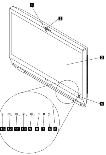
Front view
Figure 1 “Front control and part locations” on page 8 shows the locations of the controls and parts on the front of your computer.
Figure 1. Front control and part locations
1 Integrated camera with microphone (MIC) (available in some models)
8 Wireless activity indicator
2 Integrated camera on/off button 9 Menu/Enter
3 Liquid crystal display (LCD) panel 10 Brightness control /Right
4 Power switch 11 Image setup control /Left
5 Power indicator 12 Monitor mode control /Exit
6 Hard disk drive activity indictor 13 Microphone mute/on control
To use your computer in monitor mode, you need to have a second computer. Connect one end of the VGA cable to the VGA IN connector on the rear of your computer, and the other end to the VGA connector on the second computer. Use the monitor mode control on the front of your computer to switch your computer between computer mode and monitor mode.
The following table shows the functions of each control when your computer works in computer mode or monitor mode.
Icon Control Description
Menu Open the main On-Screen Display (OSD) menu. Enter Confirm a selection.
Brightness control Adjust overall monitor brightness. Right Move to the right.
Image setup control Automatically optimize the image. Left Move to the left.
Cancel/Exit Cancel an operation or exit the main OSD menu.
Monitor mode control Switch your computer between computer mode and monitor mode.
Rear view
Figure 2 “Rear connector locations” on page 9 shows the locations of the connectors on the rear of your computer. Some connectors on the rear of your computer are color-coded to help you determine where to connect the cables on your computer.
Figure 2. Rear connector locations
1 Card reader (available in some models) 9 Power cord connector
2 USB connector 10 Integrated cable lock slot
3 Headphone connector 11 Ethernet connector
4 Microphone connector 12 USB connectors (4)
5 USB connector 13 DisplayPort out connector
6 Serial port (available in some models) 14 VGA IN connector
7 PS/2 mouse connector (available in some models) 15 ExpressCard slot (available in some models)
8 PS/2 keyboard connector (available in some models)
Connector Description
DisplayPort out connector Used to attach a high-performance monitor, a direct-drive monitor, or other devices that use a DisplayPort connector.
Ethernet connector Used to attach an Ethernet cable for a local area network (LAN).
Note: To operate the computer within FCC Class B limits, use a Category 5 Ethernet cable.
Microphone connector Used to attach a microphone to your computer when you want to record sound or if you use speech-recognition software.
PS/2 keyboard connector (optional)
Used to attach a keyboard that uses a PS/2 keyboard connector. PS/2 mouse connector
(optional)
Used to attach a mouse, a trackball, or other pointing devices that use a PS/2 mouse connector.
Serial port (optional) Used to attach an external modem, a serial printer, or other devices that use a 9-pin serial port.
USB connector Used to attach a device that requires a USB connector, such as a USB keyboard, a USB mouse, a USB scanner, or a USB printer. If you have more than eight USB devices, you can purchase a USB hub, which you can use to connect additional USB devices. VGA IN connector Used to connect your computer to a VGA monitor connector on a second computer so
Component locations
Figure 3 “Component locations” on page 11 shows the locations of the various components in your computer. To remove the computer cover and access the inside of the computer, see “Removing the computer cover” on page 15.
Figure 3. Component locations
1 Frame stand 15 Internal speaker
2 Video Electronics Standards Association (VESA) frame cover
16 Frame foot
3 Fan duct 17 Hard disk drive
4 Heat sink 18 Right I/O assembly
5 Memory modules (2) 19 Card reader*
6 WI-FI card* 20 Optical drive bay
7 Microprocessor fan 21 Inverter
8 Battery 22 Computer main bracket
9 ExpressCard* 23 Optical drive*
10 Rear I/O assembly 24 Power supply
11 Internal speaker 25 Integrated camera with microphone*
12 Bluetooth module* 26 Ambient light sensor*
13 System fan 27 Multi-touch board*
14 Rear I/O assembly cover 28 VESA frame
Notes:
1. * denotes optional parts, which are available in some models.
2. Your computer might come with a frame stand or a lift stand. For more information about the lift stand, see “Removing or reinstalling the lift stand” on page 17.
System board part and connector locations
Figure 4 “System board part and connector locations” on page 12 shows the locations of the parts and connectors on the system board.
Figure 4. System board part and connector locations
1 Microprocessor 15 Rear I/O assembly connector
7 Bluetooth module cable connector 21 SATA connector
8 Wireless keyboard and mouse connector 22 SATA connector
9 Clear Complementary Metal Oxide Semiconductor (CMOS) /Recovery jumper
23 Optical drive power connector
10 Battery 24 Low-voltage differential signaling (LVDS) cable connector
11 Microprocessor fan connector 25 System fan connector
12 Internal speaker cable connector 26 Inverter connector
13 Power switch cable connector 27 Power supply fan connector
14 ExpressCard connector 28 Power supply connector
Chapter 2. Installing or replacing hardware
This chapter provides instructions on how to install or replace hardware for your computer. This chapter contains the following topics:
• “Installing or replacing hardware” on page 15 • “Obtaining device drivers” on page 53 • “Basic security features” on page 53
Installing or replacing hardware
This section provides instructions on how to install or replace hardware for your computer. You can maintain your computer or expand the capabilities of your computer by installing or replacing hardware.
Notes:
1. Use only computer parts provided by Lenovo.
2. When installing or replacing an option, use the appropriate instructions in this section along with the instructions that come with the option.
Installing external options
You can install external options to your computer, such as external speakers, a printer, or a scanner. For some external options, you must install additional software in addition to making the physical connection. When you install an external option, see “Locating computer controls, connectors, and parts” on page 7 to identify the required connector. Then, use the instructions that come with the option to help you make the connection and install any software or device drivers that are required for the option.
Installing a computer wall mount
CAUTION:
If you wish to perform a self installation of a wall mounting unit for this product, Lenovo recommends that you select a wall mount product that is certified by Underwriters Laboratories (UL), Intertek (ETL), the Canadian Standards Association (CSA NRTL), TUV Rheinland of North America (TUV US), or any other safety test laboratory that is recognized by the United States Occupational Safety and Health Administration (OSHA). To avoid the risk of personal injury or damage to equipment, self installers should ensure that the weight bearing capacity of the wall mount product is rated above 12 kg (26. 5 lbs), so that it can support the machine for long time operation safely.
Your computer supports VESA standard 100 mm × 100 mm (3.94 inches × 3.94 inches) wall mounts. For proper mounting, use four screws of the following specifications:
Diameter × Pitch × Length: 4 mm × 0.7 mm × 10 mm (0.16 inch × 0.03 inch × 0.39 inch)
Note:When installing a computer wall mount, make sure that you leave at least a 60 mm (2.36 inches) space between the wall and your computer for easy access to the connectors on the rear of your computer.
Removing the computer cover
Attention:
Do not open your computer or attempt any repair before reading and understanding the “Important safety information” in theThinkCentre Safety and Warranty Guidethat came with your computer. To obtain a copy of theThinkCentre Safety and Warranty Guide, go to:
http://www.lenovo.com/support
15
This section provides instructions on how to remove the computer cover. CAUTION:
Turn off the computer and wait three to five minutes to let the computer cool before removing the computer cover.
To remove the computer cover, do the following:
1. Remove all media from the drives and turn off all attached devices and the computer. Then, disconnect all power cords from electrical outlets and disconnect all cables that are connected to the computer. 2. Place a soft, clean towel or cloth on the desk or surface. Hold the sides of your computer and gently lay
it down so that the screen is against the surface and the cover is facing up.
3. Remove any locking device that secures the computer cover, such as an integrated cable lock. See “Integrated cable lock” on page 53.
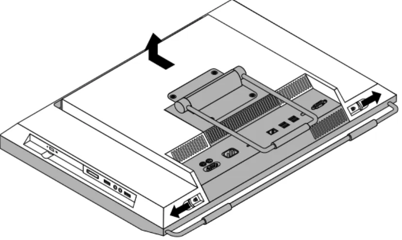
4. Press the two cover-release buttons on the computer cover as shown, slide the computer cover toward the top of the computer, and then lift the computer cover up to remove it from the chassis.
Figure 5. Removing the computer cover
Removing or reinstalling the frame stand
Your computer might come with a frame stand or a lift stand. This section provides instructions on how to remove or reinstall the frame stand. For information about the lift stand, see “Removing or reinstalling the lift stand” on page 17.
To remove or reinstall the frame stand, do the following:
1. Remove all media from the drives and turn off all attached devices and the computer. Then, disconnect all power cords from electrical outlets and disconnect all cables that are connected to the computer. 2. Place a soft, clean towel or cloth on the desk or surface. Hold the sides of your computer and gently lay
3. Remove the four screws that secure the frame stand. Keep the four screws, and put them aside. You will need them when installing the frame stand.
Figure 6. Removing the frame stand
4. Lift the frame stand off the computer and put it in a safe place.
5. To reinstall the frame stand, position the frame stand so that the four screw holes align with those in the computer VESA frame and then install the four screws to secure the frame stand.
What to do next:
• To work with another piece of hardware, go to the appropriate section.
• To complete the installation or replacement, go to “Completing the parts replacement” on page 52.
Removing or reinstalling the lift stand
Your computer might come with a lift stand or a frame stand. This section provides instructions on how to remove or reinstall the lift stand. For information about the frame stand, see “Removing or reinstalling the frame stand” on page 16.
To remove or reinstall the lift stand, do the following:
1. Remove all media from the drives and turn off all attached devices and the computer. Then, disconnect all power cords from electrical outlets and disconnect all cables that are connected to the computer. 2. Place a soft, clean towel or cloth on the desk or surface. Hold the sides of your computer and gently lay
it down so that the screen is against the surface and the cover is facing up.
3. Remove the three screws that secure the lift stand. Keep the three screws, and put them aside. You will need them when installing the lift stand. Remove the lift stand from the computer.
4. To reinstall the lift stand, insert the two tabs 1 on the lift stand into the corresponding holes in the computer VESA frame, and then slide the lift stand toward the bottom of the computer. Align the three screw holes in the lift stand with those in the computer VESA frame and then install the three screws to secure the lift stand.
Figure 8. Reinstalling the lift stand What to do next:
• To work with another piece of hardware, go to the appropriate section.
• To complete the installation or replacement, go to “Completing the parts replacement” on page 52.
Removing or reinstalling the rear I/O assembly cover
This section provides instructions on how to remove or reinstall the rear I/O assembly cover. To remove or reinstall the rear I/O assembly cover, do the following:
1. Remove all media from the drives and turn off all attached devices and the computer. Then, disconnect all power cords from electrical outlets and disconnect all cables that are connected to the computer. 2. Place a soft, clean towel or cloth on the desk or surface. Hold the sides of your computer and gently lay
it down so that the screen is against the surface and the cover is facing up.
3. Remove the computer cover. See “Removing the computer cover” on page 15. 4. Locate the rear I/O assembly cover. See “Component locations” on page 11.
5. Carefully release the bottom of the rear I/O assembly cover from the computer front bezel and then release the top of the rear I/O assembly cover from the computer VESA frame cover.
Figure 9. Removing the rear I/O assembly cover
6. To reinstall the rear I/O assembly cover, engage the bottom of the rear I/O assembly cover with the computer front bezel and then press the top of the rear I/O assembly cover downward until it snaps into place.
What to do next:
• To work with another piece of hardware, go to the appropriate section.
• To complete the installation or replacement, go to “Completing the parts replacement” on page 52.
Removing or reinstalling the VESA frame cover
To remove or reinstall the VESA frame cover, do the following:
1. Remove all media from the drives and turn off all attached devices and the computer. Then, disconnect all power cords from electrical outlets and disconnect all cables that are connected to the computer. 2. Place a soft, clean towel or cloth on the desk or surface. Hold the sides of your computer and gently lay
it down so that the screen is against the surface and the cover is facing up. 3. Remove the computer cover. See “Removing the computer cover” on page 15.
4. Remove the rear I/O assembly cover from the rear I/O assembly. See “Removing or reinstalling the rear I/O assembly cover” on page 19.
5. Remove the frame stand or lift stand. See “Removing or reinstalling the frame stand” on page 16 or “Removing or reinstalling the lift stand” on page 17.
6. Remove the screw that secures the VESA frame cover, slide the VESA frame cover to the bottom of the computer, and then lift it up to remove it from the VESA frame.
Figure 10. Removing the VESA frame cover
7. To reinstall the VESA frame cover, align the screw hole in the VESA frame cover with the corresponding hole in the VESA frame and then install the screw to secure the VESA frame cover.
What to do next:
• To work with another piece of hardware, go to the appropriate section.
• To complete the installation or replacement, go to “Completing the parts replacement” on page 52.
Removing or reinstalling the VESA frame
To remove or reinstall the VESA frame, do the following:
1. Remove all media from the drives and turn off all attached devices and the computer. Then, disconnect all power cords from electrical outlets and disconnect all cables that are connected to the computer. 2. Place a soft, clean towel or cloth on the desk or surface. Hold the sides of your computer and gently lay
it down so that the screen is against the surface and the cover is facing up. 3. Remove the computer cover. See “Removing the computer cover” on page 15.
4. Remove the rear I/O assembly cover from the rear I/O assembly. See “Removing or reinstalling the rear I/O assembly cover” on page 19.
5. Remove the frame stand or lift stand. See “Removing or reinstalling the frame stand” on page 16 or “Removing or reinstalling the lift stand” on page 17.
6. Remove the VESA frame cover. See “Removing or reinstalling the VESA frame cover” on page 20. 7. Disconnect the thermal sensor cable from the system board. See “System board part and connector
locations” on page 12.
8. Remove the four screws 1 that secure the VESA frame to the computer main bracket and then lift the VESA frame off the computer main bracket.
Figure 11. Removing the computer VESA frame
9. To reinstall the computer VESA frame, position the VESA frame on the computer main bracket and align the screw holes in the VESA frame with those in the computer main bracket.
10. Reinstall the four screws to secure the VESA frame to the computer main bracket.
11. Reconnect the thermal sensor cable to the system board. See “System board part and connector locations” on page 12.
12. Reinstall the VESA frame cover. See “Removing or reinstalling the VESA frame cover” on page 20. What to do next:
• To work with another piece of hardware, go to the appropriate section.
• To complete the installation or replacement, go to “Completing the parts replacement” on page 52.
Installing or replacing a memory module
Attention:
Do not open your computer or attempt any repair before reading and understanding the “Important safety information” in theThinkCentre Safety and Warranty Guidethat came with your computer. To obtain a copy of theThinkCentre Safety and Warranty Guide, go to:
http://www.lenovo.com/support
1. Remove all media from the drives and turn off all attached devices and the computer. Then, disconnect all power cords from electrical outlets and disconnect all cables that are connected to the computer. 2. Place a soft, clean towel or cloth on the desk or surface. Hold the sides of your computer and gently lay
it down so that the screen is against the surface and the cover is facing up. 3. Remove the computer cover. See “Removing the computer cover” on page 15. 4. Locate the memory slots. See “Component locations” on page 11.
5. Open the retaining clips. If you are replacing an old memory module, open the retaining clips and remove the old memory module, as shown:
Figure 12. Removing the memory module
6. Insert the notched end 2 of the new memory module into the slot 1. Press the memory module firmly and pivot the memory module until it snaps into place. Make sure that the memory module is secured in the slot and does not move easily.
Figure 13. Installing a memory module What to do next:
• To work with another piece of hardware, go to the appropriate section.
• To complete the installation or replacement, go to “Completing the parts replacement” on page 52.
Replacing the battery
Attention:
Do not open your computer or attempt any repair before reading and understanding the “Important safety information” in theThinkCentre Safety and Warranty Guidethat came with your computer. To obtain a copy of theThinkCentre Safety and Warranty Guide, go to:
http://www.lenovo.com/support
This section provides instructions on how to replace the battery.
Your computer has a special type of memory that maintains the date, time, and settings for built-in features, such as parallel-port assignments (configuration). A battery keeps the information active when you turn off the computer.
The battery normally requires no charging or maintenance throughout its life. However, if the battery fails, the date, time, and configuration information (including passwords) are lost. An error message will be displayed when you turn on the computer.
Refer to the “Lithium battery notice” in theThinkCentre Safety and Warranty Guidefor information about replacing and disposing of the battery.
To replace the battery, do the following:
1. Remove all media from the drives and turn off all attached devices and the computer. Then, disconnect all power cords from electrical outlets and disconnect all cables that are connected to the computer. 2. Place a soft, clean towel or cloth on the desk or surface. Hold the sides of your computer and gently lay
it down so that the screen is against the surface and the cover is facing up. 3. Remove the computer cover. See “Removing the computer cover” on page 15.
4. Locate the battery on the system board. See “System board part and connector locations” on page 12. 5. Remove the battery.
6. Install a new battery.
Figure 15. Installing a new battery
7. Reinstall the computer cover and connect the cables. See “Completing the parts replacement” on page 52.
Note: When the computer is turned on for the first time after replacing the battery, an error message might be displayed. This is normal after replacing the battery.
8. Turn on the computer and all attached devices.
9. Use the Setup Utility program to set the date, time, and any passwords. See Chapter 4 “Using the Setup Utility program” on page 63.
What to do next:
• To work with another piece of hardware, go to the appropriate section.
• To complete the installation or replacement, go to “Completing the parts replacement” on page 52.
Replacing the hard disk drive
Attention:
Do not open your computer or attempt any repair before reading and understanding the “Important safety information” in theThinkCentre Safety and Warranty Guidethat came with your computer. To obtain a copy of theThinkCentre Safety and Warranty Guide, go to:
http://www.lenovo.com/support
This section provides instructions on how to replace the hard disk drive. To replace the hard disk drive, do the following:
1. Remove all media from the drives and turn off all attached devices and the computer. Then, disconnect all power cords from electrical outlets and disconnect all cables that are connected to the computer. 2. Remove the computer cover. See “Removing the computer cover” on page 15.
3. Locate the hard disk drive in the computer. See “Component locations” on page 11.
4. Pull the handle 1 of the hard disk drive bracket upward and then slide the hard disk drive outward to remove it from the hard disk drive bay.
Figure 16. Removing the hard disk drive
5. Flex the sides of the hard disk drive bracket properly to remove the hard disk drive out of the bracket. 6. To install the new hard disk drive into the bracket, flex the bracket and align pin 1, pin 2, pin 3, and
pin 4 on the bracket with the corresponding holes in the hard disk drive. Do not touch the circuit board 5 on the bottom of the hard disk drive.
7. Align the four pins 1 on the hard disk drive bracket with the corresponding slots in the hard disk drive bay.
Figure 18. Installing the hard disk drive
8. Slide the new hard disk drive with the bracket into the hard disk drive bay. Press the handle of the hard disk drive bracket downward until it is secured by the two tabs 1.
Figure 19. Installing the hard disk drive What to do next:
• To work with another piece of hardware, go to the appropriate section.
• To complete the installation or replacement, go to “Completing the parts replacement” on page 52.
Replacing the optical drive
Attention:
Do not open your computer or attempt any repair before reading and understanding the “Important safety information” in theThinkCentre Safety and Warranty Guidethat came with your computer. To obtain a copy of theThinkCentre Safety and Warranty Guide, go to:
http://www.lenovo.com/support
This section provides instructions on how to replace the optical drive. Note: The optical drive is available only in some models.
To replace the optical drive, do the following:
1. Remove all media from the drives and turn off all attached devices and the computer. Then, disconnect all power cords from electrical outlets and disconnect all cables that are connected to the computer. 2. Place a soft, clean towel or cloth on the desk or surface. Hold the sides of your computer and gently lay
it down so that the screen is against the surface and the cover is facing up. 3. Remove the computer cover. See “Removing the computer cover” on page 15. 4. Locate the optical drive. See “Component locations” on page 11.
5. Press the optical drive release button 1 toward the top of the computer and then slide the optical drive out of the optical drive bay.
6. To install a new optical drive, slide the new optical drive into the optical drive bay until it snaps into position.
Figure 21. Installing the optical drive What to do next:
• To work with another piece of hardware, go to the appropriate section.
• To complete the installation or replacement, go to “Completing the parts replacement” on page 52.
Replacing the heat sink
Attention:
Do not open your computer or attempt any repair before reading and understanding the “Important safety information” in theThinkCentre Safety and Warranty Guidethat came with your computer. To obtain a copy of theThinkCentre Safety and Warranty Guide, go to:
http://www.lenovo.com/support
This section provides instructions on how to replace the heat sink. CAUTION:
The heat sink might be very hot. Turn off the computer and wait three to five minutes to let the computer cool before removing the computer cover.
To replace the heat sink, do the following:
1. Remove all media from the drives and turn off all attached devices and the computer. Then, disconnect all power cords from electrical outlets and disconnect all cables that are connected to the computer. 2. Place a soft, clean towel or cloth on the desk or surface. Hold the sides of your computer and gently lay
it down so that the screen is against the surface and the cover is facing up. 3. Remove the computer cover. See “Removing the computer cover” on page 15. 4. Locate the heat sink on the system board. See “Component locations” on page 11.
5. Remove the fan duct by pressing the two tabs 1 inward and then pivoting the fan duct upward.
6. Follow this sequence to remove the four screws that secure the heat sink to the system board: a. Partially remove screw 1, then fully remove screw 2, and then fully remove screw 1. b. Partially remove screw 3, then fully remove screw 4, and then fully remove screw 3.
Note: Carefully remove the four screws from the system board to avoid any possible damage to the system board. The four screws cannot be removed from the heat sink.
Figure 23. Removing the heat sink
7. Lift the failing heat sink off the system board. Notes:
a. You might have to gently twist the heat sink to free it from the microprocessor. b. Do not touch the thermal grease while handling the heat sink.
8. Position the new heat sink on the system board so that the four screws are aligned with the corresponding holes in the system board.
9. Follow this sequence to install the four screws to secure the heat sink, as shown in Figure 23 “Removing the heat sink” on page 31.
a. Partially tighten screw 1, then fully tighten screw 2, and then fully tighten screw 1. b. Partially tighten screw 3, then fully tighten screw 4, and then fully tighten screw 3.
10. To reinstall the fan duct, position the fan duct on the heat sink and then press the fan duct downward until the two tabs on the fan duct are secured into place.
What to do next:
• To work with another piece of hardware, go to the appropriate section.
• To complete the installation or replacement, go to “Completing the parts replacement” on page 52.
Replacing the microprocessor
Attention:
Do not open your computer or attempt any repair before reading and understanding the “Important safety information” in theThinkCentre Safety and Warranty Guidethat came with your computer. To obtain a copy of theThinkCentre Safety and Warranty Guide, go to:
http://www.lenovo.com/support
This section provides instructions on how to replace the microprocessor. CAUTION:
The heat sink and microprocessor might be very hot. Turn off the computer and wait three to five minutes to let the computer cool before removing the computer cover.
To replace the microprocessor, do the following:
1. Remove all media from the drives and turn off all attached devices and the computer. Then, disconnect all power cords from electrical outlets and disconnect all cables that are connected to the computer. 2. Place a soft, clean towel or cloth on the desk or surface. Hold the sides of your computer and gently lay
it down so that the screen is against the surface and the cover is facing up. 3. Remove the computer cover. See “Removing the computer cover” on page 15.
4. Remove the fan duct and the heat sink from the system board. See “Replacing the heat sink” on page 29. 5. Lift the small handle 1 and open the retainer 2 to access the microprocessor 3.
6. Lift the microprocessor straight up and out of the socket. See Figure 24 “Removing the microprocessor” on page 33.
c. Touch only the sides of the microprocessor. Do not touch the gold contacts on the bottom.
d. Do not drop anything onto the microprocessor socket while it is exposed. The socket pins must be kept as clean as possible.
Figure 24. Removing the microprocessor
7. Make sure that the small handle is in the raised position and the microprocessor retainer is fully open.
8. Hold the new microprocessor and align the notches 2 on it with the alignment keys in the
microprocessor socket, or align the small triangle 1 on one corner of the new microprocessor with the corresponding beveled corner of the microprocessor socket.
Figure 25. Installing the microprocessor
9. Lower the new microprocessor straight down into the microprocessor socket on the system board. 10. Close the microprocessor retainer and lock it into position with the small handle to secure the new
microprocessor in the socket.
11. Reinstall the heat sink and the fan duct. See “Replacing the heat sink” on page 29. 12. Reinstall any other parts or reconnect any other cables you removed.
What to do next:
• To work with another piece of hardware, go to the appropriate section.
• To complete the installation or replacement, go to “Completing the parts replacement” on page 52.
Replacing the WI-FI card
Attention:
Do not open your computer or attempt any repair before reading and understanding the “Important safety information” in theThinkCentre Safety and Warranty Guidethat came with your computer. To obtain a copy of theThinkCentre Safety and Warranty Guide, go to:
http://www.lenovo.com/support
This section provides instructions on how to replace the WI-FI card. Note: The WI-FI card is available only in some models.
3. Remove the computer cover. See “Removing the computer cover” on page 15. 4. Locate the WI-FI card on the system board. See “Component locations” on page 11. 5. Disconnect the two cables from the WI-FI card.
6. Carefully remove the two screws that secure the WI-FI card to the system board. Then, pivot the WI-FI card upward and lift the WI-FI card to remove it from the mini PCI Express slot.
Figure 26. Removing the WI-FI card
7. Insert the notched end of the new WI-FI card into the mini PCI Express slot. Press the new WI-FI card firmly and then pivot the WI-FI card to align the screw holes in the new WI-FI card with those in the system board.
8. Install the two screws to secure the new WI-FI card to the system board. 9. Connect the two cables to the new WI-FI card.
What to do next:
• To work with another piece of hardware, go to the appropriate section.
• To complete the installation or replacement, go to “Completing the parts replacement” on page 52.
Replacing the Bluetooth module
Attention:
Do not open your computer or attempt any repair before reading and understanding the “Important safety information” in theThinkCentre Safety and Warranty Guidethat came with your computer. To obtain a copy of theThinkCentre Safety and Warranty Guide, go to:
http://www.lenovo.com/support
This section provides instructions on how to replace the Bluetooth module. Note: The Bluetooth module is available only in some models.
To replace the Bluetooth module, do the following:
1. Remove all media from the drives and turn off all attached devices and the computer. Then, disconnect all power cords from electrical outlets and disconnect all cables that are connected to the computer. 2. Place a soft, clean towel or cloth on the desk or surface. Hold the sides of your computer and gently lay
it down so that the screen is against the surface and the cover is facing up. 3. Remove the computer cover. See “Removing the computer cover” on page 15.
4. Remove the rear I/O assembly cover. See “Removing or reinstalling the rear I/O assembly cover” on page 19.
5. Locate the Bluetooth module in the computer. See “Component locations” on page 11. 6. Note the Bluetooth module cable routing and disconnect the cable from the system board. 7. Carefully release the Bluetooth module and lift the Bluetooth module out of the computer.
Figure 27. Removing the Bluetooth module
8. Position the new Bluetooth module into the computer front bezel and then press the new Bluetooth module downward until it is secured into place.
9. Connect the new Bluetooth module cable to the system board. See “System board part and connector locations” on page 12.
10. Reinstall the rear I/O assembly cover. See “Removing or reinstalling the rear I/O assembly cover” on page 19.
What to do next:
• To work with another piece of hardware, go to the appropriate section.
• To complete the installation or replacement, go to “Completing the parts replacement” on page 52.
Replacing the multi-touch board
Attention:
Do not open your computer or attempt any repair before reading and understanding the “Important safety information” in theThinkCentre Safety and Warranty Guidethat came with your computer. To obtain a copy of theThinkCentre Safety and Warranty Guide, go to:
To replace the multi-touch board, do the following:
1. Remove all media from the drives and turn off all attached devices and the computer. Then, disconnect all power cords from electrical outlets and disconnect all cables that are connected to the computer. 2. Place a soft, clean towel or cloth on the desk or surface. Hold the sides of your computer and gently lay
it down so that the screen is against the surface and the cover is facing up. 3. Remove the computer cover. See “Removing the computer cover” on page 15.
4. Locate the multi-touch board in the computer. See “Component locations” on page 11.
5. Note the multi-touch board cable routing and disconnect the three multi-touch board cables from the system board and the multi-touch screen.
6. Carefully remove the two screws 1 that secure the multi-touch board and then lift the multi-touch board off the computer main bracket.
Figure 28. Removing the multi-touch board
7. Align the screw holes in the new multi-touch board with those in the computer main bracket and then install the two screws to secure the multi-touch board.
8. Connect the new multi-touch board cables to the system board and the multi-touch screen. See “System board part and connector locations” on page 12.
What to do next:
• To work with another piece of hardware, go to the appropriate section.
• To complete the installation or replacement, go to “Completing the parts replacement” on page 52.
Replacing the ambient light sensor
Attention:
Do not open your computer or attempt any repair before reading and understanding the “Important safety information” in theThinkCentre Safety and Warranty Guidethat came with your computer. To obtain a copy of theThinkCentre Safety and Warranty Guide, go to:
http://www.lenovo.com/support
This section provides instructions on how to replace the ambient light sensor. Note: The ambient light sensor is available only in some models.
To replace the ambient light sensor, do the following:
1. Remove all media from the drives and turn off all attached devices and the computer. Then, disconnect all power cords from electrical outlets and disconnect all cables that are connected to the computer. 2. Place a soft, clean towel or cloth on the desk or surface. Hold the sides of your computer and gently lay
it down so that the screen is against the surface and the cover is facing up. 3. Remove the computer cover. See “Removing the computer cover” on page 15.
4. Locate the ambient light sensor in the computer. See “Component locations” on page 11.
5. Carefully remove the two screws 1 that secure the ambient light sensor and then lift the ambient light sensor out of the computer.
Figure 29. Removing the ambient light sensor
6. Disconnect the ambient light sensor cable from the system board.
7. Align the screw holes in the new ambient light sensor with the corresponding holes in the computer and then install the two screws to secure the ambient light sensor.
8. Connect the new ambient light sensor cable to the system board. See “System board part and connector locations” on page 12.
What to do next:
• To work with another piece of hardware, go to the appropriate section.
Replacing the ExpressCard
Attention:
Do not open your computer or attempt any repair before reading and understanding the “Important safety information” in theThinkCentre Safety and Warranty Guidethat came with your computer. To obtain a copy of theThinkCentre Safety and Warranty Guide, go to:
http://www.lenovo.com/support
This section provides instructions on how to replace the ExpressCard. Note: The ExpressCard is available only in some models.
To replace the ExpressCard, do the following:
1. Remove all media from the drives and turn off all attached devices and the computer. Then, disconnect all power cords from electrical outlets and disconnect all cables that are connected to the computer. 2. Place a soft, clean towel or cloth on the desk or surface. Hold the sides of your computer and gently lay
it down so that the screen is against the surface and the cover is facing up. 3. Remove the computer cover. See “Removing the computer cover” on page 15. 4. Locate the ExpressCard in the computer. See “Component locations” on page 11.
5. Carefully remove the four screws 1 that secure the ExpressCard to the system board and then lift it off the system board.
Figure 30. Removing the ExpressCard
6. Connect the new ExpressCard to the ExpressCard connector on the system board. Align the screw holes in the new ExpressCard with the corresponding holes in the system board and then install the four screws to secure the new ExpressCard.
What to do next:
• To work with another piece of hardware, go to the appropriate section.
• To complete the installation or replacement, go to “Completing the parts replacement” on page 52.
Replacing the internal speakers
Attention:
Do not open your computer or attempt any repair before reading and understanding the “Important safety information” in theThinkCentre Safety and Warranty Guidethat came with your computer. To obtain a copy of theThinkCentre Safety and Warranty Guide, go to:
http://www.lenovo.com/support
This section provides instructions on how to replace the internal speakers. To replace the internal speakers, do the following:
1. Remove all media from the drives and turn off all attached devices and the computer. Then, disconnect all power cords from electrical outlets and disconnect all cables that are connected to the computer. 2. Place a soft, clean towel or cloth on the desk or surface. Hold the sides of your computer and gently lay
it down so that the screen is against the surface and the cover is facing up. 3. Remove the computer cover. See “Removing the computer cover” on page 15.
4. Remove the rear I/O assembly cover. See “Removing or reinstalling the rear I/O assembly cover” on page 19.
5. Locate the internal speakers in the computer. See “Component locations” on page 11.
6. Note the location of the internal speaker cable connection. Note the routing of the internal speaker cables. Disconnect the internal speaker cables from the system board.
7. Remove the two screws 1 that secure each internal speaker to the front bezel, and then remove the internal speakers from the computer.
8. Route the new internal speaker cables and then position the new internal speakers on the front bezel so that the two screw holes in each internal speaker align with those in the front bezel.
9. Reinstall the two screws to secure each of the internal speakers to the front bezel.
10. Reconnect the internal speaker cables to the system board. See “System board part and connector locations” on page 12.
11. Reinstall the rear I/O assembly cover. See “Removing or reinstalling the rear I/O assembly cover” on page 19.
What to do next:
• To work with another piece of hardware, go to the appropriate section.
• To complete the installation or replacement, go to “Completing the parts replacement” on page 52.
Replacing the integrated camera with microphone
Attention:
Do not open your computer or attempt any repair before reading and understanding the “Important safety information” in theThinkCentre Safety and Warranty Guidethat came with your computer. To obtain a copy of theThinkCentre Safety and Warranty Guide, go to:
http://www.lenovo.com/support
This section provides instructions on how to replace the integrated camera with microphone. Note: The integrated camera with microphone is available only in some models.
To replace the integrated camera with microphone, do the following:
1. Remove all media from the drives and turn off all attached devices and the computer. Then, disconnect all power cords from electrical outlets and disconnect all cables that are connected to the computer. 2. Place a soft, clean towel or cloth on the desk or surface. Hold the sides of your computer and gently lay
it down so that the screen is against the surface and the cover is facing up. 3. Remove the computer cover. See “Removing the computer cover” on page 15.
4. Locate the integrated camera with microphone in the computer. See “Component locations” on page 11. 5. Note the routing of the integrated camera cable and then disconnect the integrated camera cable from
the system board. See “System board part and connector locations” on page 12.
6. Remove the two screws 1 that secure the integrated camera with microphone to the front bezel, and then remove the integrated camera with microphone from the computer.
Figure 32. Removing the integrated camera with microphone
7. Route the new integrated camera cable and then position the new integrated camera with microphone in place. Align the two screw holes in the new integrated camera with microphone with those in the front bezel.
8. Reinstall the two screws to secure the new integrated camera with microphone to the front bezel. 9. Connect the integrated camera cable to the system board. See “System board part and connector
locations” on page 12. What to do next:
• To work with another piece of hardware, go to the appropriate section.
• To complete the installation or replacement, go to “Completing the parts replacement” on page 52.
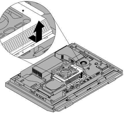
Replacing the microprocessor fan assembly
Attention:
Do not open your computer or attempt any repair before reading and understanding the “Important safety information” in theThinkCentre Safety and Warranty Guidethat came with your computer. To obtain a copy of theThinkCentre Safety and Warranty Guide, go to:
http://www.lenovo.com/support
This section provides instructions on how to replace the microprocessor fan assembly. To replace the microprocessor fan assembly, do the following:
4. Remove the frame stand or lift stand. See “Removing or reinstalling the frame stand” on page 16 or “Removing or reinstalling the lift stand” on page 17.
5. Remove the rear I/O assembly cover. See “Removing or reinstalling the rear I/O assembly cover” on page 19.
6. Remove the VESA frame cover. See “Removing or reinstalling the VESA frame cover” on page 20. 7. Note the routing of the microprocessor fan assembly cable and then disconnect the microprocessor fan
assembly cable from the system board.
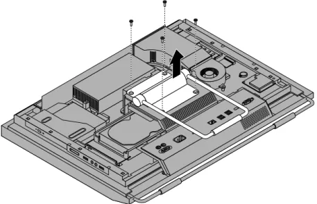
8. Remove the three screws 1 that secure the microprocessor fan assembly and then lift the microprocessor fan assembly off the system board.
Figure 33. Removing the microprocessor fan assembly
9. Position the new microprocessor fan assembly on the system board and align the three screw holes in the new microprocessor fan assembly with those in the system board.
10. Install the three screws to secure the microprocessor fan assembly to the system board.
11. Connect the microprocessor fan assembly cable to the system board. See “System board part and connector locations” on page 12.
12. Reinstall the VESA frame cover and the rear I/O assembly cover. What to do next:
• To work with another piece of hardware, go to the appropriate section.
• To complete the installation or replacement, go to “Completing the parts replacement” on page 52.
Replacing the card reader
Attention:
Do not open your computer or attempt any repair before reading and understanding the “Important safety information” in theThinkCentre Safety and Warranty Guidethat came with your computer. To obtain a copy of theThinkCentre Safety and Warranty Guide, go to:
http://www.lenovo.com/support
This section provides instructions on how to replace the card reader. Note: The card reader is available only in some models.
To replace the card reader, do the following:
1. Remove all media from the drives and turn off all attached devices and the computer. Then, disconnect all power cords from electrical outlets and disconnect all cables that are connected to the computer. 2. Place a soft, clean towel or cloth on the desk or surface. Hold the sides of your computer and gently lay
it down so that the screen is against the surface and the cover is facing up. 3. Remove the computer cover. See “Removing the computer cover” on page 15. 4. Locate the card reader in the computer. See “Component locations” on page 11. 5. Disconnect the USB cable from the card reader.
6. Remove the two screws that secure the card reader and then lift the card reader out of the computer.
Figure 34. Removing the card reader
7. Align the screw holes in the new card reader with those in the computer and then install the two screws to secure the card reader.
Replacing the rear I/O assembly
Attention:
Do not open your computer or attempt any repair before reading and understanding the “Important safety information” in theThinkCentre Safety and Warranty Guidethat came with your computer. To obtain a copy of theThinkCentre Safety and Warranty Guide, go to:
http://www.lenovo.com/support
This section provides instructions on how to replace the rear I/O assembly. To replace the rear I/O assembly, do the following:
1. Remove all media from the drives and turn off all attached devices and the computer. Then, disconnect all power cords from electrical outlets and disconnect all cables that are connected to the computer. 2. Place a soft, clean towel or cloth on the desk or surface. Hold the sides of your computer and gently lay
it down so that the screen is against the surface and the cover is facing up. 3. Remove the computer cover. See “Removing the computer cover” on page 15.
4. Remove the rear I/O assembly cover. See “Removing or reinstalling the rear I/O assembly cover” on page 19.
5. Locate the rear I/O assembly. See “Component locations” on page 11.
6. Remove the four screws 1 that secure the rear I/O assembly and then remove the rear I/O assembly from the computer.
Figure 35. Removing the rear I/O assembly
7. To install the new rear I/O assembly into the computer, connect the new rear I/O assembly to the rear I/O assembly connector on the system board, and then align the four screw holes with those in the computer main bracket. See “System board part and connector locations” on page 12.
8. Install the four screws to secure the rear I/O assembly to the computer main bracket.
9. Reinstall the rear I/O assembly cover. See “Removing or reinstalling the rear I/O assembly cover” on page 19.
What to do next:
• To work with another piece of hardware, go to the appropriate section.
• To complete the installation or replacement, go to “Completing the parts replacement” on page 52.
Replacing the right I/O assembly
Attention:
Do not open your computer or attempt any repair before reading and understanding the “Important safety information” in theThinkCentre Safety and Warranty Guidethat came with your computer. To obtain a copy of theThinkCentre Safety and Warranty Guide, go to:
http://www.lenovo.com/support
This section provides instructions on how to replace the right I/O assembly. To replace the right I/O assembly, do the following:
1. Remove all media from the drives and turn off all attached devices and the computer. Then, disconnect all power cords from electrical outlets and disconnect all cables that are connected to the computer. 2. Place a soft, clean towel or cloth on the desk or surface. Hold the sides of your computer and gently lay
it down so that the screen is against the surface and the cover is facing up. 3. Remove the computer cover. See “Removing the computer cover” on page 15. 4. Locate the right I/O assembly. See “Component locations” on page 11.
5. Disconnect the right I/O assembly cable and the intrusion switch cable from the right I/O assembly. 6. Remove the three screws 1 that secure the right I/O assembly and then remove the right I/O assembly