Jack-up vessel
optimisation
Jack-up vessel optimisation: Improving offshore wind performance through better use of jack-up vessels in the operations and maintenance phase
This study has been prepared by Sally Shenton of Generating Better Limited and Chris Mallett and Mike Frampton of London Offshore Consulting. Assistance was given by Mick Turner of Sinnodyne Ltd and Edward Wood of E W Energy Ltd. This report was commissioned for and by The Crown Estate.
Acknowledgments
Thanks are extended to the following individuals and organisations that have provided assistance and information: The Crown Estate team for their invaluable contributions and support, The Carbon Trust, E.ON and Centrica for their contributions to sections of this report, IBUJOA, DBB Jack up Services, Seajacks UK Ltd, MPI,
Transmission Capital Partners, Offshore Wind Programme Board (Supply Chain and Operations and Maintenance Workstream), Statkraft, SSE, Dong Energy and Vattenfall. Disclaimer
Information used in this report has been assembled from a variety of sources which are not under the direct control of The Crown Estate. The Crown Estate takes no responsibility for the accuracy of information obtained from external and/or public sources, or for the use to which this report may be put.
In identifying suitable vessels for deployment on offshore windfarms for O&M, London Offshore Consulting (LOC) has used vessel specifications that are in the public domain as listed on the owner’s/operator’s publications. LOC accepts no responsibility for the accuracy of this information and no reliance
should be placed on the data unless the specifications have been confirmed by the owners as currently applicable to the vessel and to the proposed operations. Modelling presented in this report has been undertaken to simulate collaboration concepts and should not be relied on in the development of business cases or commercial arrangements. The results of the simulations presented are intended to provide illustrations only of how collaboration may work in practice and identify potential areas of where value could be created or where risks may exist. Using this report
This report has been prepared to assist those with little experience of jack-up vessel use as well as practitioners who are involved in managing strategic and operational aspects of jack-up vessel work in the O&M phase of an offshore windfarm.
1 Executive summary 4
2 Introduction 6
2.1 The operations and maintenance lifecycle 6
2.2 The growing importance of O&M in offshore wind 7 3 The use of jack-up vessels in offshore wind operations
and maintenance 8
3.1 Repairing offshore wind turbines – is a jack-up vessel required? 8
3.2 How are jack-up vessels used? 9
3.3 Planning jack-up vessel operations 9
3.4 Jack-up vessel suitability 12
3.5 Experience to date of using jack-up vessels in O&M 13
3.6 Jack-up vessel costs 13
4 Factors causing delays and opportunities to improve repair times 17
4.1 Impact on cost, revenue and LCOE 17
4.2 Causes of delay 17
4.3 Opportunities to reduce delays to repairs 21 5 Predicting demand and supply of heavy lift jack-up vessels 24 5.1 Estimating the number of heavy lift jack-up vessel operations
required at operational windfarms 24
5.2 Availability of heavy lift jack-up vessels 26
6 Potential collaboration opportunities 28
6.1 Options for collaboration – case studies 28
6.2 Blockers and barriers to collaboration 30
6.3 Opportunities 31
7 Conclusions and recommendations – improving repair times,
minimising repair cost and addressing risk 32 8 Bibliography 34
Annex 1: Definition of jack-up vessels suitable in principle
for O&M projects 35
Annex 2: Potential site hazards that could restrict the sharing
of jack-up vessels 36
Annex 3: Irish Sea Case Study – Supporting Information 38
Contents
1
Executive summary
This study has been commissioned by
The Crown Estate and addresses the use
of jack-up vessels in the operations and
maintenance (O&M) phase of UK offshore
windfarms. It presents experience of the use
of jack-up vessels at operational offshore
windfarms and considers the potential to
improve windfarm performance through better
use of jack-up vessels. The report reviews
the role that increased collaboration between
windfarm owners could play in reducing the
Levelised Cost of Energy (LCOE) and puts this
in context with other potential improvements.
The study focuses on the UK offshore wind
portfolio but considers vessel availability and
demand in the European context and beyond.
More than 500 jack-up vessel interventions at operational offshore windfarms have taken place in the UK to date. There is evidence of long periods of turbine downtime in some cases while repair campaigns are planned and delivered. Production downtime losses while campaigns are planned and implemented have ranged from a few hundred thousand pounds to several million pounds per event.
Jack-up vessel deployment and mobilisation costs can form a substantial proportion of repair bills and can make fast repairs of single turbines challenging to justify in isolation. In addition to supporting work on offshore wind turbines jack-up vessels also have a role to play in the maintenance of offshore substations and associated transmission infrastructure.
Experience gained so far in the use of jack-up vessels in the O&M phase highlights opportunities to contribute to reductions in the LCOE through
• Faster response times to undertake repairs • More efficient project planning
• Reduced charter costs through a more structured, proactive approach in the O&M phase and greater optimisation of geographical campaigns
With the increasing scale of deployment and the geographic clustering of offshore windfarms in the UK and elsewhere, there are now greater opportunities for collaboration which can speed up repair times, reduce repair costs and minimise lost production revenue.
Improved planning and collaborative approaches, aided by improvements in the use of condition-based information, could increase revenues by £52m – £110m per year across currently operational UK offshore windfarms. As larger turbine models are introduced and the size of the operational fleet grows, the benefit of better jack-up vessel use will make an even greater contribution to reducing LCOE.
Uncertainty about long term failure rate trends makes it challenging for owners to make commitments to long term vessel charters. A collective full time jack-up vessel charter may offer benefits if there is a large take-up of club membership and failure rates are relatively high but alternatives exist.
A flexible charter club offers an alternative proactive approach to collaboration, with owners pre-planning for vessel-sharing without engaging a full time shared vessel. This form of flexible jack-up club offers the simplest starting point to improve readiness and facilitate rapid ad-hoc shared vessel charters. This is achieved through: proactive site assessment, contractual readiness, improved communication between windfarm owners, alignment of repair practices/working methods and contracting
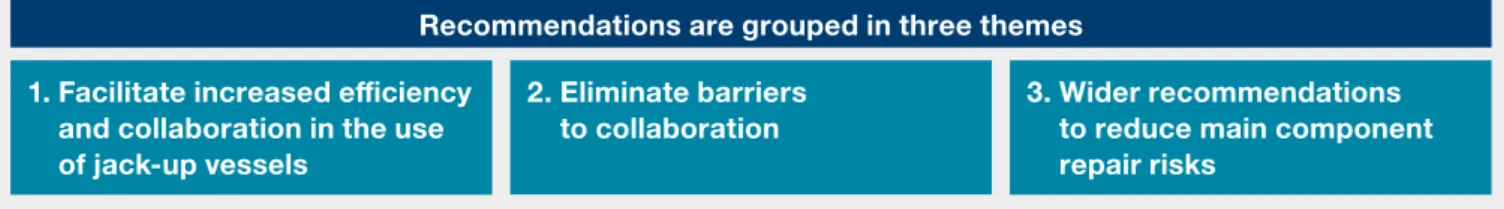
Figure 1: Specific recommendations for progressing this concept are contained in section 7 Recommendations are grouped in three themes
1. Facilitate increased efficiency and collaboration in the use of jack-up vessels
2. Eliminate barriers
to collaboration 3. Wider recommendations to reduce main component repair risks
approaches. This approach avoids owners being required to commit significant budget to charter a vessel that they may not fully require and also enables rapid deployment. This improves the efficiency of jack-up vessel deployment and offers cost savings on mobilisation and usage. A flexible charter club introduces a lower risk, lower cost option to increase benefits to windfarm owners and takes its lead from a successful vessel collaboration seen recently on the east coast of the UK. The use of a ‘club’ based approach extends the concept to ensure heightened readiness with the potential to reduce vessel availability risk and associated production downtime. Some specific recommendations for progressing this concept are at section 7.
A marked reduction in the need to use a jack-up vessel to repair operational wind turbines through increasing in-situ repair capability and improvements in turbine reliability is also key in delivering sustainably high performance. Further development of condition based monitoring and predictive failure modelling will increase proactive repair intervention and extend planning windows for jack-up vessel work resulting in higher levels of wind turbine availability. Realistically, however, there will be a continuing role for jack-up vessels in the maintenance of offshore windfarms and their associated offshore transmission infrastructure. Collaborative approaches have the potential to reduce costs and increase production income and should be considered further.
Until recently, the market for operations and
maintenance (O&M) jack-up vessels was limited
to a small number of users and suppliers. Original
Equipment Manufacturers (OEMs) have been
the predominant user of O&M jack-up vessels
with much use focused on meeting warranty
commitments and guarantees. This landscape
is rapidly changing as more offshore windfarms
move beyond the initial warranty period and
newer strategies emerge for sharing jack-up
vessel risk within more recently agreed warranty
contracts. Windfarm owners and operators
are increasingly taking more responsibility for
delivering arrangements for O&M jack-up vessels
which is leading to an increase in the number of
users and a potentially larger number of individual
jack-up campaigns which are smaller in scope.
Increased collaboration and the sharing of good practice to speed up jack-up vessel deployment now has the potential to improve the way jack-up vessels are used during the O&M phase. With increasing numbers of turbines now installed and clear geographical clusters emerging, this study identifies opportunities for industry-wide collaboration and other potential improvements in the use of jack-up vessels which could speed up repair times, reduce maintenance costs and improve overall levels of electricity production. The number and capability of jack-up vessels has increased over recent years but with corresponding increases in charter costs for larger vessels designed for efficient construction campaigns, there are still relatively few lower-cost O&M-focused jack-up vessels. As a result owners are seeking to optimise the strategic use of jack-up vessels in the O&M phase to address main component failures in an efficient and cost-effective manner.
This study focuses on the post-construction period
with both warranty and post-warranty periods included. The construction and decommissioning phases of the windfarm development lifecycle are not covered by this study.
Simulations are used to illustrate potential benefits based on forecast build out rates to 2020 using a simplified approach and using assumptions based on industry experience. Through the development of models for collaboration, removing barriers and sharing examples of good practice, it is likely that increased collaboration can contribute to reducing the Levelised Cost of Energy (LCOE).
2
Introduction
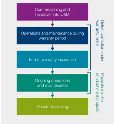
2.1 The operations and maintenance lifecycle The current typical design life of offshore windfarms is between 20 and 25 years. Through this period, routine operation and maintenance tasks will be required to ensure asset performance is optimised. Specific maintenance campaigns will be designed to ensure continued high levels of performance throughout the lifetime of these assets. The lifecycle of an operational windfarm is shown in Figure 2. In the early stages of the asset life, owners will usually enter into contracts with the OEM which will include warranties on the performance of the assets. Initial warranty periods generally span the first two to five years and place responsibility and liability for early-life plant failures with the OEM.
Once the initial warranty period has ended, owners have a range of options for delivering O&M activities which range from extended OEM warranty contracts, use of independent service providers and deliver maintenance with their own teams.
O&M costs are estimated to make up at least a quarter of overall offshore windfarm lifetime costs and O&M could become a £2bn per year industry across the UK offshore wind sector by 2025 (GL Garrad Hassan, 2013). Efficiencies and cost savings in the O&M period represent a strong opportunity to make a material contribution towards industry targets to reduce LCOE (The Crown Estate, 2012).
Figure 2: The O&M lifecycle of an offshore windfarm
Commissioning and handover into O&M
Operations and maintenance during warranty period
End of warranty inspection
Ongoing operations
and maintenance
Decommissioning
Defect corr
ection under
warranty terms
Possible mid-life
refurbishment pr
2.2 The growing importance of O&M in offshore wind
The offshore wind sector in the UK has seen considerable growth since the first Round 1 windfarms were constructed in 2002/3. The Crown Estate has overseen two rounds of offshore windfarm development which has resulted in large scale deployment of offshore wind turbines off the coast of the UK. There are currently 1,239 operational offshore turbines in UK waters with a further 213 under construction (figures correct as at 25 July 2014).1
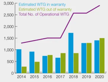
Preparations for extensions to several Round 1 and Round 2 windfarms are ongoing along with the implementation of Round 3, Scottish Territorial Waters and Northern Ireland developments. Depending on development and construction timetables for future planned offshore windfarms there could be more than 3000 turbines operational or under construction by 2020 representing a significant fleet of assets within the UK. The total number of operational turbines to 2020 has been estimated (Figure 3) and this has been used in simulations of jack-up vessel demand later in this report. Estimates are based on one of many possible scenarios and represent a mid-case assessment of potential build out rates, drawing on information published by Renewables UK (Renewable UK, 2013).
0 500 1,000 1,500 2,000 2,500 3,000
2020 2019 2018 2017 2016 2015 2014
Figure 3: Assumed number of operational offshore wind turbines based on mid-case estimates of build-out to 2020
Estimated WTG in warranty Estimated WTG out of warranty Total No. of Operational WTG
1 Operational data as at 25 July 2014. Those sites classed as under construction include: a proportion of Gwynt y Môr and West of Duddon Sands (which are partially operational) and all of Westermost Rough and Humber Gateway which have not yet started generating electricity.
3
The use of jack-up vessels in offshore wind
operations and maintenance
The O&M phase of an offshore windfarm
will invariably require some use of jack-up
vessels to replace main components located
at the top of the turbine tower. Experience
from early operations in the offshore wind
sector points to a range of uses of jack-up
vessels in the O&M phase. In addition to
single turbine repairs, there have been some
large-scale retrofit campaigns to address
type faults thereby reducing the risk of failures
later in life and improving long term yields.
There have also been examples of isolated
single-turbine failures which have resulted
in some period of extended down-time while
a jack-up vessel is sourced.
3.1 Repairing offshore wind turbines – is a jack-up vessel required?
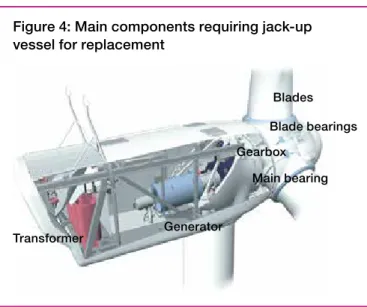
A wide range of maintenance activities is required at offshore windfarms to ensure high availability and resulting commercial benefits. In 2013, The Crown Estate and Scottish Enterprise published A Guide to UK Offshore Wind Operations and Maintenance (GL Garrad Hassan, 2013) which describes the approaches to operating and maintaining offshore windfarms and sets out the various activities required. A key aspect of O&M requiring access to jack-up vessels is responding to defects and faults with main turbine components – blades, gearbox, generator and in-turbine transformer. In an offshore wind turbine these are commonly located at the top of the tower either inside or connected to the nacelle (the only current exception being the turbine transformer which can be located in the tower base on some models).
Although turbines are often supplied on the basis that the main components have a design life of 20+years, experience in smaller, mature onshore turbines has shown that, in reality, failures will occur. Some of the common defects offshore can be repaired in-situ using teams that travel out to the turbine in a normal crew transfer
vessel, using cranes located on the turbine. However, not all repairs can be made this way. Owing to the weight and size of some components there are repairs which require a larger crane or need to be carried out externally to the turbine (Figure 4).
There are also situations which require a replacement of the entire component to be made. Each of these components is heavy and typically cannot be lifted with the crane installed in the turbine. It is necessary to bring a heavy lift jack-up vessel fitted with a crane onto the site to act as a lifting platform. Not all main component failures require the replacement of an entire component and some turbine designs allow main components to be disassembled in-situ and repairs made using parts which can be deployed using standard crew transfer vessels. The degree to which in-situ repairs are possible will vary with turbine type and examples of in-situ repairs are shown in Table 1 (noting that these examples will vary between different turbine designs).
For in-situ repairs it is possible to lift spare parts and tools from a crew transfer vessel using a crane mounted in the nacelle. Given the size and weight of the components, the lifting operation requires planning to ensure high standards of health and safety – this may mean that it can only be
Figure 4: Main components requiring jack-up vessel for replacement
There are examples of extended periods of turbine downtime while repair plans using
jack-up vessels are put into place. In some cases single turbine events have resulted
in over £1m lost production income.
Blades
Main bearing Gearbox
Generator Transformer
Figure 5: Stages in jack-up vessel deployment and typical durations
Mobilisation Loadout Sea transit Positioning on site Elevated operations Demobilise
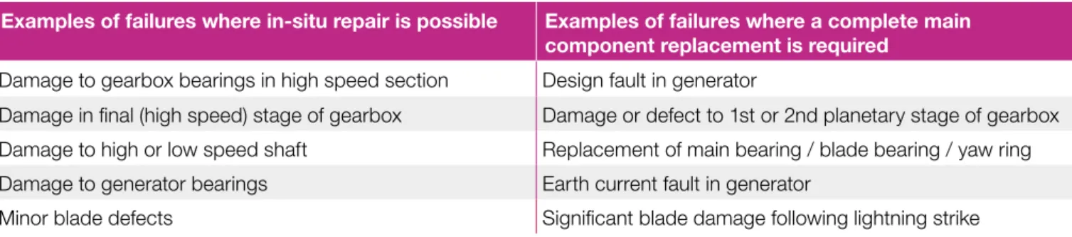
Table 1: Examples of main component failures and associated repair action
Examples of failures where in-situ repair is possible Examples of failures where a complete main component replacement is required
Damage to gearbox bearings in high speed section Design fault in generator
Damage in final (high speed) stage of gearbox Damage or defect to 1st or 2nd planetary stage of gearbox Damage to high or low speed shaft Replacement of main bearing / blade bearing / yaw ring Damage to generator bearings Earth current fault in generator
Minor blade defects Significant blade damage following lightning strike
Early detection of defects, enabled through the use of condition-based monitoring techniques
and inspections, can remove the need to use a heavy lift jack-up vessel if the turbine is
designed to enable in-situ repairs.
carried out during calm seas or low winds. Even with these restrictions the speed of repair is likely to be considerably faster and at significantly lower cost than using a heavy lift jack-up vessel.
There are numerous examples from existing operational sites where in-situ repairs on main components have cost less than undertaking full component replacement using a heavy lift jack-up vessel. Many of these depend on detecting technical issues early through the combined use of condition-based monitoring techniques and inspections in order to avoid more extensive damage to the turbine (See Section 4.3) 3.2 How are jack-up vessels used?
When it is necessary to replace a main component, heavy lift jack-up vessels provide a stable lifting platform and can hold a crane with sufficient reach to replace components in the nacelle. The large deck space on a jack-up vessel can be used to store multiple spare parts and avoid or reduce the need to transit back and forth to collect parts from a port. Once the jack-up vessel is in position, the crane located on the vessel is used to lift the defective component out of the turbine and place the new component into position. Prior to the jack-up vessel arriving on site, work will have been undertaken to prepare the turbine, which may include the disconnection of electrical and control cables, draining of oil and preparations for the safe delivery of the lifting operation. The tasks to prepare the turbine for
main component exchanges are usually carried out using standard windfarm crew transfer vessels.
The stages of jack-up vessel operations carried out in connection with O&M activity on offshore windfarms are shown in Figure 5.
The time taken for lifting operations to exchange components can be a relatively small proportion of the whole process. Operational procedures will be put in place to ensure effective management of health, safety and environmental issues during the work and industry standard guidelines have been developed to aid this (Renewable UK, 2013) (Renewable UK, 2012). These procedures will also include measures to coordinate heavy lift jack-up vessel entry onto site and movements around the site with particular focus on the approach route to each turbine, selection of the position where the vessel will stand and minimising the risk of any collateral damage to subsea cables and the turbine structure. Further details can be found in Annex 2.
3.3 Planning jack-up vessel operations
Windfarm owners have a range of options when planning to replace main components. These are largely driven by the high cost of jack-up vessels in relation to the total cost of the repair. Choices about how and when to deploy a jack-up vessel are driven by the mobilisation cost of the vessel (which may vary depending on the vessel reaction
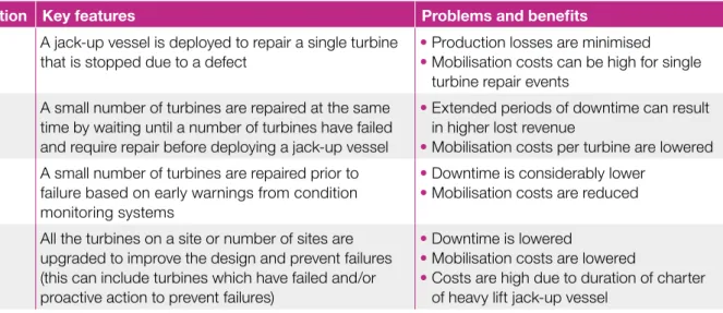
Table 2 : Main component repair strategy options
Type of operation Key features Problems and benefits
Single
turbine repair A jack-up vessel is deployed to repair a single turbine that is stopped due to a defect •• Production losses are minimised Mobilisation costs can be high for single turbine repair events
Reactive
batch repairs A small number of turbines are repaired at the same time by waiting until a number of turbines have failed and require repair before deploying a jack-up vessel
• Extended periods of downtime can result in higher lost revenue
• Mobilisation costs per turbine are lowered
Proactive
batch repairs A small number of turbines are repaired prior to failure based on early warnings from condition monitoring systems
• Downtime is considerably lower
• Mobilisation costs are reduced Serial defect
campaigns All the turbines on a site or number of sites are upgraded to improve the design and prevent failures (this can include turbines which have failed and/or proactive action to prevent failures)
• Downtime is lowered
• Mobilisation costs are lowered
• Costs are high due to duration of charter of heavy lift jack-up vessel
time) balanced against the cost of lost production revenue incurred from any downtime. For single or low numbers of turbines requiring repairs, a fast vessel mobilisation may not always be the most cost-effective action especially where there is a long period of advance warning of a fault through alarms provided by condition monitoring systems.
Main components can be replaced as a single turbine repair, repairs can be grouped together (so-called ‘batch repairs’) or campaigns can be run across the whole site to install an updated design, for example. These scenarios are illustrated in Table 2.
There will be a break-even point between the additional cost of undertaking a fast repair and the additional lost revenue risked by waiting for further turbines to fail before mobilising a jack-up vessel. However, it is often not possible to predict when the next turbine will fail and strategies to wait for a number of defective turbines can be more costly if the average time between failures is considerable. It is difficult to predict the remaining life of main components at present owing to lack of operational experience although predictive tools are being developed and there are already many examples of effective early warnings.
Regardless of the strategy chosen, project planning needs to combine jack-up vessel activity planning with the maintenance tasks required to complete the repair. This is illustrated in Figure 6 and shows the need to coordinate the arrival of spare parts at the load-out port, preparation of the turbine for the removal of the faulty component and the time taken after the jack-up vessel has been used to rebuild and re-commission the turbine so that it can be returned to an operational state. Figure 7 also shows the stages of project planning. The complexity of the planning activity will increase as the number of turbines in any campaign increases. The basic operating specifications for the jack-up vessel in terms of requirements for load capacity, deck space, lifting capacity, services and accommodation can reasonably be finalised once there is a clear definition of the O&M tasks
to be carried out. From this assessment a short list of jack-up vessels can be drawn up; however, the selection of a suitable jack-up vessel cannot be based on this initial assessment alone and a site-specific assessment is required. The site-specific assessment is discussed in detail in section 3.4. Failure to apply the relevant technical expertise to this preliminary assessment can result in the selection of an unsuitable jack-up vessel with consequential delay or increased campaign risk.
Formal planning consent or marine licensing is not required to deploy a jack-up vessel during the O&M phase of an offshore windfarm. However, there may be site specific environmental considerations which require liaison with regulators and their statutory consultees. There may also be requirements to undertake surveys or assessments, but windfarm owners have been working with regulatory bodies to streamline this process and ensure high standards of environmental care while not incurring costly delays to jack-up vessel deployment.
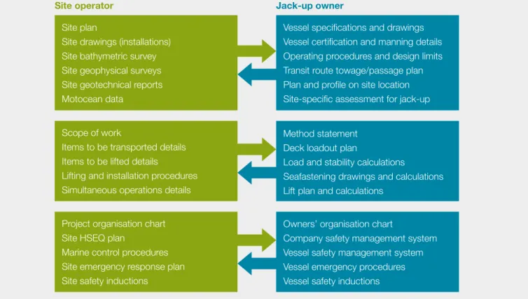
A comprehensive exchange of technical information between the site owner and the jack-up vessel owner is an essential part of project planning. An outline list of the information to be exchanged is illustrated opposite in Figure 7. The availability of this information and the time taken to prepare and distribute it has a direct impact on the project timeline. Efficient planning depends on the availability and quality of the metocean data, site geophysical surveys and the soil investigation reports. Omissions or deficiencies in the quality of this information may not be identified until later in the planning process; this can result in delays caused by the need for clarification, additional data processing or new site surveys. Detailed planning must include a competent assessment of not only the environmental, geophysical and geotechnical conditions existing at the site, but also the layout of fixed structures, subsea pipelines and cables and scour protection materials. For this reason it is essential that all the relevant information has been entered on the site plans.
Figure 6: Interaction between planning, jack-up vessel operations and turbine maintenance tasks
Mobilisation Loadout Sea transit Positioning on site Elevated operations Demobilise
Assess vessel
suitability Contract
negotiation Operational planning
Potential delays due to poor weather or rough sea states
Project planning
Contractor audit and
vessel inspection Technical
information exchange Contract
negotiation Project
consent planningDetailed approvalProject
Spare part delivered
to loadout port Turbine preparation
Lift defective
component out
and replace
Rebuild turbine,
commission
and test
Figure 7: Technical Information Exchange
Site operator Jack-up owner
Site plan
Site drawings (installations) Site bathymetric survey Site geophysical surveys Site geotechnical reports Motocean data
Vessel specifications and drawings Vessel certification and manning details Operating procedures and design limits Transit route towage/passage plan Plan and profile on site location Site-specific assessment for jack-up Scope of work
Items to be transported details Items to be lifted details
Lifting and installation procedures Simultaneous operations details
Method statement Deck loadout plan
Load and stability calculations
Seafastening drawings and calculations Lift plan and calculations
Owners’ organisation chart
Company safety management system Vessel safety management system Vessel emergency procedures Vessel safety inductions Project organisation chart
Site HSEQ plan
Marine control procedures Site emergency response plan Site safety inductions
The wide range of geophysical, geotechnical and environmental differences that exist
between different offshore windfarms and different turbines locations on a single windfarm
means that there is currently no single jack-up vessel in the current market that can work at
every UK turbine location.
The suitability of the jack-up vessel for elevated operations at any location offshore is determined by the site-specific assessment in accordance with the international industry standard contained in ISO-19905-1.
The site-specific assessment evaluates the stability and structural integrity of a jack-up vessel in relation to the environment in which it is to be used. The assessment is a complex analysis which combines detailed information about the jack-up vessel structure with site-specific
geophysical and geotechnical data (from the site survey and soil investigation reports) and the extreme environmental conditions described in metocean reports. Using all of this information it is possible to assess the predicted behaviour of the jack-up vessel and analyse the impact of wind, wave and current loads on it. This can be used to determine whether the vessel can remain safely elevated on location in severe weather conditions.
In cases where the jack-up vessel may not be able to remain safely elevated in extreme storms, it is possible for limits to be set which determine the most severe environmental conditions that it could safely withstand at a specific location. Any forecasts exceeding these limits will constrain operations and may even require the vessel to take shelter before weather fronts are experienced. In practice this can result in lengthy operational delays if weather forecasts are uncertain or where there are only limited windows of acceptable weather.
Parts of the site-specific assessment can be carried out in advance of planning a specific project. However, the detailed nature and characteristics of each turbine location need to be considered before the jack-up vessel capability Delays can be avoided by maintaining a robust set of
information that is easy to transfer to others involved in the repair. Delay in information exchange can also be reduced by arranging non-disclosure agreements, if required, well in advance.
The final stage of planning is a formal review by the site owner/operator, key contractors , jack-up vessel owner and marine warranty surveyor to ensure that all parties agree in detail with the procedures to be adopted. This can be completed within 14 days or less if relevant parties have been involved at an early stage of the planning cycle.
3.4 Jack-up vessel suitability
Certain types of jack-up vessels are more capable of working on particular seabed types, for example soft soils, whereas others are more suitable for deployment on hard rock or boulders. Some jack-up vessels can be modified (although this is likely to incur considerable expense) to make them more suitable for greater water depths and different seabed conditions but it is stressed that there is currently no single jack-up vessel that is capable of accessing every offshore turbine installed or in planning.
Each class of jack-up vessel is subject to a different set of limiting criteria which governs their operations and these limitations can have a significant effect on the feasibility of carrying out O&M projects in a timely and economical manner. The vessel needs to be assessed to understand if it is technically and commercially suitable to undertake each project and the stages in this assessment are shown in Figure 8.
Mobilisation Loadout Sea transit Positioning on site Elevated operations Demobilise
Figure 8: Technical studies required to determine suitability of jack-up vessel for working at an offshore windfarm
Assess vessel
suitability Contract
negotiation Operational planning
Characteristics of sea route and vessel’s size, seaworthiness and sea keeping ability
Only if jacking up for loadout
Cable proximity/damage
risk assessment
Site-specific assessment – ensures vessel has sufficient structural strength & overturning stability in relation to site conditions and soil type at specific location(s) it is to be used
COURTESY OF DBB JACK-UP
Group 3 – multi-purpose self-propelled jack-up vessels which are capable of working in offshore wind and the oil and gas sector.
In groups 1, 2 and 3, ship-shaped vessels have typically higher transit speeds than self-propelled barges.
Group 4 – jack-up vessels which are not fitted with propulsion systems and which are towed by tugs and positioned using anchors and moorings
In all groups, the deployment of jack-ups in very shallow water presents a challenge. Most self-propelled jack-ups require deeper water to operate the propulsion thrusters than non-propelled barges but non-propelled barges must deploy anchors for positioning. The high risk of damage to subsea cables caused by the mooring operations may prevent non-propelled jack-ups from approaching turbines located in very shallow water.
3.6 Jack-up vessel costs
The costs of a jack-up operation are split into mobilisation, charter and demobilisation costs, as shown in Figure 10. The overall cost will be a factor of:
• Site & task specific factors including windfarm location and transit distance4, number of turbines requiring jack-up vessel operations and extent of any ‘’wait on weather’’ time during load-out, transit and on-site operations
• Vessel related factors including vessel size, capability and vessel capital cost/owners target utilisation
• Market related factors including type of charter (spot vs long term), demand within the market and time of year
is confirmed. This is because each location may present a different set of challenges.
The reliability of the site-specific assessment depends upon the accuracy of the data supplied. Any location-specific survey data must be updated regularly as seabed changes can occur over relatively short periods of time. These changes can have an adverse impact on the feasibility of installing and operating the jack-up vessel. 3.5 Experience to date of using jack-up vessels in O&M
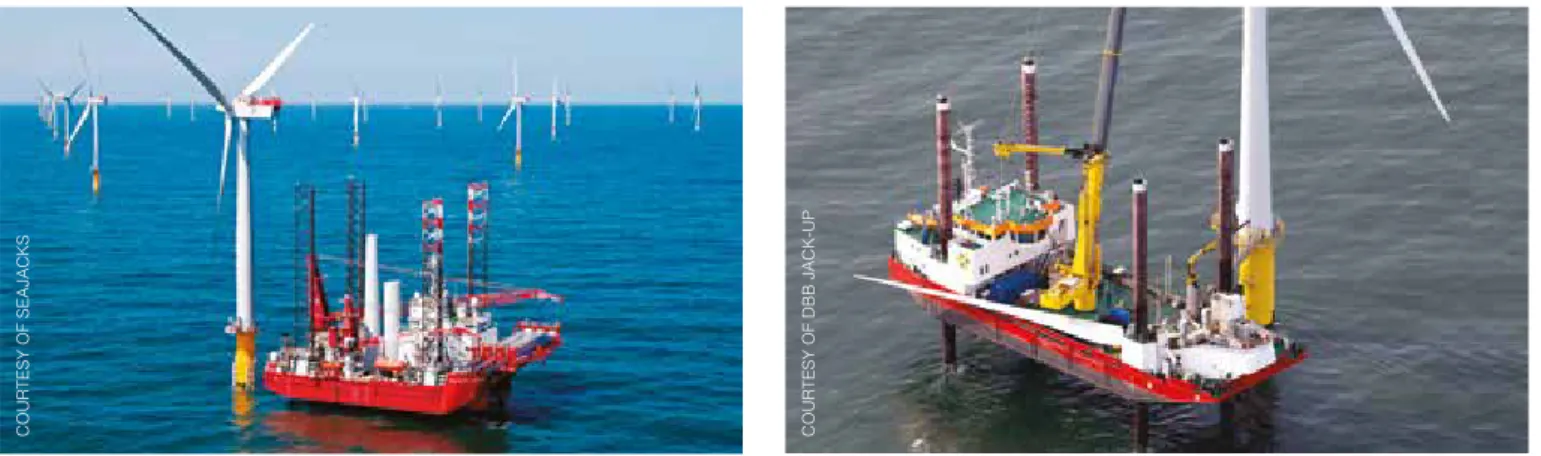
Post-construction vessel operations at UK offshore windfarms have ranged from single turbine repairs to site-wide engineering upgrade programmes. A site-wide variety of vessels have been used and based on this experience, the current fleet available to UK operational offshore windfarms has been collated. Vessels have been grouped2 to illustrate the nature of each vessel’s principal service in the marine renewable energy industry. Vessel information has been provided based on publicly available sources3. Criteria for selecting vessels and further information on vessel groups are given in Annex 1.
Group 1 – versatile and economical self-propelled or propulsion-assisted vessels built or modified specifically for servicing offshore wind turbines during the O&M phase
Group 2 – Self-propelled dynamically positioned self-elevating jack-up vessels specifically designed to transport, lift and install wind turbine generators (WTG) and their foundations during the construction phase, typically attracting higher charter rates than Group 1 because of their larger capacity – these can also be used on O&M tasks
Figure 9: Examples of jack-up vessels used in the O&M phase of offshore windfarms
2 The nominal boundaries of the groups are by no means rigid or absolute as it will be recognised that most of the listed vessels can legitimately be listed in more than one category because they are capable of, or can be modified to suit, a wide range of offshore services in all aspects of the marine industry.
3 The listed maximum operating water depth is a nominal value because the actual limiting depth for each deployment will depend upon the installed leg length, the leg penetration, the minimum safe air gap and the required operating air gap. This can only be defined by the site-specific assessment for each location and the results of the assessment will determine whether installation and operation of the jack-up is feasible and whether any operating constraints or weather restrictions will apply which might affect the efficiency of the operation. The listed load and capacity data has been extracted from the vessel owner’s published information. The data is general in nature and should not be used for project planning without confirmation from the owners because the actual load capacity will depend upon the type of load, the deck layout and the vessel’s floating and elevated stability. The lifting capacity may change depending upon the crane boom configuration and other factors.
Group 1: Jack-ups and leg stabilised vessels particularly suitable for O&M projects Owner/Operator
vessel name Water depth(max) Deck load capacity Crane load capacity Remarks
DBB
WIND 35 m 430 m
2
492 t 30 t @ 30 m Self-propelled and dynamically positioned jack-up barge fitted with a retractable bow thruster to allow operation in very shallow water
DBB
WIND PIONEER 34 m 530 m
2
650 t 232 t @ 19 m Propulsion-assisted and dynamically positioned jack-up barge fitted with 4 retractable thrusters and a mooring system to allow access to shallow water locations. Available Jan 2015
DBB
WIND SERVER 45 m 1000 m
2
1500 t 400 t @ 20 m Self-propelled and dynamically positioned ship-shaped jack-up. Available Aug 2014
A2SEA
SEA POWER 24 m 1020 m
2
2386 t 230 t @ 22 m Self-propelled (non-DP) ship-shaped leg-stabilised vessel uses two anchors to assist positioning Group 2: Windfarm Installation Vessels (WIV) that could also be used during O&M
Owner/Operator
vessel name Water depth(max) Deck load capacity Crane load capacity Remarks
MPI
RESOLUTION 35 m 3200 m
2
4875 t 600 t @25 m World’s first ship-shaped wind turbine installation vessel
MPI
ADVENTURE 40 m 3600 m
2
6415 t 1000 t @ 25 m Ship-shaped enhanced WIV vessel based on RESOLUTION
MPI
DISCOVERY 40 m 3200 m
2
6541 t 1000 t @ 25 m Ship-shaped enhanced WIV vessel based on RESOLUTION
A2SEA
SEA INSTALLER 60 m 3350 m
2
5000 t 800 t @ 24 m GustoMSC 9000G class ship-shaped jack-up vessel
A2SEA
SEA CHALLENGER 60 m 3350 m
2
5000 t 900 t @ 24 m GustoMSC 9000G class ship-shaped jack-up (available 2014)
Van Oord
AEOLUS – 3300 m
2
6500 t 900 t @ 30 m GustoMSC 9000G class ship-shaped vesselConstruction in progress 2014
RWE Offshore Logistics
FRIEDRICH 45 m 4500 t 1000 t @ 25 m Construction vessel purpose-built self-propelled jack-up barge for offshore wind
RWE Offshore Logistics
VICTOR MATHIAS 45 m 4500 t 1000 t @ 25 m Construction vessel purpose-built self-propelled jack-up barge for offshore wind
Bard Engineering
WINDLIFT -1 45 m 2000m
2
2000 t 500 t @ 31 m Construction vessel purpose-built self-propelled jack-up barge for offshore wind
Improving knowledge of the use of
jack-up vessels through training and
experience gained during prior jack-up
vessel campaigns can reduce the
planning and information exchange
timeline by up to 70%.
Group 3: Self-propelled multi-role heavy lift jack-ups
Group 4: Non-propelled jack-up barges Owner/Operator
vessel name Water depth(max) Nominal load capacity Crane load capacity Remarks
Swire Blue Ocean
PACIFIC ORCA 75 m 4300 m
2
8400 t 1200 t @ 31 m Self-propelled DP2 ship-shaped jack-up fitted with helideck
Swire Blue Ocean
PACIFIC OSPREY 75 m 4300 m
2
8400 t 1200 t @ 31 m Self-propelled DP2 ship-shaped jack-up fitted with helideck
Hochtief/GeoSea
INNOVATION 50 m 8000 t 1500 t @ 31 m Self-propelled DP2 ship-shaped jack-up fitted with helideck
Fred Olsen Windcarrier
BRAVE TERN 45 m 3200 m
2
600 t 800 t @ 24 m Self-propelled DP2 ship-shaped jack-up fitted with helideck
Fred Olsen Windcarrier
BOLD TERN 45 m 3200 m
2
600 t 800 t @ 24 m Self-propelled DP2 ship-shaped jack-up fitted with helideck
Gulf Marine Services
ENDEAVOUR 65 m 1035 m
2
1600 t 300 t @ 11 m Self-propelled DP2 jack-up barge fitted with a blade rack
Seajacks
ZARATAN 55 m 2000 m
2
3607 t 800 t @ 24 m Self-propelled DP2 jack-up barge fitted with helideck
Workfox
SEAFOX 5 65 m 6500 t 1200 t @ 25 m Self-propelled DP2 jack-up barge fitted with helideck
Seajacks
KRAKEN 41 m 900 m
2
1436 t 300 t @ 16 m Self-propelled DP2 jack-up barge fitted with helideck
Seajacks
LEVIATHON 41 m 900 m
2
1666 t 400 t @ 18 m Self-propelled DP2 jack-up barge fitted with a blade rack
Seajacks
HYDRA 41 m 900 m
2
1666 t 400 t @ 18 m Self-propelled DP2 jack-up barge. Optional helicopter deck or blade rack
Hochtief
THOR 50 m 1850 m
2
2700 t 500 t @ 24 m Self-propelled DP1 jack-up barge fitted with helideck
Hochtief
VIDOR 50 m 3100 m
2
6500 t 1200 t @ 28 m Self-propelled DP2 jack-up barge fitted with helideck
Geosea (DEME Group)
NEPTUNE 40 m 1600 m
2
2500 t 600 t @ 26 m Self-propelled DP2 jack-up barge
Geosea (DEME Group)
GOLIATH 40 m 1080 m
2
1400 t 400 t @ 15 m Propulsion assisted DP2 jack-up barge towed by tug in transit
Owner/Operator
vessel name Water depth(max) Nominal load capacity Crane load capacity Remarks
Jack-Up Barge BV
JB-114 40 m 1000 m
2
1250 t 300 T @ 18 m GustoMSC SEA2000 classJack-up barge
Jack-Up Barge BV
JB-115 40 m 1000 m
2
1250 t 300 T @ 18 m GustoMSC SEA2000 class Jack-up barge
Jack-Up Barge BV
JB-117 45 m 2500 m
2
2250 t 1000 t @ 22 m GustoMSC SEA2000 class Jack-up bargeDP propulsion units optional
Jack-Up Barge BV
JB-118 45 m 2500 m
2
2250 t 1000 t @ 22 m GustoMSC SEA2000 class Jack-up bargeDP propulsion units optional
Jack-Up Barge BV
JB-119 35 m 900 t 300 t @ 15 m Jack-up barge
A2SEA
SEAWORKER 40 m 750 m
2
1100 t 308 t @ 22 m GustoMSC SEA2000 class Jack-up barge
A2SEA
SEAJACK 30 m 2500 m
2
Charter costs for jack-up vessels for use in O&M typically range from £45k to over £100k per day (Dalgic, 2013). Longer-term charter agreements will typically attract a lower charter rate whereas unplanned short term tasks will see higher rates based on conditions in the spot-market at the time of negotiation. Market conditions at the time of the charter can greatly affect costs, leading to potential long term uncertainty. Studies to model jack-up vessel costs suggest that there can be up to 40% difference in costs between a long-term agreed charter and rates on the spot market. This is accentuated during periods of high demand for jack-up vessels and can also vary seasonally. Costs of heavy lift jack-up vessels during the O&M period, therefore, represent a large risk unless contractual rates can be locked in through long term arrangements (Hagen, 2013), (Dalgic, 2013) or by other means.
There are examples of some jack-up vessel owners offering fixed cost jack-up operations in other parts of Europe although this is not currently widespread. As cluster sizes grow and if sea bed conditions allow, this may become a more common, alternative form of contracting in the future.
Figure 10: Cost breakdown for heavy life jack-up vessel usage
Mobilisation Loadout Sea transit Positioning on the sea Elevated operations Demobilise
Mobilisation costs Charter costs Demobilisation costs
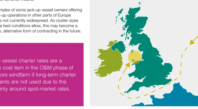
Figure 11: Transit route from North Sea to Irish Sea – three to eight days plus up to several weeks of potential weather delays
The overall cost of deploying a jack-up vessel
includes fuel, port fees, sea fastenings and any expert
advice required for site-specific assessment. The windfarm location can impact on the cost
and availability of the jack-up. For example, longer transit times to the west coast of the UK could either result in potentially higher mobilisation fees or the deployment of a jack-up not being considered feasible at all. There is also increased risk of weather-related delay during transit.
Jack-up vessel charter rates are a
high-risk cost item in the O&M phase of
an offshore windfarm if long-term charter
agreements are not used due to the
uncertainty around spot-market rates.
4 While charter agreements often start at the load-out port, the distance that a barge needs to travel will be reflected in the charter rate and/or mobilisation charge. In practice this is subject to negotiation although jack-up owners will seek to engage with other potential users in an area to try and establish further work for the barge if large transit distances are involved which can reduce mobilisation costs.
Deployment costs to the West Coast of the UK are higher and weather risk is greater –
this may prevent a jack-up vessel being deployed for single turbine repair tasks.
4
Factors causing delays and opportunities
to improve repair times
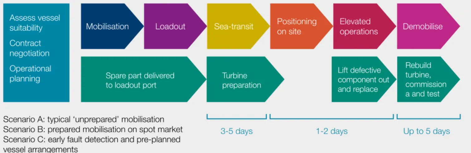
the potential value from better use of jack-up vessels for main component repairs. Value is estimated for three different scenarios, detailed in Figure 12 using standard project requirements for planning a jack-up vessel intervention.
Calculations of the typical value of lost production per turbine downtime event under each scenario are shown in Table 3.
There are isolated examples within the industry of single turbine events resulting in turbine downtime of over a year, sometimes approaching 18 months. In these individual cases the value of this lost production revenue could be as high as £2.5m per event. There are also more isolated examples of very rapid repairs being undertaken, utilising condition-based monitoring information and proactive charter arrangements but currently these are far from being the norm.
4.2 Causes of delay
In order to deliver high levels of electricity production, owners seek to minimise turbine downtime by ensuring any repairs are carried out quickly. Delays to heavy lift jack-up vessel repairs can arise from:
• waiting for a suitable vessel to become available to undertake the repair
• time taken to undertake site surveys and any environmental approvals
• time to undertake procurement activity and negotiate contracts, undertake planning and complete site-specific assessments
• transit times to the operational site and weather-related delays
• lead time on spare parts • poor project execution
The value of lost revenue due to a turbine that
is stopped with a main component fault will
depend on the size of the turbine, the capacity
factor of the windfarm and the incentive regime
under which the windfarm operates. There are
many different factors which result in repair
delays and experience from early repair projects
has demonstrated that improvements in repair
planning can deliver value to owners. It is also
possible to avoid or limit losses caused by
turbine downtime if faults can be identified early
and turbines can safely continue to operate often
with careful monitoring whilst a repair is planned.
4.1 Impact on cost, revenue and LCOE
Experience of current operational offshore windfarms indicates that capacity factors typically range between 34% and 47% with later Round 2 projects at the higher end of this range. Operational windfarms and those currently under construction qualify for Renewable Obligation Certificates (ROCs) of between 1 and 2 ROCs/MW depending on when the windfarm was commissioned and also earn income from selling the power they generate.
The value of long-term turbine downtime has been estimated using capacity factors that reflect the fleet of offshore windfarms in operations and under construction. Typical market rates for electricity and Renewable Obligation Certificates have been used to demonstrate
Figure 12: Overview of planning requirements and potential for delays depending on repair scenario utilised
Mobilisation Loadout Sea-transit Positioning on site Elevated operations Demobilise
3-5 days 1-2 days Up to 5 days
Assess vessel
suitability Contract
negotiation Operational
planning Spare part delivered
to loadout port Turbine preparation
Lift defective
component out
and replace
Rebuild turbine,
commission
a and test Scenario A: typical ‘unprepared’ mobilisation
Scenario B: prepared mobilisation on spot market Scenario C: early fault detection and pre-planned vessel arrangements
The presence or emergence of on-site hazards could restrict the number of suitable jack-up vessels that can work on a site; understanding and tracking such hazards is important and will impact on the potential for any future jack-up vessel clubs or other forms of collaboration. Further information about on-site hazards can be found in Annex 2.
The lack of up-to-date survey information, especially on a site with significant hazards or where frequent changes in water depth are likely, has been a cause of delay on some projects and sites located on shallow sand banks present a particular challenge.
As previously described in Section 3.3, there may be site specific environmental considerations which require liaison with regulators and their statutory consultees. This liaison, along with any requirements to undertake
Waiting time for a suitable vessel
The principal factor causing delays to the completion of early major repairs and/or replacements in the sector has been the higher than anticipated requirement for intervention coupled with the lack of available jack-up vessels capable of carrying out the required tasks. Those vessels capable of carrying out the replacement of turbine components were already engaged in the construction of new offshore windfarms. The distance between windfarms in construction and operating created a situation where the vessels engaged in construction could not easily be released under short-term spot charter agreements to carry out repairs to individual turbines.
Site specific constraints limit the use of particular vessels and can lead to extended waiting periods until a suitable vessel becomes available. Experience to date has highlighted particular problems with very shallow locations and turbine sites with challenging sea-bed conditions, both of which have seen delays identifying and securing a suitable jack-up vessel during the O&M phase. However, notwithstanding the variation in site conditions, performance of the jack-ups listed in this report to date has demonstrated that most will be capable of servicing the great majority of turbines already installed.
Surveys and environmental approvals
The seabed hazards identified during site investigation campaigns carried out before construction continue to present a challenge for the deployment of jack-up vessels for O&M projects. These hazards result in jack-up vessel installation problems caused by:
• seabed slope, sand waves, scour pits, local holes and depressions
• settlement or sliding
• punch-through and soil bearing failure • shallow gas and unexploded ordnance • seabed obstructions such as rocks, boulders,
wrecks, debris
5 Based on typical revenue expectations and production-weighted average capacity factors of 39% (currently operational) and 44% (late Round 2 developments onwards) and assuming a typical turbine capacity of 3.6MW for Round 1/Round 2 and 6MW for Remaining Round 2 / Round 3 / Scottish Territorial Waters / Northern Ireland
6 In this scenario the only downtime experience is while the turbine is stripped down and prepared for the replacement of a main component, the time taken to undertake lifting operations and then to rebuild and recommission the wind turbine
Table 3: Estimated Value of Lost Production arising from single Turbine Downtime event
Scenario Value of lost production (£)5
Round 1/Round 2 Future development A: ‘unprepared’
Six month wait for jack-up vessel while turbine is not producing power £885k £1.7m B: ‘spot market – prepared’
Three month wait for jack-up vessel while turbine is not producing power £443k £867k C: ‘fault detection – pre-prepared’
Condition monitoring predicts defect before failure and jack-up vessel
arrangements in place to ensure no downtime during jack-up vessel mobilisation6 £53k £100k
0 20 40 60 80 100
Event realization Character agreement process Preparation site demonstration Vessel mobilization Marine repair operation Lost time power production
Days 5
50
90
90 93
93
+88
Figure 13: Experience of planning jack-up vessel operations – duration of pre-operational stages (reproduced with permission of DBB Jack-up Services Ltd)
jack-up vessel, or another jack-up vessel of the same design, can be applied to the proposed turbine locations that are to be visited during the O&M project. Production of the site-specific assessment can also be expedited in cases where the contractor performing the analysis has completed previous similar assessments so that the vessel-specific data and the FE model are ready and available.
Geographical location, clustering and impacts on transit times
Where offshore windfarms are clustered, there is greater potential to take advantage of a jack-up vessel that finishes working on an adjacent site. There are large clusters of wind turbines in the Wash, around the Thames Estuary and in the Irish Sea area which can take advantage of this increasing aggregation. Figure 14 shows a number of wind farm clusters which may be able to optimise jack-up vessel usage through collaboration.
Selection of a vessel that is located in the North Sea for an O&M project in the Irish Sea will involve transit time and could incur considerable delay in mobilisation. A selection of typical transit routes and times from the North Sea to offshore windfarms located in the Irish Sea is shown in Table 4 and excludes weather delays. This information will be used as part of the case studies in Section 6.3. Weather conditions through the western part of the English Channel and around Land’s End frequently exceed the prescribed limits for transit for most loaded jack-up vessels. Weather delays of seven days would not be unusual on a coast to coast transit at any time of the year and delays of several weeks can be expected during the winter months.
Weather delays during on-site operations
Jack-up vessels not capable of withstanding extreme storm conditions on site will not be able to remain environmental surveys or assessments, may result in
repair delays.
Time taken in negotiation, planning and site-specific assessments
Between two and six months is a typical period for planning once a potentially suitable vessel has been identified and there are examples of longer waiting times in some circumstances. This is been confirmed in a recent study by a jack-up vessel operator (MAKE, 2014), which reported 88 days lead time to prepare a selected vessel to undertake a project. The largest amount of time taken was in the planning phase and in preparing site documentation, as indicated in Figure 13.
In many early O&M up vessel operations, jack-up vessels without prior site specific experience were employed. Consequently, the poor quality of planning for some early O&M projects led to delays caused by difficulties that had not been foreseen. In recent years, this has been rectified by the windfarm operators, turbine suppliers and jack-up vessel owners/operators. The efficiency of the O&M process has rapidly improved as a result of:
• publication of a technical guidance document through RUK for the marine renewable industry
• provision of jack-up vessel training seminars
• development of competent O&M planning procedures The provision of a jack-up vessel site-specific assessment may involve more than one outsourced service and can require a comprehensive review of the jack-up vessel structural drawings and specifications and the production of a finite element (FE) model. This process can take in excess of 30 days to complete and longer delays should be expected if the outsourced services have not been secured in good time.
Delay can be avoided in circumstances where the results of a previous site-specific assessment for the same
From North Sea To Irish Sea Approx. distance nautical miles Approximate MINIMUM transit time with zero weather delaySelf-propelled ships: 10 knots barges: 6 knotsSelf-propelled Towed barges: 5 knots
Esbjerg, DK Robin Rigg 965 4.0 days 6.7 days 8.0 days
Teesside, UK Mostyn 830 3.5 days 5.8 days 6.9 days
Ijmuiden, NL Mostyn 710 3.0 days 4.9 days 5.9 days
Gt. Yarmouth UK Robin Rigg 695 2.9 days 4.8 days 5.8 days
Table 4: A selection of typical transit times to west coast windfarms EXCLUDING weather delays
Grouping geographically close jack-up vessel operations will reduce the repair costs as
mobilisation costs are shared by a larger number of operators.
Figure 14: Offshore wind map – potential clusters
Operational wind farms Construction wind farms Consented wind farms In planning wind farms Pre planning wind farms Wind farm areas of search Territorial Waters Limit UK Continental Shelf United Kingdom Rest of Europe
km 80
There are good examples of repairs being undertaken quickly and efficiently during the O&M phase. It is important to learn lessons from these successful projects in order to minimise lost production revenue and add value throughout the O&M lifecycle.
Other opportunities to reduce delays in carrying out repairs are discussed below and include:
• use of condition-based monitoring and inspection to provide extended warning of future failure
• windfarm maintenance contract terms, conditions and incentives
• heavy lift jack-up vessel sourcing strategy including collaboration
Use of condition-based monitoring
Use of condition-based information will result in a greater proportion of repairs being undertaken proactively and gains time when repairs can be planned whilst the affected turbine is still operational. This opens up greater possibilities of developing O&M task pipelines which has the potential to reduce LCOE.
Condition-based monitoring and inspection techniques include vibration monitoring and analysis, oil debris analysis, temperature/pressure measurement (usually through the SCADA system), thermal imagery, partial discharge testing and specialise inspections (for example endoscope inspection of gearboxes). Such techniques can play an important role in helping to identify faults early, allowing, in some cases, in-situ repair thus preventing more widespread damage which may require replacement of a main component. This has been successfully used at early operational offshore windfarm sites and can significantly reduce production downtime. Maintenance regimes can also be adjusted to extend the time to failure, this might include grease purging at regular intervals to remove hard damage causing materials or increasing the capacity of in-line oil-filtration systems.
Early fault identification also provides a longer time window to source and plan for jack-up vessel deployment where in-situ repair is not possible. There is evidence that use of more advanced condition-based monitoring can detect faults between three and nine months prior to a downtime failure event occurring.
elevated during periods of bad weather due to constraints introduced as part of the site-specific assessment (described in Section 3.4). These jack-up vessels must be moved to a safe area or place of shelter prior to the onset of severe weather. This requirement can have a considerable impact on O&M projects in terms of delay, particularly in the winter months.
Similarly, jack-up vessels incapable of remaining elevated on site in extreme storms cannot be deployed for O&M in exposed offshore areas where deep leg penetration into the seabed is anticipated. This is because the time required for extraction of deeply penetrated legs cannot be accurately predicted. Consequently, any significant delay in removing the jack-up vessel from site could result in exposure to weather conditions which exceed safe limits before the move to shelter can be completed.
Offshore operations will inevitably incur weather downtime and other unpredictable delays which will accumulate throughout the progress of any O&M campaign. Even work sensibly planned for execution during the benign summer weather season may not be completed as winter approaches. The consequence of this would be that operators of windfarms scheduled for attendance later in the sequence might suffer significantly greater delays than were experienced by the operators of the first windfarm to be visited. This risk would need to be addressed if vessels are being used as part of a collaboration agreement.
Lead time on spare parts
Figure 12 highlights the need to coordinate the turbine maintenance plan with jack-up vessel deployment planning. It is essential that the spare parts required are available in time at the chosen load-out port. There have been examples of owners missing the opportunity to utilise a jack-up vessel because spare parts were not available. This is being addressed by owners through contractual arrangements with suppliers.
4.3 Opportunities to reduce delays to repairs There are generally two ways that jack-up vessels are used to repair offshore turbines – through a reactive repair in response to a sudden failure or as a proactive tasks using condition-based monitoring information or in response to learning in relation to engineering/design issues.
Number of turbines which could be stopped for 12 months and still meet 95% contractual availability guarantee given an assumed “background” contractual availability
“Background” availability (contractual availability excluding main component downtime)
96% 97% 98%
50 turbine site 0 1 2
100 turbine site 1 2 4
150 turbine site 1 3 6
200 turbine site 2 4 8
Table 5: Illustrated impact on long term turbine downtime (in event of main component faults) from availability guarantee-based warranty contracts
Vessel sourcing strategies and collaboration
As owners increasingly take on responsibility for jack-up vessel arrangements, they are beginning to enter into framework agreements with jack-up vessel suppliers to pre-arrange contractual terms and conditions and build effective working relationships. There is also early evidence of owners collaborating with one another and supporting case studies are presented later in this report.
Collaboration offers the potential to deploy jack-up vessels more quickly and reduce charter costs. There are clear drivers to take advantage of clusters and use this to reduce mobilisation costs and address risks from the geographic location of some offshore windfarms, as shown in Table 6. Collaboration has proven to be successful in other industries and three examples are given opposite which illustrate different established methods of collaboration from the oil and gas and telecoms sectors.
The process of developing collaborative working arrangements can be complex and time consuming in the early stages and must provide attractive working practices which deliver value to potential members. The considerations for any ‘club’ arrangement are: • how to levy charges to cover management and
administration
• how to manage the liabilities of its members • how to ensure the total cost of service is calculated
for each member
• setting and meeting performance standards • ensuring priorities are clearly set out and are seen
as ‘fair’ by members
• clearly identifying the value of membership
Definite costs incurred through any upfront charges for collaboration (such as club management fees and charter commitments) must be balanced against the increased revenue earning potential from reduced jack-up vessel deployment times, potential cost savings and potential costs associated with improvements to condition monitoring equipment.
Long term jack-up vessel charters and investing up-front in site-specific assessments are difficult to justify financially on an individual site alone, owing to the relatively high costs involved and the relatively low expected number of failures. However, if these costs can be shared among a larger number of club members then they become cost-effective strategies as illustrated in the case studies later in Section 6.3.
Key influences on repair risk, also the feasibility and cost-effectiveness of any collaborative approach, are the likely supply and demand for jack-up vessels (short and long term) (discussed in Section 5).
Predictive failure modelling enables a proactive replacement strategy for main components which are close to the end of their useful life – this could add value to repair campaigns by using vessels more efficiently. Although there are pilot projects underway, the development of ‘remaining life’ models is still in its infancy in the wind industry.
Windfarm maintenance contract terms, conditions and incentives
In the initial years of the life of an offshore windfarm, it is usual to operate under some form of warranty provided by the original equipment manufacturer, usually with guaranteed performance on an availability or yield basis. Availability-based contracts have been the most commonly used and typically include a number of “permissible events” which are excluded from the guarantee – for offshore wind, access issues, weather delays and sometimes jack-up availability can be excluded resulting in a “contractual availability” calculation upon which the guarantee is based. The availability guarantee is most commonly set at 95% (based on the contractually defined availability).
As offshore windfarms have increased in size and the reliability of smaller components has improved, availability guarantees (defined as an average across the site) can be met even when a number of turbines are stopped for long periods due to main component failures. In early years post commissioning, wind farm performance generally improves. This means there are effectively more hours available for O&M teams to manage breakdowns whilst still achieving a fixed availability guarantee; Table 5 helps illustrate this. Availability guarantee mechanisms are not always an effective driver for the warranty provider to repair defective turbines quickly, especially where jack-up vessel mobilisation costs are relatively high and there is a relatively small number of affected turbines. As the warranty provider is not exposed to the production losses felt by the owner there can arise situations where repair objectives are not aligned.
Some owners are starting to take on responsibility for providing jack-up vessels to warranty providers during the warranty period. It is increasingly common for windfarm owners to be responsible for sourcing jack-up vessels after the warranty period expires even when ongoing maintenance services are provided by the turbine manufacturer.
To attempt to align repair objectives more closely, some turbine manufacturers are now offering maintenance contracts without availability guarantees. Instead, they will provide a guarantee of the output that a windfarm will produce – expressed in terms of the percentage energy yield from the available wind resource. Due to difficulties in measuring yield-based availability and the exclusions applied within guarantees, some operators are focussing on other measures to ensure improved availability. This might include compensation mechanisms based on target turbine down hours for planned service and incentives on extending Mean Time Between Failures and reduced Mean Time To Repair.