A New Controlling Technique for Elimination Lower Order Harmonics In
A Three Phase PV Inverter System
Allam Veeranjaneyulu1, Y.Raja Babu2
1PG Scholar, Pydah College of Engineering, Kakinada, AP, India. 2Assistant Professor, Pydah College of Engineering, Kakinada, AP, India.
Abstract—In this paper, a new controlling technique for elimination lower order harmonics in a three phase PV inverter system topology consisting of a boost section, a low-voltage three-phase inverter with an inductive filter, and a step-up transformer has been proposed. This topology will reduce any lower order harmonics due to high-frequency pulse width modulation operation. However, the non-ideal factors in the system contribute to a important amount of lower order harmonics in the grid current. A new propose of inverter current control mitigates lower order harmonics is presented three phase PV inverter system. A new controller has designed and presented for the lower order harmonic compensation. In addition to that a proportional-resonant-integral (PRI) regulator has been designed. This paper includes an analysis to intend the value of the gain in the proportional controller to achieve an adequate level of harmonic compensation. This PRI controller eliminates the dc element in the control system and introduces even harmonics in the grid current in this topology. The dynamics of the system due to the communication between the PRI controller and the adaptive compensation scheme is also analyzed. The proposed system has constructed in MATLAB/SIMULINK software and the results have been shown.
Index Terms—Adaptive filters, harmonic distortion, inverters, solar energy, three phase system.
I. INTRODUCTION
Many distributed generation (DG) systems making use of the renewable energy sources are being designed and connected to a grid. In this paper, one such DG system with solar energy as the source is considered. The topology of the solar inverter system is simple. It consists of the following three power circuit stages: 1) A boost converter stage to perform maximum power point tracking (MPPT);
2) A low-voltage single-phase H-bridge inverter;
3) An inductive filter and a step-up transformer for interfacing with the grid.
Fig. 1 shows the power circuit topology considered. This topology has been chosen due to the following advantages: The switches are all rated for low voltage which reduces the cost and lesser component count in the system improves the overall reliability. This topology will be a good choice for low-rated PV inverters of rating less than a kilowatt. The disadvantage would be the relatively larger size of the interface transformer compared to topologies with a high-frequency link transformer. The system shown in Fig. 1 will not have any lower order harmonics in the ideal case. However, the following factors result in lower order harmonics in the system [1,2]:
The distorted magnetizing current drawn by the transformer due to the nonlinearity in the B–H curve of the transformer core, the dead time introduced between switching of devices of the same leg, on-state voltage drops on the switches, and the distortion in the grid voltage itself. There can be a dc insertion into the transformer primary due to a number of factors. These can be the varying power reference from a fast MPPT block from which the ac current reference is generated, the offsets in the sensors, and A/D conversion block in the digital controller. This dc injection would result in even harmonics being drawn from the grid, again contributing to a lower power quality.
There has been considerable research work done in the area of harmonic elimination using specialized control. In [15]–[22], multi-resonant controller-based methods are used for selective harmonic elimination. The advantage of these methods is the simplicity in implementation of the resonant blocks. However, discretization and variations in grid frequency affect the performance of these controllers and making them frequency adaptive increases overall complexity. Also, as mentioned in [19], [21], and [22], the phase margin of the system becomes small with multi-resonant controllers and additional compensation is required for acceptable operation. The study in [23]–[25] considers the use of repetitive controller-based harmonic elimination which involves complicated analysis and design. As mentioned in [26], the performance of the repetitive controller is very sensitive to frequency variations and needs structural change for better performance, which might affect the stability In, adaptive filter-based controllers are considered for harmonic compensation. The study in [27] uses an adaptive filter to estimate a harmonic and then adds it to the main current reference. Then, a multi-resonant block is used to ensure zero steady-state error for that particular harmonic reference.
Thus, the study in [27] uses both adaptive and multi-resonant schemes increasing overall complexity. Similar approaches are found in [28] and [29] which add the harmonic current reference estimated using adaptive filters and use a hysteresis controller for the reference tracking. Usage of a hysteresis controller makes it difficult to quantify the effectiveness of this scheme. The study in [30] uses an adaptive filter-based method for dead-time compensation in rotating reference frame, which is not suitable in single-phase systems.
The method proposed in [31] requires an inverse transfer function of the system and is proposed for grid-connected topology assuming the connection to be purely inductive. The advantage of the adaptive filter-based method is the inherent frequency adaptability which would result in same amount of harmonic compensation even when there are shifts in grid frequency. The implementation of adaptive filters is simple. Thus, in this paper, an adaptive filter-based method is proposed. This method estimates a particular harmonic in the grid current using a least-mean-square (LMS) adaptive filter and generates a harmonic voltage reference using a proportional controller. This voltage reference is added with appropriate polarity to the fundamental voltage reference to attenuate that particular harmonic.
This paper includes an analysis to design the value of the gain in the proportional controller to achieve an adequate level of harmonic compensation. The effect of this scheme on overall system dynamics is also analyzed. This method is simple for implementation and hence it can be implemented in a low-end digital controller. The presence of dc in the inverter terminal voltage results in a dc current flow into the transformer primary. This dc current results in drawing of even harmonics from the grid. If the main controller used is a PR controller, any dc offset in a control loop will propagate through the system and the inverter terminal voltage will have a nonzero average value. Thus, in this paper, a modification to the conventional PR controller scheme is proposed.
Fig. 1 Power circuit topology of the 3− φPV system for a low-voltage inverter
An integral block is used along with the PR controller to ensure that there is no dc in the output current of the inverter. This would automatically eliminate the even harmonics. This scheme is termed as proportional-resonant-integral (PRI) control and the design of the PRI controller parameters is provided. The complete scheme is verified by using simulation and the results show a good correspondence with the analysis.
II. LOWER ORDER HARMONICS AND FUNDAMENTAL CURRENT CONTROL
A. Lower Order Harmonics
1) Odd Harmonics: The dominant causes for the lower
order odd harmonics are the distorted magnetizing current drawn by the transformer, the inverter dead time, and the semiconductor device voltage drops. Other factors are the distortion in the grid voltage itself and the voltage ripple in the dc bus. The magnetizing current drawn by the transformer contains lower order harmonics due to the nonlinear characteristics of the B– H curve of the core.
The exact amplitude of the harmonics drawn can be obtained theoretically if the B–H curve of the transformer is known. The phase angle of the harmonics due to the magnetizing current will depend on the power factor of operation of the system. As the operation will be at unity power factor (UPF), the current injected to the grid will be in phase with the grid voltage. However, the magnetizing current lags the grid voltage by 90◦.
Hence, the harmonic currents will have a phase displacement of either +90◦ or −90◦ depending on harmonic order. The dead-time effect introduces lower order harmonics which are proportional to the dead time, switching frequency, and the dc bus voltage. The dead-time effect for each leg of the inverter can be modeled as a square wave error voltage out of phase with the current at the pole of the leg. The device drops also will cause a similar effect but the resulting amount of distortion is smaller compared to that due to the dead time. Thus, for a single-phase inverter topology considered, net error voltage is the voltage between the poles and is out of phase with the primary current of the transformer. The harmonic voltage amplitude for a hth harmonic can be expressed as
Where td is the dead time, Ts is the device switching frequency, and Vdc is the dc bus voltage. Using the values of the filter inductance, transformer leakage inductance, and the net series resistance, the harmonic current magnitudes can be evaluated. Again, it must be noted that the phase angle of the harmonic currents in this case will be 180◦ for UPF operation. Thus, it can be observed that the net harmonic content will have some phase angle with respect to the fundamental current depending on the relative magnitudes of the distortions due to the magnetizing current and the dead time.
2) Even Harmonics: The topology under consideration
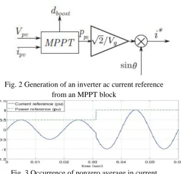
is very sensitive to the presence of dc offset in the inverter terminal voltage. The dc offset can enter from a number of factors such as varying power reference given by a fast MPPT block, the offsets in the A/D converter, and the sensors. To understand how a fast MPPT introduces a dc offset, consider Figs. 2 and 3. I
n Fig. 2, d boost is the duty ratio command given to the boost converter switch, Vpv and ipv are the panel voltage and current, respectively, Ppv is the panel output power, Vg is the rms value of the grid voltage, sin θis the in-phase unit vector for the grid voltage, and i∗ is the reference to the current control loop from an MPPT block. As the power reference keeps on changing due to fast MPPT action, the current reference may have a nonzero average value, which is illustrated in Fig. 3 for a step change in power reference which repeats.
Assume that a certain amount of dc exists in the current control loop. This will result in applying a voltage with a dc offset across the L-filter and the transformer primary. The net average current flowing in the filter and the transformer primary loop will be determined by the net resistance present in the loop. This average current will cause a dc shift in the B–H curve of the transformer. This shift would mean an asymmetric nonlinear saturation characteristic which causes the transformer magnetizing current to lose its half-wave symmetry. The result of this is occurrence of even harmonics. The dc in the system can be eliminated by using the PRI controller which is discussed next.
Fig. 2 Generation of an inverter ac current reference from an MPPT block
Fig. 3 Occurrence of nonzero average in current reference due to a fast changing power reference from
B. Fundamental Current Control
1) Introduction to the PRI Controller: Conventional
stationary reference frame control consists of a PR controller to generate the inverter voltage reference. In this paper, a modification to the PR controller is proposed, by adding an integral block, GI as indicated in Fig. 4. The modified control structure is termed as a PRI controller. Here
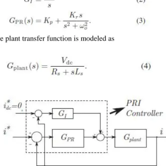
The plant transfer function is modeled as
Fig. 4 Block diagram of the fundamental current control with the PRI controller
This is because the inverter will have a gain of Vdc to the voltage reference generated by the controller and the impedance offered is given by (Rs + sLs ) in s-domain. Rs and Ls are the net resistance and inductance referred to the primary side of the transformer, respectively. Ls include the filter inductance and the leakage inductance of the transformer. Rs are the net series resistance due to the filter inductor and the transformer.
The PRI controller is proposed to ensure that the output current of the system does not contain any dc offset. The PRI controller introduces a zero at s = 0in the closed-loop transfer function. Hence, the output current will not contain any steady-state dc offset. This is necessary in the topology considered because the presence of a dc offset would result in a flow of even harmonics as explained in Section II-A. The following section explains the design of PR controller parameters and proposes a systematic method of selecting and tuning the gain of the integral block in the PRI controller.
2) Design of PRI Controller Parameters: The fundamental current corresponds to the power injected into the grid. The control objective is to achieve UPF operation of the inverter. The main control block diagram is shown in Fig. 4. First, a PR controller is designed for the system assuming that the integral block is absent, i.e., KI = 0. Design of a PR controller is done by considering a PI controller in place of the PR controller. The PI parameters are chosen based on the plant transfer function and the required current controller bandwidth. The PI controller parameters are then plugged in for the PR controller parameters.
With the PI controller as the compensator block in Fig. 4 and without integral block, the forward transfer function will be
The pole in (6) is canceled with the zero given by the PI controller. Then, the following relations are obtained:
If ωbw is the required bandwidth, then Kp1 can be chosen to be
Now, if the PI controller in (5) is written as
Then, Ki1 is given as
For the complete system with an integral block, i.e., the PRI controller, the PR parameters will be same as in (12) and (13). The following procedure is used to select the value of KI in (2). The integral portion is used to ensure that there will not be any steady-state dc in the system. Hence, the overall dynamic performance of the complete system should be similar to that with the PR controller except at the low-frequency region and dc. The closed-loop transfer function for Fig. 4 is given as
Without the integral block, the closed-loop transfer function would be
Let (4) be modified as,
Where M = Vdc/Rs and T is as defined in (7).
The numerators in both (14) and (15) are the same. Thus, the difference in their response is only due to the denominator terms in both. The denominator in (14) can be obtained as
Similarly, the denominator in (15) is given by
The numerators in (17) and (18) are the characteristic polynomials of the closed-loop transfer functions given in (14) and (15), respectively.
Let the numerator polynomial in (17) be written as
Where p corresponds to a real pole. Equating (19) with the numerator in (17), the following relations can be obtained:
If p is such that it is very close to the origin and the remaining three poles in (14) are as close as possible to the poles of (15), then the response in case of the PRI controller and the PR controller will be very similar except for dc and low frequency range. Thus, the remaining third-order polynomial in (19) should have the coefficients very close to the coefficients of the numerator in (18). In that case, using (20), the following conditions can be derived:
can be used to tune the value of KI further, after the design from (21) to (23).
Fig. 5 Comparison of a Bode plot of the closed-loop transfer function with the PRI and PR controllers
Fig. 6 Step response of closed-loop transfer function Gc l,PRI for different values of KI
III. SIMULATION RESULTS
Fig 7 simulation diagram of proposed three phase system
Fig 8 DC link voltage
Fig 9 DC link voltage and reference voltage, modulation index
Fig 10 inverter output voltage
Fig 12 grid side three phase load voltage
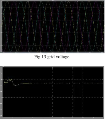
Fig 13 grid voltage
Fig 14 grid side active power
Fig 15 PV panel outputs: power, voltage, duty cycle and irradiance
CONCLUSION
A novel solution is proposed to attenuate all the dominant lower order harmonics in the system. The proposed method uses an LMS adaptive filter to estimate
a particular harmonic in the grid current that needs to be attenuated. The estimated current is converted into an equivalent voltage reference using a proportional controller and added to the inverter voltage reference. Modification to the inverter current control for a grid connected single-phase photovoltaic inverter has been proposed in this paper, for ensuring high quality of the current injected into the grid. For the power circuit topology considered, the dominant causes for lower order harmonic injection are identified as the distorted transformer magnetizing current and the dead time of the inverter. It is also shown that the presence of dc offset in control loop results in even harmonics in the injected current for this topology due to the dc biasing of the transformer. The design of the gain of a proportional controller to have an adequate harmonic compensation has been explained. To avoid dc biasing of the transformer, a novel PRI controller has been proposed and its design has been presented.
The interaction between the PRI controller and the adaptive compensation scheme has been studied. It is shown that there is minimal interaction between the fundamental current controller and the methods responsible for dc offset compensation and adaptive harmonic compensation. The PRI controller and the adaptive compensation scheme together improve the quality of the current injected into the grid. The transient response of the whole system is studied by considering the startup transient and the overall performance is found to agree with the theoretical analysis. It may be noted here that these methods can be used for other applications that use a line interconnection transformer wherein the lower order harmonics have considerable magnitude and need to be attenuated.
REFERENCES
[1] S. B. Kjaer, J. K. Pedersen, and F. Blaabjerg, “A review of single-phase grid-connected inverters for photovoltaic modules,”IEEE Trans. Ind. Appl., vol. 41, no. 5, pp. 1292–1306, Sep./Oct. 2005.
[2] S.-G. Jeung and M.-H. Park, “The analysis and compensation of deadtime effects in PWM inverters,” IEEE Trans. Ind. Electron., vol. 38, no. 2, pp. 108–114, Apr. 1991.
[3] J.-W. Choi and S.-K. Sul, “A new compensation strategy reducing voltage/ current distortion in PWM VSI systems operating with low output voltages,”IEEE Trans. Ind. Appl., vol. 31, no. 5, pp. 1001–1008, Sep./Oct. 1995.
drives,”IEEE Trans. Power Electron., vol. 14, no. 4, pp. 683–689, Jul. 1999.
[5] A. C. Oliveira, C. B. Jacobina, and A. M. N. Lima, “Improved dead-time compensation for sinusoidal PWM inverters operating at high switching frequencies,”IEEE Trans. Ind. Electron., vol. 54, no. 4, pp. 2295–2304, Aug. 2007.
[6] L. Chen and F. Z. Peng,“Dead-time elimination for voltage source inverters,”IEEE Trans. Power Electron., vol. 23, no. 2, pp. 574–580, Mar. 2008.
[7] IEEE Recommended Practices and Requirements for Harmonic Control in Electrical Power Systems, IEEE Standard 519-1992, 1992.
[8] IEEE Standard for Interconnecting Distributed Resources With the Electric Power System, IEEE Standard 1547-2003, 2003.
[9] T. Esram and P. L. Chapman, “Comparison of photovoltaic array maximum power point tracking techniques,”IEEE Trans. Energy Convers., vol. 22, no. 2, pp. 439–449, Jun. 2007.
[10] R. Kadri, J.-P. Gaubert, and G. Champenois, “An improved maximum power point tracking for photovoltaic grid-connected inverter based on voltage-oriented control,” IEEE Trans. Ind. Electron., vol. 58, no. 1, pp. 66–75, Jan. 2011.
[11] T. Kitano, M. Matsui, and D. Xu, “Power sensorless MPPT control scheme utilizing power balance at DC link—System design to ensure stability and response,” in Proc. 27th Annu. Conf. IEEE Ind. Electron. Soc., 2001, vol. 2, pp. 1309–1314.
[12] Y. Chen and K. M. Smedley, “A cost-effective single-stage inverter with maximum power point tracking,”IEEE Trans. Power Electron., vol. 19, no. 5, pp. 1289–1294, Jun. 2004.
[13] Q. Mei, M. Shan, L. Liu, and J. M. Guerrero, “A novel improved variable step-size incremental-resistance MPPT method for PV systems,” IEEE Trans. Ind. Electron., vol. 58, no. 6, pp. 2427–2434, Jun. 2011. [14] A. K. Abdelsalam, A. M. Massoud, S. Ahmed, and P. N. Enjeti, “High-performance adaptive perturb and observe MPPT technique for photovoltaic-based microgrids,”IEEE Trans. Power Electron., vol. 26, no. 4, pp. 1010–1021, Apr. 2011.
[15] P. Mattavelli, “A closed-loop selective harmonic compensation for active filters,”IEEE Trans. Ind. Appl., vol. 37, no. 1, pp. 81–89, Jan./Feb. 2001.
[16] X. Yuan, W. Merk, H. Stemmler, and J. Allmeling, “Stationary-frame generalized integrators for current control of active power filters with zero steady-state error for current harmonics of concern under unbalanced
and distorted operating conditions,” IEEE Trans. Ind. Appl., vol. 38, no. 2, pp. 523–532, Mar./Apr. 2002. [17] J. Allmeling, “A control structure for fast harmonics compensation in active filters,” IEEE Trans. Power Electron., vol. 19, no. 2, pp. 508–514, Mar. 2004. [18] C. Lascu, L. Asiminoaei, I. Boldea, and F. Blaabjerg, “High performance current controller for selective harmonic compensation in active power filters,”IEEE Trans. Power Electron., vol. 22, no. 5, pp. 1826–1835, Sep. 2007.
[19] D. De and V. Ramanarayanan, “A proportional + multiresonant controller for three-phase four-wire high-frequency link inverter,”IEEE Trans. Power Electron., vol. 25, no. 4, pp. 899–906, Apr. 2010.
[20] R. C´ardenas, C. Juri, R. Pen˜na, P.Wheeler, and J. Clare, “The application of resonant controllers to four-leg matrix converters feeding unbalanced or nonlinear loads,”IEEE Trans. Power Electron., vol. 27, no. 3, pp. 1120–1128, Mar. 2012.
[21] A. G. Yepes, F. D. Freijedo, O´ . Lo´pez, and J. Doval-Gandoy, “Highperformance digital resonant controllers implemented with two integrators,” IEEE Trans. Power Electron., vol. 26, no. 2, pp. 563–576, Feb. 2011.
[22] A. G. Yepes, F. D. Freijedo, J. Doval-Gandoy, O. Lopez, J. Malvar, and P. Fernandez-Comesa˜na, “Effects of discretization methods on the performance of resonant controllers,” IEEE Trans. Power Electron., vol. 25, no. 7, pp. 1692–1712, Jul. 2010.
[23] P. Mattavelli and F. P.Marafao, “Repetitive-based control for selective harmonic compensation in active power filters,”IEEE Trans. Ind. Electron., vol. 51, no. 5, pp. 1018–1024, Oct. 2004.
[24] R. Costa-Costello, R. Grino, and E. Fossas, “Odd-harmonic digital repetitive control of a single-phase current active filter,”IEEE Trans. Power Electron., vol. 19, no. 4, pp. 1060–1068, Jul. 2004.
[25] S. Jiang, D. Cao, Y. Li, J. Liu, and F. Z. Peng, “Low-THD, fast-transient, and cost-effective synchronous-frame repetitive controller for three-phase UPS inverters,” IEEE Trans. Power Electron., vol. 27, no. 6, pp. 2994–3005, Jun. 2012.
[26] J. M. Olm, G. A. Ramos, and R. Costa-Costel´o, “Stability analysis of digital repetitive control systems under time-varying sampling period,” IET Control Theor. Appl., vol. 5, no. 1, pp. 29–37, Jan. 2011.
[28] B. Singh and J. Solanki, “An implementation of an adaptive control algorithm for a three-phase shunt active filter,” IEEE Trans. Ind. Electron., vol. 56, no. 8, pp. 2811–2820, Aug. 2009.
[29] L. Qian, D. A. Cartes, and H. Li, “An improved adaptive detectionmethod for power quality improvement,” IEEE Trans. Ind. Appl., vol. 44, no. 2, pp. 525–533, Mar./Apr. 2008.
[30] S.-Y. Kim and S.-Y. Park, “Compensation of dead-time effects based on adaptive harmonic filtering in the vector-controlled AC motor drives,” IEEE Trans. Ind. Electron., vol. 54, no. 3, pp. 1768–1777, Jun. 2007. [31] V. Blasko, “A novel method for selective harmonic elimination in power electronic equipment,”IEEE Trans. Power Electron., vol. 22, no. 1, pp. 223–228, Jan. 2007. [32] A. E. Fitzgerald, C. Kingsley Jr, and S. D. Umans, Electric Machinery, 6th ed. New York: McGraw-Hill, 2003.